LSI AcceleRAID 352 Quick Installation Guide
- Taper
- Quick Installation Guide

AcceleRAID 352
Quick Installation Guide
DB11-000027-00 First Edition
08P5516

Electromagnetic Compatibility Notices
This device complies with Part 15 of the FCC Rules. Operation is subject to
the following two conditions:
1. This device may not cause harmful interference, and
2. This device must accept any interference received, including interference
that may cause undesired operation.
This equipment has been tested and found to comply with the limits for a
Class B digital device, pursuant to part 15 of the FCC Rules. These limits are
designed to provide reasonable protection against harmful interference in a
residential installation. This equipment generates, uses, and can radiate radio
frequency energy and, if not installed and used in accordance with the
instructions, may cause harmful interference to radio communications.
However, there is no guarantee that interference will not occur in a particular
installation. If this equipment does cause harmful interference to radio or
television reception, which can be determined by turning the equipment off
and on, the user is encouraged to try to correct the interference by one or
more of the following measures:
•Reorient or relocate the receiving antenna.
•Increase the separation between the equipment and the receiver.
•Connect the equipment into an outlet on a circuit different from that to
which the receiver is connected.
•Consult the dealer or an experienced radio/TV technician for help.
Shielded cables for SCSI connection external to the cabinet are used in the
compliance testing of this Product. LSI Logic is not responsible for any radio
or television interference caused by unauthorized modification of this
equipment or the substitution or attachment of connecting cables and
equipment other than those specified by LSI Logic. The correction of
interferences caused by such unauthorized modification, substitution, or
attachment will be the responsibility of the user.
The LSI Logic Mylex AcceleRAID 352 is tested to comply with FCC
standards for home or office use.
This Class B digital apparatus meets all requirements of the Canadian

Interference-Causing Equipment Regulations.
Cet appareil numérique de la classe B respecte toutes les exigences du
Règlement sur le matériel brouilleur du Canada.
This is a Class B product based on the standard of the Voluntary Control
Council for Interference from Information Technology Equipment (VCCI).
If this is used near a radio or television receiver in a domestic environment, it
may cause radio interference. Install and use the equipment according to the
instruction manual.
LSI Logic Corporation
North American Headquarters
Milpitas, CA
408.433.8000

Declaration of Conformity
Per FCC Part 2, Section 2.1077(a)
Manufacturer’s Name: LSI Logic Corporation
Manufacturer’s Address:
North American Headquarters
Milpitas, CA
USA
Declares that the product:
Product Name: High Performance RAID Controller
Model Number(s): AcceleRAID 352
Year of Manufacture: 2000
Conforms to the following Product Specification(s):
FCC: CFR 47 Part 15, Subpart B, Section 15.107(e)
and Section 15.109(g) Class B Digital Device
tested per ANSI C63.4–1992 procedures
Supplementary Information:
This device complies with part 15 of the FCC Rules. Operation is subject to
the following two conditions: (1) This device may not cause harmful
interference, and (2) this device must accept any interference received,
including interference that may cause undesired operation.

Declaration of Conformity
Per 89\336\EEC
Responsible Party
Name:
LSI Logic Corporation
Address:
North American Headquarters
Milpitas, CA
U.S.A.
hereby declares that the product
Trade Name: High Performance Caching RAID Controller
Model Number(s):AcceleRAID 352 Fab. 550157-01 Rev. A
conforms to the following specifications
Standards: EN 50081-1:1992, Emissions
EN 55022 Class B (Radiated), Class B (Conducted)
EN 50082-1:1992, Immunity
EN 61000-4-2:1995 Electrostatic Discharge
EN 61000-4-3:1996 Radiated Susceptibility
EN 61000-4-4:1995 Electrical Fast Transients/Burst

Community of Europe
CE mark is rated for the AceleRAID 352 as follows:
CISPR 22 Radiated Emission
EN55022, Generic immunity standard for the following:
IEC 801-2 ESD, IEC 801-3 Radiated, and IEC 801-4 EFT/Burst
Warning!
This is a Class B product. In a residential environment this product may
cause radio interference, in which case the user may be required to take
adequate measures.
Achtung!
Dieses ist ein Gerät der Funkstörgrenzwertklasse B. In Wohnbereichen
können bei Betrieb dieses Gerätes Rundfunkstörungen aufreten, in welchen
Fällen der Benutzer für entsprechende Gegenmaßnahmen verantwortlich ist.
Avertissement!
Cet appareil est un appareil de Classe B. Dans un environnement résidentiel
cet appareil peut provoquer des brouillages radioélectriques. Dans ce cas, il
peut être demandé à l’utilisateur de prendre des mésures appropriées.

Underwriters Laboratories Statement and Warning

Proprietary Rights Notice
This document contains proprietary information of LSI Logic
Corporation. The information contained herein is not to be used by
or disclosed to third parties without the express written permission
of an officer of LSI Logic Corporation. Any product(s) described
herein is/are a licensed product of LSI Logic Corporation.
Document Description
Document DB11-000027-00 First Edition. November 2002
This document describes the LSI Logic Corporation’s Mylex
AcceleRAID 352 product for Software Kit 5.20 and will remain the
official reference source for all revisions/releases of this product
until rescinded by an update.
Disclaimer
It is the policy of LSI Logic to improve products as new technology,
components, software, and firmware become available. LSI Logic
Corporation reserves the right to make changes to any products
herein at any time without notice. All features, functions, and
operations described herein may not be marketed by LSI Logic in
all parts of the world. In some instances, photographs and figures
are of equipment prototypes. Therefore, before using this
document, consult your LSI Logic representative for information
that is applicable and current. LSI LOGIC DOES NOT ASSUME
ANY RESPONSIBILITY OR LIABILITY FOR THE USE OF
ANY PRODUCT(S) DESCRIBED HEREIN EXCEPT AS
EXPRESSLY AGREED TO IN WRITING BY LSI LOGIC.
License Restriction
The purchase or use of an LSI Logic product does not convey a
license under any patent, copyright, trademark, or other intellectual
property right of LSI Logic or third parties.
Copyright Notice
Copyright © 2001, 2002. LSI Logic Corporation. All rights
reserved.

Trademark Acknowledgments
LSI Logic, the LSI Logic logo, MORE, Mylex, and SANmapping
are trademarks or registered trademarks of LSI Logic Corporation.
All other brand and product names may be trademarks of their
respective companies.


Manual No. DB11-00027-00 1
Contents
Hardware Installation
Introduction ........................................................................................1-1
Performing an Installation ..................................................................1-1
PCI Hot Plug ..............................................................................1-1
Connectors, Jumpers, and LEDs ...............................................1-1
Installing the AcceleRAID 352 into the System Board ...............1-5
What to Do Next ................................................................................1-7
SOFTWARE LICENSE AND WARRANTY POLICY

2 AcceleRAID 352 Installation Guide

Manual No. DB11-00027-00 1
Hardware Installation
Introduction
The AcceleRAID 352 is a versatile PCI to a dual channel Ultra 160 SCSI,
Low Voltage Differential (LVD) RAID controller. There are many possible
hardware configurations. This quick installation guide assumes that the user
is familiar with controller, disk drive, and RAID terminology.
Performing an Installation
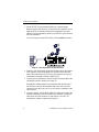
WARNING
To avoid electrical shock, do not attempt to
perform this hardware installation with power on.
Disconnect the system from the electrical wall
outlet.
PCI Hot Plug
Please refer to Appendix D in the AcceleRAID 352 PCI to Ultra 160 SCSI
RAID Controller Installation Guide for instructions on how to use the PCI
Hot Plug feature.
Connectors, Jumpers, and LEDs
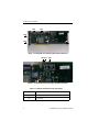
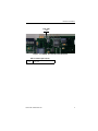
There are two Ultra 160 SCSI external channels and two Ultra 160 SCSI
internal channels supported on the controller. The SCSI connector locations
are shown in Figure 1.
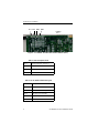
All the jumpers should normally be set to their default settings. See Table 1
for default jumper settings. Jumper locations are shown in Figure 2.
The front side of the controller has one LED that is described in Figure 3 and
in Table 2. The back side of the controller has four LEDs that are mode
indicators while the controller is running. These LEDs indicate single-ended
mode and LVD mode and are described in Figure 4 and in Table 3.

Performing an Installation
2 AcceleRAID 352 Quick Installation Guide
Figure 1. AcceleRAID 352 Controller with Channel Connectors
Figure 2. AcceleRAID 352 Default Jumper Identification (front)
Table 1. AcceleRAID 352 Default Jumper Descriptions
JP1 Blank ROM mode; do not use
JP2 Maintenance mode; do not use
JP3 6-pin header
CH0
CH1
CH0 CH1
JP1 JP2 JP3
JP1 JP2 JP3

Hardware Installation
Manual No. DB11-00027-00 3
Figure 3. AcceleRAID 352 Controller with LED (front)
Table 2. LED Description (front)
U1 FAIL LED
FAIL LED
U1

Performing an Installation
4 AcceleRAID 352 Quick Installation Guide
Figure 4. AcceleRAID 352 with LEDs and PIN Numbers (back)
Table 3. LED Descriptions (back)
SE 1 Single-ended LED, Channel 1
SE 0 Single-ended LED, Channel 0
LVD 0 LVD LED, Channel 0
LVD 1 LVD LED, Channel 1
Table 4. Six-Pin Header Identification (JP3)
Pin 1 3.3V power
Pin 2 Channel 0 SCSI activity
Pin 3 Channel 1 SCSI activity
Pin 4 Not used, not connected
Pin 5 Cache Dirty and SCSI activity
Pin 6 Ground pin
SE 1 SE 0 LVD 0 LVD 1
PIN Nos.
654321

Hardware Installation
Manual No. DB11-00027-00 5
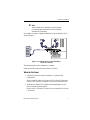
Installing the AcceleRAID 352 into the System Board
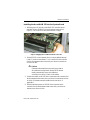
1. With the power off, plug the AcceleRAID 352 controller into an
available 32-bit or 64-bit PCI slot on the system board (refer to
Figure 5). The 32-bit slot is short, the 64-bit slot is longer.
Figure 5. Plugging the AcceleRAID 352 into a PCI Slot
2. Set the SCSI ID on each internal drive to a unique address between
0 and 15, but do not use address 7, as it is reserved for the controller.
See the documentation that comes with your drives for instructions
on how to do this.
Caution
If internal and external drives are used, be sure that no
drive addresses are duplicated. External SCSI cabinets
usually automatically assign drive addresses
according to the drives’ location in the cabinet.
3. Disable termination on all SCSI drives connected to the controller. See
the documentation that comes with your drives for instructions on how
to do this. (Termination must be enabled on the last device, if
applicable.)
4. Enable termination power on all SCSI drives connected to the
controller. See the documentation that comes with your drives for
instructions on how to do this.

Performing an Installation
6 AcceleRAID 352 Quick Installation Guide
5. Set the SCSI ID for each external disk drive to a unique address
between 0 and 15, but do not use 7 (reserved for the controller). Do not
duplicate SCSI IDs used by internal drives designated for the same
channel. For more information on how to set SCSI IDs, refer to the disk
drive documentation.
If you are using an external SCSI cabinet, see the Caution note above.
Figure 6. Connecting Internal and External Drives
6. Connect a wide, high-density, 68-pin SCSI ribbon cable to the internal
SCSI connector on the AcceleRAID 352 controller and connect the
other cable connectors to any SCSI devices as required (see Figure 6).
Termination is automatic on the AcceleRAID 352.
7. Connect an active terminator to the end of the SCSI ribbon cable at the
end farthest from the controller (see Figure 6).
External drive cabinets usually have termination built into the end of
the SCSI bus. Check the documentation that comes with your drive
cabinet to be sure this is the case. If not, use an active terminator at the
end of the bus.
8. Connect a cable(s), with the 68 pin VHDCI, to either one or both of the
external connector(s) on the AcceleRAID 352 controller. Connect the
other end of the cable connector, to other devices or to a SAF-TE
external drive cabinet, as required (see Figure 6).

Hardware Installation
Manual No. DB11-00027-00 7
☛Note
The AcceleRAID 352 terminator is ON by default.
It is automatically terminated and will be disabled
automatically if necessary.
An example of a typical, completed installation of the AcceleRAID 352 is
shown in Figure 7.
Figure 7. AcceleRAID 352 in a Typical Installation
and SCSI Connectors
The hardware portion of the installation is complete.
Please see the following section titled “What to Do Next”.
What to Do Next
1. Use RAID EzAssist to create an automatic or a custom RAID
configuration.
Refer to the RAID EzAssist Configuration Utility Quick Configuration
Guide or RAID EzAssist Configuration Utility User Reference Guide.
2. Install the AcceleRAID 352 controller drivers appropriate for your
server’s network operating system.
Refer to the PCI Disk Array Controller Drivers Installation Guide and
User Manual.
System Board
T
T

What to Do Next
8 AcceleRAID 352 Quick Installation Guide
La page est en cours de chargement...
La page est en cours de chargement...
La page est en cours de chargement...
La page est en cours de chargement...
-
 1
1
-
 2
2
-
 3
3
-
 4
4
-
 5
5
-
 6
6
-
 7
7
-
 8
8
-
 9
9
-
 10
10
-
 11
11
-
 12
12
-
 13
13
-
 14
14
-
 15
15
-
 16
16
-
 17
17
-
 18
18
-
 19
19
-
 20
20
-
 21
21
-
 22
22
-
 23
23
-
 24
24


LSI AcceleRAID 352 Quick Installation Guide
- Taper
- Quick Installation Guide
dans d''autres langues
- English: LSI AcceleRAID 352