
I
I
stallatio
structio
S
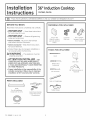
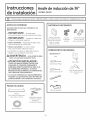
36" Induction Cooktop
PHP960, ZHU36
[] If you have questions, call 800.GE.CARESor visit our website at GEApplionces.com
BEFORE YOU BEGIN
Read these instructions completely and carefully.
, IMPORTANT - Savetheseinstructions
for local inspector's use.
, IMPORTANT - Observeollgoverning
codes and ordinances.
, Note to Installer- Be sure to leave these
instructions with the Consumer.
, Note to Consumer - Keep these instructions
for future reference.
, Product failure due to improper installation is
not covered under the Warranty.
A WARNING - This appliance must be
properly grounded.
. ATTENTION INSTALLER - ALL
COOKTOPS MUST BE HARD WIRED IDIRECT
WIRED} INTO AN APPROVED JUNCTION BOX.
A "PLUG AND RECEPTACLE" IS NOT PERMITTED
ON THESE PRODUCTS.
, Proper installation is the responsibility of the
installer and product failure due to improper
installation is NOT covered under warranty.
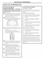
PARTS INCLUDED
Baffle
(For all installations
except over an oven.)
2 Hold-Down Brackets
6 Hex-Head Screws
2 Thumbscrews
Foam Tape
MATERIALS YOU WILL NEED
Junction Box Large Size
(Sizedfor conduit Wire Nuts
per local electrical
codes.)
90° or Straight
Squeeze Connector
for !" Conduit
TOOLS YOU WILL NEED
Pencil
Phillips Head
Screwdriver
1/4" Nut Driver
Saber Saw
1/8" Drill Bit & Electric or
Hand Drill
Ruler or Straightedge
Safety Glasses
31-i0668-i (06-12 GE) 1

Installation Instructions
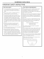
IMPORTANT SAFETY INSTRUCTIONS
w
FOR YOUR SAFETY
. For Personal Safety, remove house fuse or open
circuit breaker before beginning installation.
Failure to do so could result in serious injury or
death.
. Be sure your cooktop is installed properly by a
qualified installer or service technician.
. To eliminate the risk of burns or fire due to
reaching over heated surface elements, cabinet
storage located above the surface units should
be avoided. If cabinet storage space is to be
provided, the risk can be reduced by installing a
range hood that projects horizontally a minimum
of 5" beyond the bottom of the cabinets. Cabinet
installation above the cooktop may be no deeper
than 13".
. Make sure the cabinets and wall coverings
around the cooktop can withstand the
temperatures (up to 200°F) generated by the
cooktop.
. The cooktop should be easy to reach and lighted
with natural light during the day.
. Always disconnect the electrical service to
the cooktop before repairing or servicing the
cooktop. This can be done by disconnecting the
fuse or circuit breaker. Failure to do this could
result in a dangerous or fatal shock. Know where
your main disconnect switch is located. If you do
not know, have your electrician show you.
ELECTRICAL REQUIREMENTS
This appliance must be supplied with the proper
voltage and frequency, and connected to an
individual, properly grounded branch circuit,
protected by a circuit breaker or a time delay fuse
as noted on name plate.
We recommend you have the electrical wiring and
hookup of your cooktop connected by a qualified
electrician. After installation, have the electrician
show you where your main cooktop disconnect is
located.
Wiring must conform to National Electrical Code
and all local electrical codes. You can get a copy
of the National Electrical Code, ANSI/NFPA No.
70-Latest Edition, by writing:
National Fire Protection Association
Batterymarch Park
Quincy, MA 02269
In Canada, wiring must conform to Canadian
Electrical Code (CEC).
The cooktop conduit wiring is approved for copper
wire connection only, and if you have aluminum
house wiring, you must use special UL approved
connectors for joining copper to aluminum. In
Canada, you must use special CSA approved
connectors for joining copper to aluminum.
You must use a two-wire, three conductor 208/240
VAC, 60 Hertz electrical system. A white (neutral)
wire is not needed for this unit.
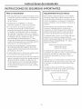
Refer to the name plate on your cooktop for the
KW rating for your cooktop.
These cooktops require SOamp service.
T
Name plate location

Installation Instructions
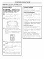
PRE-INSTALLATION CHECKLIST
BEFORE YOU BEGIN
A WARN ING - Theelectricalpowerto
the cooktop supply line must be shut off while
connections are being made. Failure to do so
could result in serious injury or death.
D When preparing cooktop opening, make sure
the inside of the cabinet and the cooktop do
not interfere with each other. (See section on
preparing the opening.)
Remove packaging materials and literature
package from the cooktop before beginning
installation.
E]
Remove Installation Instructions from the
literature pack and read them carefully before
you begin.
Be sure to place all literature, Owner's Manual,
Installations, etc. in a safe place for future
reference.
Hake sure you have all the tools and materials
you need before starting the installation of the
cooktop.
Your home must provide the adequate
electrical service needed to safely and
properly use your cooktop. (Refer to section on
electrical requirements.)
When installing your cooktop in your home,
make sure all local codes and ordinances are
followed exactly as stated.
Hake sure the wall coverings, countertop and
cabinets around the cooktop can withstand
heat (up to 200°F) generated by the cooktop.
ADVANCE PLANNING
Combination Installations
These cooktops may be installed in combination
with an approved downdraft vent or a single oven.
Cooktop and a Downdraft Vent
The countertop must have a deep flat surface
to accommodate the combined installation of
the cooktop and vent.
Consideration must be given to the separate
electrical supply locations.
Allow 12" clearance between the inlet air ports
on the cooktop bottom toward the rear to any
obstruction.
- Both the cooktop and the vent must be installed
according to each specific product installation
instruction.
Cooktop with a Single Oven
- Consideration must be given to the separate
electrical requirements and locations.
- Both the cooktop and the oven must be installed
according to each specific product installation
instruction.
Installation Above Cabinet Drawers
Allow 12" clearance to combustibles below the
cooktop. A drawer directly below the cooktop
cannot be used to store items such as towels or
paper products. Use a false drawer front to obtain
clearance if necessary.

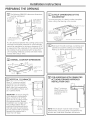
PREPARING THE
Installation
OPENING
Instructions
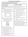
| The following MINIMUM clearance dimensions
must be maintained.
13" IVlAXDepth _._ _J__l _
of uprotected 2" IVllN.Clearance
overhead from cutout to
cabinets side wall on the
right of the unit
Clearance from lS" IV]IN,Height
countertop to countertop to
unprotected nearest cabinet on
overhead either side of unit
surface
2" MIN. Clearance from
cutout to side wall on the
left of the unit
If a 30" clearance between the cooking surface and
overhead combustible materials or metal cabinets
cannot be maintained, a minimum clearance of 24"
is required and the underside of the cabinets above
the cooktop must be protected with not less than
1/4" insulating millboard covered with sheet metal
not less than 0.0122" thick.
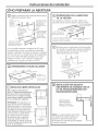
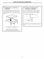
r_ OVERALL COOKTOP DIMENSIONS
18-7/8" ,_,.,_ _
336/8"
4-5/8" at front
baffle
3-1/4" at rear air
intake
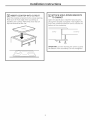
r_ VERTICAL CLEARANCES
Allow 12" minimum vertical -_
clearance from the cooktop 14-1/_,
!
bottom (or 14-1/4" minimum
depth from the countertop) to
any combustible surfaces, such
as a cabinet drawer.
IMPORTANT: To ensure long life
of the electronic components,
allow a minimum of 12" free
space for air circulation below
the cooktop bottom. (Except
installation over a single oven.)
The cooktop bottom has air
intake ports and exhaust ports
that help cool the components.
Do not install a shelf or partition
beneath the cooktop that is
more than 18" deep.
DRAWER 1
12"
18" Hax.
Deep Shelf
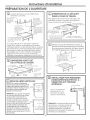
CUTOUT DIMENSIONS OF THE
COUNTERTOP
To insure accuracy, it is best to make a template
when cutting the opening in the counter.
!
1-3/4" IVlin.Between
cutout and the wall
behind the cooktop
2-1/2" Min. from
front edge of cutout
and front edge of
eountertop
19-1/8" depth of cutout
Use a 36" or wider cabinet base.
r_ Make sure the wall coverings, countertop and
cabinets around the cooktop can withstand
heat (up to 200°F) generated by the cooktop.
Wall coverings,
cabinets and
countertop must
withstand heat
up to 200°F.
J
r6] FOR AMERICANS WITH DISABILITIES
ACT (ADA} FORWARD APPROACH
INSTALLATION ON LY:
Allow 5" minimum
depth between the
countertop and an
enclosure.
__
NOTE:The enclosure must be made of wood
material. Also, an access panel is required for the
junction box, hold-down brackets, and service.

Installation Instructions
INSTALLING OPTIONS
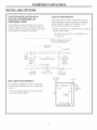
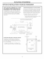
COOKTOP INSTALLATION WITH
A GE OR GE MONOGRAM 30"
DOWNDRAFT VENT
The installation of the downdraft vent with this
cooktop requires careful consideration. Both the
cooktop and the vent must be installed according
to each specific installation instruction.
COOKTOP REQUIREMENTS
The countertop must have a deep flat surface to
accommodate the cooktop and vent. Countertops
with a rolled front edge and backsplash will not
provide the flat surface area required.
, Review the illustration to determine the countertop
surface requirements.
- All cutout clearances for this installation must
be observed.
1-3/4"Min. Cool<topCutoutto Rear
VerticalCombustibleSurface
f 2-3/4"
21-3/4"
Cutout
Depth 19-1/8"
Cooktop
Cutout
Depth
FrontEdge
of Countertop
36-1/8"(SS)
36"(B,W)
34"
Cool<topandVentCutout
" 1/4"Overlap
.._1/8" Gap
23"(SS)
1-1/32"at Center
2-1/2"Min.
Clearanceto Cutout
22-7/8"(B,W)
Total Flat
Surface
Required
2" Min. Cutout
to SideWalls
BASE CABINET REQUIREMENTS
The combined installation will fit in a standard
24" deep bose cabinet. Use a 36" or wider bose
cabinet.
- The vent housing, blower and ductwork will
occupy the bose cabinet.
2-1/2" to
Cutout 1-7/8"
/
22-3/4" Inside
.....22"to Support Rail.......................
I
3/4"
Thick
Support
Rail

Installation Instructions
INSTALLING OPTIONS
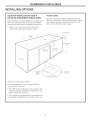
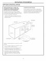
COOKTOP INSTALLATION OVER A
GE OR GE MONOGRAM SINGLE OVEN
These cooktops may be installed over a single oven.
Both the cooktop and the oven must be installed
according to each specific installation instruction.
- Allow 4" Hin. clearance from the top of the
countertop to the top of the oven cutout.
POWER SUPPLY
The oven requires a separate, properly grounded
20 Amp, ]-wire 208 or 240 volt, 60 Hz power supply.
The cooktop requires a separate 50 Amp, ]-wire,
208 or 240 volt, 60 Hz power supply.
23-1/2"min.
Cooktop
33-7/8"
28-l/2"min.
28-5/8"max.
3/4"support
platform
required
1-1/2"cabinettop
36" countertop
4"min. height
27-1/4"min.
27-5/16"max.
Mustmatch
toekickheight
Use a 36" or wider base cabinet.
, For best appearance, the cooktop should be
centered over the oven.
. The baffle on the underside of the cooktop is not
necessary for this combination installation. If the
baffle is attached, remove it.
, This cooktop is only approved to be installed over
the specific models listed on the label of this unit.

Installation Instructions
ELECTRICAL CONNECTIONS
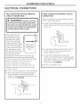
NEW CONSTRUCTION AND BRANCH
CIRCUIT CONNECTION
A WARNING: Improper connection
of aluminum house wiring to copper leads
can result in an electrical hazard or fire. Use
only connectors designed for joining copper
to aluminum and follow the manufacturer's
recommended procedure closely.
When making the wire
connections, use the
entire length of conduit
provided. The conduit
must not be shortened
(unless required by local
codes). The conduit length
is 4 ft. With the cooktop
in place, open the front of
the cabinet door. Insert
the wires from the conduit
through the opening of
the junction box. The
116"
Install junction box
so that it can be
reached through
the front of the
cabinet.
1
conduit strain relief clamp must be securely
attached to the junction box and the flexible
conduit must be securely attached to the clamp.
• When installing in new construction, or
• When installing in a mobile home, or
• When installing in a recreational vehicle, or
• When local codes do not permit grounding
through neutral:
a. Insert conduit through strain relief and tighten.
b. Attach the appliance grounding lead (green
or bare copper)in accordance with local
codes. If the residence grounding conductor is
aluminum, see WARNING.
Strain Relief ___,,
Junction Box Cover
Ground Wire
THREE-CONDUCTOR BRANCH CIRCUIT
CONNECTION
When connecting to a three-conductor branch
circuit, if local codes permit:
a. Connect the cooktop green ground conductor
lead to the branch circuit ground (green) using
a wire nut.
b,
C°
[_ G_round and
Neutral Wires
Junction Box Cover
Connect the cooktop red lead to the branch
circuit red lead in accordance with local
codes, using a wire nut.
Connect the cooktop black lead to the
branch circuit black lead in accordance with
local codes, using a wire nut. If the residence
red, black or white leads are aluminum
conductors, see WARNING.
d. Install Junction Box Cover.

Installation Instructions
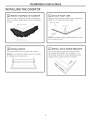
INSTALLING THE COOKTOP
r_ PROTECT SURFACE OF COOKTOP
Place a towel or tablecloth onto the countertop.
Lay the cooktop upside down onto the protected
surface.
Bottom of Cooktop
Cloth under Cooktop
ATTACH FOAM TAPE
Apply the foam tape around the outer edge of the
glass. Do not overlap the foam tape.
Bottom of Cooktop
" - -1 Foam Tape --................."
'" -...... i--"""'" @
._--_i_....
Cooktop -"- ........
NOTE: On stainless steel models, apply foam tape
on the sides and rear.
[_] INSTALL BAFFLE
Secure the baffle to the cooktop with screws.
NOTE: Do not install the baffle when the cooktop
is installed over a single oven.
? ?
[_ INSTALL HOLD-DOWN BRACKETS
Start one screw through the bracket and into
the cooktop. (Both sides.) Do not tighten. Turn
the bracket inwards to avoid interference when
dropping the cooktop into the countertop.

Installation Instructions
INSERT COOKTOP INTO CUTOUT
Insert the cooktop centered into the cutout opening.
Make sure the front edge of the countertop is
parallel to the cooktop. Hake final check that all
required clearances are met.
[]_] ATTACH HOLD-DOWN BRACKETS
TO CABINET
Open the cabinet door. Install the second screw
through the bracket and tighten. Then tighten the
first screw. Install thumbscrew until it touches the
bottom of the countertop.
oooIL
L I
i
Countertop
IMPORTANT: Turn the thumbscrew until it touches
the bottom of the countertop. Do not overtighten.

Installation Instructions
CHECKLISTS
[]
D
[]
[]
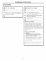
PRE-TEST CHECKLIST
Remove all protective film, if present, and any
stickers.
Check to be sure that all wiring is secure and
not pinched or in contact with moving parts.
Check level of appliance.
Check that the cooktop is properly grounded.
[_ OPERATION CHECKLIST
D
D
D
Remove all items from the top of the cooktop
surface.
Turn on the power to the cooktop.
(Refer to your Owner's Manual.) Verify that all
surface burners operate properly.
Check that the circuit breaker is not tripped
nor the house fuse blown.
Check that conduit is securely connected to
the junction box.
See Owner's Manual for troubleshooting list.
NOTE TO ELECTRICIAN:
The power leads supplied with this appliance are
UL recognized for connections to larger gauge
household wiring. The insulation of these leads
is rated at temperatures much higher than the
temperature rating of household wiring. The current
carrying capacity of a conductor is governed by the
wire gauge and also the temperature rating of the
insulation around
the wire.
NOTE: ALUMINUM WIRING
, WARNING:
IMPROPER CONNECTION OF ALUMINUM
HOUSE WIRING TO THE COPPER LEADS CAN
RESULT IN A SERIOUS PROBLEM.
, Splice copper wires to aluminum wiring using
special connectors designed and UL approved
for joining copper to aluminum and follow
the manufacturer's recommended connector
procedure closely.
NOTE: Wire used, location and enclosure of splices,
etc., must conform to good wiring practice and
local codes.
10

I str cti
d'i stall t"
Tabledecuisson6
induction de 36" ZHUS
AVANT DE COMMENCER
Lisez ottentivement Io totolit6 de ces
instructions.
.IMPORTANT - Conservezces
instructions(_l'usogede l'inspecteurlocal
.IMPORTANT mespectez toutesles
normes etlesr6glementotionsen vigueur
, Remorque a l'instolloteur- Assurez-vousde
Ioisserces instructionsou consommoteur
, Remorque a I'instolloteur - Conservez ces
instructions pour future r#f#rence.
, Les pc]nnes du produit provoqu6es par une
installation incorrecte ne sont pas couvertes par
Ic]gc]rc]ntie.
A AVERTISSEMENT - ceteppereil
doit @tre correctement reccord@ a Ie terre.
oATTENTION INSTALLATEUR
-- TOUTES LES TABLES DE CUISSON DOIVENT
f:TRE RACCORDEES (CABLF!:ES)DIRECTEMENT
A UNE BOITE DE DI_RIVATION AGR##E. UNE
PROCI_DURE <<FICHE ET PRISE DE COURANT >>
N'EST PAS AUTORIS#E SUR CES PRODUITS.
, Une installation correcte est de Io
responsobilit_ de I'instolloteur et les ponnes
provoqu@es par une installation incorrecte NE
sont PAS couvertes par Io gorontie.
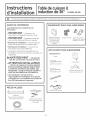
PII_CES INCLUSES
D6flecteur
(pourtoutes lesinstallations
saufau-dessusd'unfour) 2 fixations de mointien
6visa t@te hexogonole
2 vis popillon
L'isolant adh6sif
I_QUIPEMENTSDONT VOUS AUREZ BESOIN
BoTtede d@rivation
(odopt@eaux c6bles
et conforme oux
normes @lectriques
locales)
Grands serre-fils
Connecteur _ sertir
droit ou a 90° pour ur
cable de 2 cm (3/4")
OUTILS DONT VOUS AUREZ BESOIN
Crayon
Tournevis cruciforme
Scie sauteuse
CI#(_douille de 1/4"
R@gle
Perceuse 61ectrique ou (_
main avec foret de 1/8"
Lunettes de protection
11

Instructions d'installation
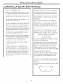
CONSIGNES DE SI CURITI IMPORTANTES
POUR VOTRE Si_CURITI_
. Pour votre s#curit# personnelle, enlevez le fusible
ou coupez le disjoncteur avant de commencer
I'installation. Le non-respect de cette consigne
peut provoquer des blessures graves ou la mort.
. Assurez-vous que la table de cuisson est
correctement install6e par un installateur ou un
technicien de service qualifi#.
. Pour 61iminer le risque de brOlure ou d'incendie
au-dessus des 616ments de surface chauds, il est
pr6f6rable d'#viter I'installation de placards de
rangement au-dessus des unit6s de surface. Si
un espace de rangement dolt 6tre am6nag6, le
risque peut 6tre r6duit en installant une hotte qui
d#passe horizontalement d'un minimum de 12,7
cm (5") au-del6 du bas des placards. L'installation
d'un placard au-dessus de la table de cuisson
peut ne pas d6passer 33 cm (13").
. Assurez-vous que les placards et les rev6tements
muraux autour de la table de cuisson peuvent
supporter les hautes temp6ratures (jusqu'6 93°C
[200°F]) g6n6r6es par la table de cuisson.
. La table de cuisson dolt @trefacilement
accessible et 6clair6e par la lumi6re naturelle
pendant la journ6e.
. D6branchez toujours le circuit 61ectrique de
la table de cuisson avant une r6paration ou
I'entretien de la table de cuisson. Pour ce faire,
d6montez le fusible ou coupez le disjoncteur. Le
non-respect de cette consigne peut provoquer
un choc 61ectrique grave ou mortel. Sachez oO
se trouve le disjoncteur de votre alimentation
61ectrique. Si vous ne le savez pas, demandez 6
votre 61ectricien.
CONDITIONS I_LECTRIQUES REQUISES
Cet appareil doit 6tre aliment6 avec la tension
et la fr6quence correcte, branch6 sur un circuit
d6riv6 individuel, correctement raccord6 6 la
terre, prot6g6 par un coupe-circuit ou un fusible
de temporisation, comme indiqu6 sur la plaque
signal6tique.
Nous vous recommandons de faire r6aliser le
c_blage et le raccordement 61ectrique de votre
table de cuisson par un 61ectricien qualifi6. Apr6s
I'installation, demandez 6 1'61ectricien de vous
montrer oQ se trouve le disjoncteur principal de
votre table de cuisson.
Le c#]blage doit #tre conforme au Code national
61ectrique et aux normes locales. Vous pouvez
obtenir une copie du Code national 61ectrique,
ANSI/NFPA N° 70 - derni6re #dition, en 6crivant 6 :
National Fire Protection Association
Batterymarch Park
Quincy, MA 02269
Au Canada, le cSblage doit se conformer au Code
canadien de 1'61ectricit6 (CCE).
Le c_blage de la table de cuisson est approuv6
uniquement pour un branchement avec des fils
de cuivre, et si le c_blage de votre maison est en
aluminium, vous devrez utiliser un connecteur
sp6cial approuv6 UL pour raccorder les fils de
cuivre 6 ceux d'aluminium. Au Canada, vous devez
utiliser des connecteurs sp6ciaux homologu6s CSA
pourjoindre le cuivre 6 I'aluminium.
Vous devez utiliser un syst6me 61ectrique 6 deux
fils, trois conducteurs 208/240 V CA, 60 Hz. Un
fil blanc (neutre) n'est pas n6cessaire pour cet
appareil.
Consultez la plaque signal6tique de votre table de
cuisson pour connaTtre I'indice KW de votre table
de cuisson.
Ces tables de cuisson n6cessitent un service de 50
amp6res.
Emplacement de la plaque signal6tique
12

Instructions d'installation
CHECK-LIST DE PREPARATION
AVANT DE COMMENCER
A AVERTISSEMENT - L'alimentation
_lectrique de Io table de cuisson doit 6tre couple
pour effectuer les roccordements. Le non-respect
de cette consigne peut provoquer des blessures
graves ou la mort.
[] Lors de Ic]pr6pc]rc]tion de I'ouverture pour Ic]
tc]ble de cuisson, c]ssurez-vous que I'int6rieur
du meuble et Ic]tc]ble de cuisson n'interf6rent
pc]s I'un c]vec I'c]utre. (Voir Ic]section sur Ic]
pr6pc]rc]tion de I'ouverture.)
r_ Enlevez les mc]t6ric]ux d'embc]llc]ge et
I'ensemble de Ic]documentc]tion de Ic]tc]ble de
cuisson c]vc]nt de commencer I'instc]llc]tion.
[]
[]
Sortez les instructions d'instc]llation dujeu de
documents et lisez-les c]ttentivement c]vc]nt de
commencer.
Assurez-vous de conserver toute Ic]
documentation, le manuel d'utilisc]tion, les
instructions d'instc]llc]tion, etc., dc]ns un endroit
sOr pour future r#f6rence.
_AsYI.STA_TIONO_YOUR_EW
Assurez-vous de disposer de tous les outils et
les 6quipements dont vous c]urez besoin c]vc]nt
de commencer I'instc]llc]tion de Ic]tc]ble de
cuisson.
rTI votre domicile dolt proposer le service
61ectrique appropri6 et n6cessc]ire pour une
utilisc]tion correcte et en toute s6curit6 de
votre tc]ble de cuisson. (Voir Ic]section sur les
conditions 61ectriques requises.)
r_ Lors de I'instc]llc]tion de Ic]tc]ble de cuisson 6
votre domicile, c]ssurez-vous que toutes les
r6glementc]tions et les normes Iocc]les sont
scrupuleusement respect6es.
r_ Assurez-vous que les rev6tements murc]u×, le
plc]n de trc]vc]il et les plc]cc]rds c]utour de Ic]
tc]ble de cuisson peuvent supporter Ic]chc]leur
(jusqu'6 93°C [200°F]) g6n6r6e pc]r Ic]tc]ble de
cuisson.
PLAN IFICATI ON AVANCf_E
Installations combin_es
Ces tables de cuisson peuvent 6tre instc]ll6es en
combinc]ison c]vec un extrc]cteur c]gr66 ou un four
simple.
Table de cuisson et extrocteur
Le plan de travail doit disposer d'une surface
plc]te et profonde pour c]ccepter I'instc]llc]tion
combin6e d'une tc]ble de cuisson et d'un
extrc]cteur.
II est n6cessaire de prendre en compte des
emplacements s6par6s pour I'alimentc]tion
61ectrique.
Laissez un espc]ce libre de 30 cm (12") entre les
prises d'c]_rc]tion du fond de Ic]tc]ble de cuisson
et I'c]rri_re du meuble.
- La table de cuisson et I'e×trc]cteur doivent _tre
instc]ll6s conform6ment 6 leurs instructions
d'instc]llc]tion respectives.
Table de cuisson et four simple
II est n_cessaire de prendre en compte des
emplacements et des conditions 61ectriques
requises s_pc]r6es.
Lc] tc]ble de cuisson et le four doivent _tre
instc]ll_s conform_ment 6 leurs instructions
d'instc]llc]tion respectives.
Installation ou-dessus de tiroirs de rongement
Laissez un espc]ce libre de 30 cm (12") pour les
combustibles sous la table de cuisson. Un tiroir
situs directement sous Ic]tc]ble de cuisson ne peut
pc]s _tre utilis6 pour stocker des c]rticles comme
des serviettes ou des produits en pc]pier. Utilisez en
fc]qc]de un fc]u× tiroir pour mc]squer I'espc]ce vide si
n6cessc]ire.
13

Instructions d'instollotion
PREPARATION DE L'OUVERTURE
| L'espace libre dolt avoir AU MINIMUM les
dimensions suivantes.
33 cm (13") 5 cm (2")MIN.
de profondeur d'espace libre
des placards
sur la droite de
sup6rieurs non I'appareil, du bard
prot6g#s de I'ouverture 6 la
pard murale
76 cm (30") IV]IN.
d'espace libre
entre le plan de
travail et la surface
sup@ieure non
prot6g#e
38 cm (15")MIN.de
cSt6s de I'appareil,
du plan de travail
au placard le plus
sproche
5 cm (2") MIN.d'es
sur la gauche de I'appareil,
du bard de I'ouverture 6 la
pard murale
Siun espace libre de 76 cm (50'1entre Iasurface de
cuisson et les mat@iaux combustibles ou les placards
m@taltiquessup@burs ne peut pas @treobtenu, un espace
Iibre minimal de 61 cm (24")sera n@cessaireet le dessous
des placards, au-dessus de la table de cuisson, devront
@treprot@g@savec un carton d'isolation d'une @aisseur
sup@ieure 6 6 mm (1/4")et recouvert d'une feuitle
m@altiqued'une @paisseursup@ieure 60,3 mm (0,0122").
[_] DIMENSIONS HORS TOUT
DE LA TABLE DE CUISSON
........ 53 cm (20-7/8")
(91 YcZ_?_ t_8'', ( _S)SS _J.'_"_ (5-3,3"q"_ (533 cm [2r' ssll aueentre'cm
Table de cuisson _ _ au d6flecteur
-*"__ - 8,3 cm (3-1/4")
85,4 cm
47,9cm _ ].,._ 6 Ioprise d'air
(33-5/8"1
(18-7/8") _ arri@re
r_ ESPACES LIBRES VERTICAU×
RENAROUE:Laissezun d_g0gement
verticalminimum de30 cm (12po)entre 562c-[
ledessusdela tabledecuisson(ouune
profondeurminimumde 36,2cm (14-1/4 I1_'-1/'_i/
potettoute surfacecombustible,par
exempleuntiroirdarmoire.
t t 4
30 cm {12")
1
TIROIR ]
IMPORTANT:pour garantir la Iong@it#
des composants #lectroniques, laissez
un,espacelibre minimal de 30 cm
(12) pour lacirculation d air sous le
fond de la table de cuisson.(Saufpour N
une installation au-dessusd'un four s%_j%,%
simple.)Lefond de la surface de cuisson / soam112")
est dot_ d'orificesd'admissiond'air 1{
et d'@chappementqui contribuent
refroidir lescomposants. N'installezpas 45.7cm(18")max. de
d'@ag@eou de compartiment sous la profondeur d'_tagere
table de cuissonde plus de/45,7cm (18") II
de profondeur, ii
I
14
[41 DIMENSIONS DE LA
DI_COUPE
DANS LE PLAN DE TRAVAIL
Pour gorantir la pr#cision de la d#coupe, il est
pr6f6rable d'utiliser un gabarit pour effectuer
I'ouverture dans le plan de travail.
_ 48,5 cm (19-i/8"1 de
de d#coupe
4,4 cm (1-3/4') min. _ ........ ___ _,_l
entrelad_co6eetie ..--__ _J
murderri@relatabledet-IFT _ II
eu,ssoo / '
6,4 cm (2-1/2') min. du bard III Utilisez un meuWe support
avant de la d6coupe au bard d'au mains 91,4 em (36") de large.
avant du plan de travail
r51 Assurez-vous que les rev@ements muraux, le
plan de travail et les placards autour de la table
de cuisson peuvent supporter la chaleur (jusqu'a
93oc [200°@) g_n_r_e par la table de cuisson.
Les rev_tements murau×, L
les placards et le plan
de travail doivent _tre
capables de supporter
une chaleurjusqu% 93°C_
(200°F).
r61 INSTALLATION POUR PERSONNES
HANDICAPEES SEULEMENT (E.-U."
DISABILITIESACT FORWARD
APPROACH}"
Laissez une profondeur
minimum de 12,7 cm
(5 po) entre la table de
cuisson et une enceinte.
(5 po)
REMARQUE: L'enceinte dolt @treconstruite
en bois.Aussi,un panneau d'acc@sest
n@cessairepour la prise @lectrique,le
r@gulateurde pression,le robinet de
sectionnement, lessupports de retenue et
I'entretien ou lesr@arations.

Instructions d'installation
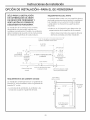
OPTION D'INSTALLATION--POUR GE MONOGRAM
INSTALLATION COMBINI_E DE LA TABLE
DE CUISSON A INDUCTION GE OU GE
MONOGRAM ET DE L'E×TRACTEUR 30"
L'installation de I'extrocteur avec cette table de
cuisson n#cessite une r#alisation soign#e. La table
de cuisson et I'extracteur doivent _tre install#s
conform#ment (_leurs instructions d'installation
respectives.
CONDITIONS REQUISES DU PLAN DE TRAVAIL
Le plan de travail dolt disposer d'une surface plate
et profonde pour accepter I'installation de la table
de cuisson et de I'extracteur. Les plans de travail
avec une bordure de champ arrondi (_I'avant et un
dosseret ne disposent de la surface plate requise.
, Consultez I'illustration pour d6terminer les
conditions requises du plan de travail.
- Tousles espaces libres de d6coupe pour cette
installation doivent 6tre respect6s.
4,4 cm (!-3/4") min. de la d_coupe de la table de
cuisson 6 la surface combustible verticale arri_re
91,7 cm (36-1/8")
91,4 cm (36")
552¢m -_ [
121-3/4") [ ',
deprofondeur 49,8cm ,
de d#coupe (19-5/8")de',
profondeur ',
de d#coupe ',
I pour Iotable',
de cu_son
86,3cm (34")ded#coupedela
tabledecuissonetdeI'extracteurt
2,6cm (1-1/32") au centre
6,3mm
.(1/4")overlap
3 mm
11/8")
d'espace
libre
58,4 cm (23") SS
58,1 cm (22-7/8")
de surface totale
plate n#cessaire
1
........... _ h ....
A
6,4cm (2-1/2")min. d'espace
Bordure avant du plan detravail Iibrejusqu'6 la d#coupe 5cm (2")min. de d6coupe
jusqu'au mur, des deux
c6t6s
CONDITIONS REOUISES DU MEUBLE SUPPORT
L'installation du combin6 peut se faire dans un
meuble support d'une profondeur standard de
61 cm (24"). Utilisez un meuble support d'au mains
91,4 cm (36") de large.
- Le Iogement de I'extracteur, le ventilateur et le
conduit occuperont I'int#rieur du meuble support.
6,4cm(2-1/2")jusqu'6
la d#coupe
I 2cm
(3/4'1
50,4 cm
(19-7/8")
t Extracteur
57,8cm(22-3/4'1int_rieur
55,9cm (22")jusqu'aurail
desupport
[
4,8 cm
1-7/8"
2cm(3/41
d'_paisseurdu
raildesupport
15

Instructions d'installation
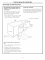
OPTIONS D'INSTALLATION
INSTALLATION DE LA TABLE DE
CUISSON AU-DESSUS D'UN FOUR
SIMPLE GE OU GE MONOGRAM
Ces tables de cuisson peuvent #tre install#es
au-dessus d'un four simple. La table de cuisson et
le four doivent #tre install#s conform#ment 6 leurs
instructions d'installation respectives.
- Laissez un espace libre minimal de 10 cm (4")
entre le haut du plan de travail et le haut de la
d#coupe du four.
ALIMENTATION I_LECTRIQUE
Le four n6cessite une alimentation ind#pendante,
correctement raccord#e 6 la terre de 20 amp#res, 6
trois ills de 208/240 V CA, 60 Hz. La table de cuisson
n#cessite une alimentation ind#pendante de 40
amp#res, 6 trois ills de 208/240 V CA, 60 Hz.
Tabledecuisson
59,7 cm
(23-1/2") min.
86 cm (33-7/8")
.... ::_< 48,5 cm
(19-1/8")
o - "
2 cm (3/4")
10 cm (4") de hauteur Plateforme
du coup-de-pied de support
requise
72,3cm
(28-1/2")min.
72,7cm
(28-5/8")max.
3,8cm(1-1/2"1du
hautdumeuble
6,4 cm
(2-1/2") min.
91,4cm136")
10cm (4")rain. dehauteurdu
plandetravail
69,2cm
(27-1/4")min.
69,3cm
(27-5/16")max.
Utilisez un meuble support d'au mains 91,4 cm (36")
de large.
. Pour une meilleure apparence, la table de cuisson
doit #tre centr#e au-dessus du four.
. Le d#flecteur du dessous de la table de cuisson
n'est pas n#cessaire pour cette installation
combin#e. Si le d#flecteur est en place, enlevez-le.
. Cette table de cuisson est approuv#e #tre
seulement install#e par-dessus les mod#les
sp@cifiques #num#r#s sur I'#tiquette de cette
unit#.
Lahauteurdolt
- correspondre6celle
ducoup-de-pied
16

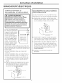
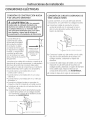
BRANCHEMENTS
Instructions d'instollotion
ELECTRIQUES
CONSTRUCTION NEUVE ET
RACCORDEMENT AU CIRCUIT Df_RIVI_
reccordement incorrect entre le cablege Ill
domestique en eluminium et les ills III
de sortie en cuivre peut provoquer un III
choc _lectrique ou un incendie. Utilisez Ill
uniquement des connecteurs condos pour III
roccorder du cuivre sur de I'oluminium et III
respectez scrupuleusement Io procedure III
Lors du roccordement des
ills, utilisez Io totolit6 de Io
Iongueur de cable fournie.
Le cable ne doit pos _tre
roccourci (souf si les
normes Iocoles I'exigent).
Lo Iongueur de cable est
de 1,2 m (4 pieds). Apr6s
ovoir instoll6 Io toble de
cuisson, ouvrez Io porte
ovont du meuble. Possez
les ills du cable 6 trovers
I'ouverture de Io boTte
40,6 cm
(16")Min.
Installez le bdtier
de d@rivation de
mani@re 6 pouvolr
I'atteindre par
I'avant du meuble.
]
de d6rivotion. Le serre-cable du posse-cable dolt
6tre correctement fix6 6 Io boTte de d6rivotion et le
cable souple dolt 6tre correctement ossujetti dons
le serre-cable.
• Lots de I'instollotion dons une construction
neuve ou
• Lors de I'instollotion dons une mobile-home ou
• Lors de I'instollotion dons un comping<or ou
• Lorsque les normes Iocoles ne permettent pos
un roccordement (_ Io terre (_trovers le neutre :
o. Ins6rez le cable (_trovers le posse-cable et
serrez.
b.
Fixez le fil de terre de I'opporeil (vert ou cuivre
d_nud_) conform_ment uux normes Iocoles.
Si le conducteur de terre du domicile est en
uluminium, voir I'AVERTISSEMENT.
Passe-c_ble __
, Fil de terre
Couvercle de k] boTtede
d6rivation
RACCORDEMENT AU CIRCUIT DI_RIVI_
TROIS CONDUCTEURS
Lors du branchement 6 un circuit d6riv_ 6 trois
conducteurs, si les normes Iocoles le permettent :
o. Branchez le conducteur vert de terre de la
table de cuisson avec le fil de terre serti (vert)
du circuit d6riv6 6 I'aide d'un serre-fils.
b_
C°
d°
L F_ilsde terre
et neutre
Couverde de k] boTte
de d6rivation
Branchez le fil rouge de la table de cuisson
au fil rouge du circuit d6riv6 conform6ment
aux normes locales, 6 I'aide d'un serre-fils.
Branchez le fil noir de la table de cuisson au
fil noir du circuit d6riv6 conform6ment aux
normes locales, 6 I'aide d'un serre-fils. Si les
ills de sortie rouge, noir ou blanc du domicile
sont des conducteurs en aluminium, voir
I'AVERTISSEMENT.
Installez le couvercle de la boTte de
d6rivation.
17

Instructions d'installation
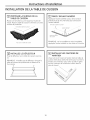
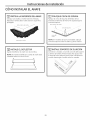
INSTALLATION DE LA TABLE DE CUISSON
r_ PROTI_GER LA SURFACE DE LA
TABLE DE CUISSON
Placez une serviette ou une nappe sur le plan de
travail. Posez la table de cuisson _ I'envers sur cette
surface de protection.
Fond de la table de cuisson
Tissu sous la table de cuisson
r_ FI×EZ L'ISOLANT
ADHI_SIF
Appliquez I'isolant adh#sif autour de la bordure
e×t#rieure de la vitre. Ne faites pas chevaucher
I'isolant adh#sif.
Fond de la table de cuisson
Isolant adh#sif ...........
'- -.
-. J/j/ _ /
aeCUlSSOn
REMARQUE sur les mod@les en acier inoxydable,
appliquez I'isolant adh6sif sur les c6t6s et _ I'arri@re.
[_] INSTALLEZ LE DI_FLECTEUR
Fi×ez le d#flecteur sur le table de cuisson avec les
vis.
REMARQUE"n'installez pas le d6flecteur Iorsque la
table de cuisson est positionn6e au-dessus d'un
four simple.
INSTALLEZ LES FIXATIONS DE
MAINTIEN
Vissez une vis 0 travers la fixation dans la table de
cuisson. (Des deu× c6t6s.) Ne serrez pas. Tournez la
fixation vers I'int#rieur pour 6viter qu'elle ne g#ne
lots de I'insertion de la table de cuisson dans le
plan de travail.
J
\
18

Instructions d'installation
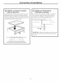
r_ INSleREZ LA TABLE DE CUISSON
DANS LA DI_COUPE
Ins@ez la table de cuisson centr6e dans I'ouverture
d6coup6e. Assurez-vous que la bordure avant du
plan de travail est parall61e _ la bordure de la table
de cuisson. Effectuez une derni@re v@rification sur la
conformit@ des espaces libres requis.
_] SERREZ LES FIXATIONS DE
P1AINTIEN AU P1EUBLE
Ouvrez la porte du meuble. Installez la deuxi_me
vis _ travers la fixation et serrez. Puis, serrez la
premi@e vis. Installez la vis papillon jusqu'_ ce
qu'elle touche le fond du plan de travail.
i
Tab edecu,sson
L
Plan de travail
IMPORTANT : vissez la vis papillon jusqu'8 ce qu'elle
touche le fond du plan de travail. Ne la vissez pas
en force.
19

Instructions d'installation
CHECK-LISTS
rT] CHECK-LIST DE PRI_TEST
E1
B]
Enlevez la totalit6 du film protecteur, si
applicable, et tousles autocollants.
Assurez-vous que tout le c_blage est bien fix6
sans pincement et qu'il n'est pas en contact
avec des pi6ces mobiles.
V6rifiez le nivellement de I'appareil.
V6rifiez que la table de cuisson est
correctement raccord6e 6 la terre.
[_] CHECK-LIST DE
FONCTIONNEMENT
[]
[]
[]
Enlevez tousles objets de la surface de la
table de cuisson.
Hettez sous tension la table de cuisson.
(Consultez votre manuel d'utilisation.) V6rifiez
que tousles br01eurs de surface fonctionnent
correctement.
V6rifiez que le disjoncteur du circuit n'est pas
d6clench6 et que le fusible domestique n'a
pas grill6.
V6rifiez que le c_ble est correctement
raccord6 6 la boTte de d@ivation.
Consultez le manuel d'utilisation pour la liste
de d6pannage.
REMARQUE A L'I_LECTRICIEN :
Les fils 6lectriques de sortie fournis avec I'appareil
sont conformes UL pour un raccordement _] un
c_blage domestique de grand calibre. L'isolant de
ces fils de sortie a 6t6 test6 6 des temp6ratures
largement sup6rieures (_celles observ6es sur
un circuit 61ectrique domestique. La capacit6 de
transport du courant d'un conducteur est r6gie
par le calibre du filet I'indice de temp6rature de
I'isolant autour du fil.
REMARQUE : CABLAGE EN ALUMINIUM
AVERTISSEMENT :
LE RACCORDEMENT INCORRECT D'UN
CIRCUIT DOMESTIQUE EN ALUMINIUM #,CES
FILS DE SORTIE EN CUIVRE PEUT PROVOQUER
UN GRAVE PROBLI_ME.
I_pissez les fils en cuivre sur les fils
en aluminium 6 I'aide de connecteurs
sp_cialement con_us et conformes UL pour
un branchement cuivre sur aluminium, et
respectez scrupuleusement la procedure
de raccordement recommand_e par le
fabricant.
REMARQUE : les fils utilis_s, l'emplacement
et l'isolation des _pissures, etc., doivent @ire
conformes _ la bonne pratique _lectrique et au×
normes locales.
2O
La page est en cours de chargement...
La page est en cours de chargement...
La page est en cours de chargement...
La page est en cours de chargement...
La page est en cours de chargement...
La page est en cours de chargement...
La page est en cours de chargement...
La page est en cours de chargement...
La page est en cours de chargement...
La page est en cours de chargement...
La page est en cours de chargement...
La page est en cours de chargement...
-
 1
1
-
 2
2
-
 3
3
-
 4
4
-
 5
5
-
 6
6
-
 7
7
-
 8
8
-
 9
9
-
 10
10
-
 11
11
-
 12
12
-
 13
13
-
 14
14
-
 15
15
-
 16
16
-
 17
17
-
 18
18
-
 19
19
-
 20
20
-
 21
21
-
 22
22
-
 23
23
-
 24
24
-
 25
25
-
 26
26
-
 27
27
-
 28
28
-
 29
29
-
 30
30
-
 31
31
-
 32
32


GE ZHU36RSR1SS Guide d'installation
- Taper
- Guide d'installation
- Ce manuel convient également à
dans d''autres langues
- English: GE ZHU36RSR1SS Installation guide
- español: GE ZHU36RSR1SS Guía de instalación
Documents connexes

Autres documents
-
KitchenAid GJD3044RB04 Guide d'installation
-
Kenmore 66544093501 Guide d'installation
-
Electrolux E36EC75DSS1 Guide d'installation
-
IKEA KECC562GBT05 Guide d'installation
-
Jenn-Air UXD8636DYS1 Le manuel du propriétaire
-
KitchenAid KODC304EBL00 Guide d'installation
-
Kenmore 66544052301 Guide d'installation
-
 CookTek MC1202S-200 Le manuel du propriétaire
