Jenn-Air JBR2088HES4 Le manuel du propriétaire
- Catégorie
- Frigos
- Taper
- Le manuel du propriétaire

THANK YOU for purchasing this high-quality product. If you should experience a problem not covered in TROUBLESHOOTING,
please visit our website at www.jennair.cem for additional information. If you still need assistance, call us at 1-800-688-1100. In
Canada, visit our website at www.jennair.ca or call us at 1-800-807-6777.
You will need your model and serial number located on the right-hand side of the refrigerator interior.
Para obtener acceso a "lnstrucciones para el usuario del refrigerador" en espaSol, o para obtener informaci6n adicional de su
producto, visite: www.jennair.com
Tenga listo su nQmero de modelo completo. Puede encontrar su nt3merode modelo y de serie en la etiqueta ubicada al lado
derecho del interior del refrigerador.
TableofContents/Tabledes mati@res
REFRIGERATOR SAFETY ................................................................... 1
INSTALLATION INSTRUCTIONS ....................................................... 2
REFRIGERATOR USE ....................................................................... 11
REFRIGERATOR CARE ..................................................................... 15
TROUBLESHOOTING ........................................................................ 16
WATER FILTER CERTIFICATIONS .................................................. 18
PRODUCT DATA SHEETS ................................................................ lg
WARRANTY ........................................................................................ 20
SleCURITle DU RleFRIGleRATEUR ................................................... 21
INSTRUCTIONS D'INSTALLATION ................................................. 22
UTILISATION DU RleFRIGleRATEUR ............................................... 31
ENTRETIEN DU RleFRIGleRATEUR ................................................. 35
DlePANNAGE ...................................................................................... 36
FEUlLLES DE DONNleES SUR LE PRODUIT .................................. 39
GARANTIE .......................................................................................... 40
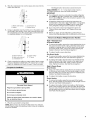
REFRIGERATORSAFETY
Your safety and the safety of others are very important.
We have provided many important safety messages in this manual and on your appliance. Always read and obey all safety
messages.
This is the safety alert symbol.
This symbol alerts you to potential hazards that can kill or hurt you and others.
All safety messages will follow the safety alert symbol and either the word "DANGER" or "WARNING."
These words mean:
You can be killed or seriously injured if you don't immediately
follow instructions.
You can be killed or seriously injured if you don't follow
instructions.
All safety messages will tell you what the potential hazard is, tell you how to reduce the chance of injury, and tell you what can
happen if the instructions are not followed.
W10137647A

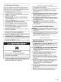
iMPORTANT SAFETY INSTRUCTIONS
WARNING: To reduce the risk of fire, electric shock, or injury to persons when using the refrigerator, follow basic precautions,
including the following:
• Plug into a grounded 3 prong outlet.
• Do not remove ground prong.
• Do not use an adapter.
• Do not use an extension cord.
• Disconnect power before servicing.
• Replace all parts and panels before operating.
• Remove doors from your old refrigerator.
• Use nonflammable cleaner.
• Keep flammable materials and vapors, such as gasoline,
away from refrigerator.
• Use two or more people to move and install refrigerator.
• Disconnect power before installing ice maker (on ice maker
kit ready models only).
SAVE THESE INSTRUCTIONS
ProperDisposalofYourOld Refrigerator
Suffocation Hazard
Remove doors from your old refrigerator.
Failure to do so can result in death or brain damage.
IMPORTANT: Child entrapment and suffocation are not problems
of the past. Junked or abandoned refrigerators are still dangerous
- even if they will sit for "just a few days." Ifyou are getting rid of
your old refrigerator, please follow these instructions to help
prevent accidents.
Before You Throw Away Your Old Refrigerator or Freezer:
• Take off the doors.
• Leave the shelves in place so that children may not easily
climb inside.
INSTALLATIONINSTRUCTIONS
Ive @e e
When Moving Your Refrigerator:
Excessive Weight Hazard
Use two or more people to move and install
refrigerator.
Failure to do so can result in back or other injury.
Your refrigerator is heavy. When moving the refrigerator
for cleaning or service, be sure to protect the floor.
Always pull the refrigerator straight out when moving it.
Do not wiggle or "walk" the refrigerator when trying to move
it, as floor damage could occur.
Remove the Packaging
• Remove tape and glue residue from surfaces before turning
on the refrigerator. Rub a small amount of liquid dish soap
over the adhesive with your fingers. Wipe with warm water
and dry.
• Do not use sharp instruments, rubbing alcohol, flammable
fluids, or abrasive cleaners to remove tape or glue. These
products can damage the surface of your refrigerator. For
more information, see "Refrigerator Safety."
• Dispose of/recycle all packaging materials.
Clean Before Using
After you remove all of the packaging materials, clean the inside of
your refrigerator before using it. See the cleaning instructions in
"Refrigerator Care."
important information to know about glass shelves
and covers:
Do not clean glass shelves or covers with warm water when
they are cold. Shelves and covers may break if exposed to
sudden temperature changes or impact, such as bumping.
For your protection, tempered glass is designed to shatter
into many small, pebble-size pieces. This is normal. Glass
shelves and covers are heavy. Use special care when
removing them to avoid impact from dropping.

Explosion Hazard
Keep tammable materials and vapors, such as
gasoline, away from refrigerator.
Failure to de so can result in death, explosion, or fire.
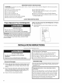
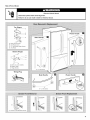
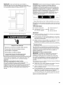
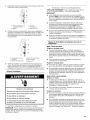
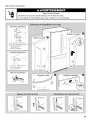
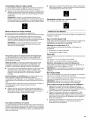
To ensure proper ventilation for your refrigerator, allow for a 1/211
(1.25 cm) space at the top and behind the refrigerator. If your
refrigerator has an ice maker, allow extra space at the back for the
water line connections. When installing your refrigerator next to a
fixed wall, leave 21/2'' (6.3 cm) minimum on the hinge side (some
models require more) to allow for the door to swing open.
NOTE: It is recommended that you do not install the refrigerator
near an oven, radiator, or other heat source. Do not install the
refrigerator in a location where the temperature will fall below 55°F
(13°C).
/
1/2" (1.2S cm) /
1[
/
21/2"(6.3 cm)
Electrical Shock Hazard
Plug into a grounded 3 prong outlet.
Do not remove ground prong.
Do not use an adapter.
Do not use an extension cord,
Failure to follow these instructions can result in death,
fire, or electrical shock.
Before you move your refrigerator into its final location, it is
important to make sure you have the proper electrical connection.
Recommended Grounding Method
A 115 Volt, 60 Hz., AC only 15- or 20-amp fused, grounded
electrical supply is required. It is recommended that a separate
circuit serving only your refrigerator be provided. Use an outlet
that cannot be turned off by a switch. Do not use an extension
cord.
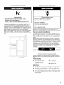
NOTE: Before performing any type of installation, cleaning, or
removing a light bulb, turn the refrigerator to OFR Depending on
your model, turn the freezer dial control to the word OFF,or press
the freezer Down Arrow control until a dash (-) appears in both the
Freezer and Refrigerator displays as shown. Disconnect the
refrigerator from the electrical source. When you are finished,
reconnect the refrigerator to the electrical source and reset the
temperature controls to the desired setting. See "Using the
Controls."
Gather the required tools and parts before starting installation.
Read and follow the instructions provided with any tools listed
here.
TOOLS NEEDED:
• Flat-blade screwdriver • 1/41Nut driver
• 7/161and 1/21Open-end or two • 1/41Drill bit
adjustable wrenches
• Cordless drill
IMPORTANT:
• All installations must meet local plumbing code requirements.
• Do not use a piercing-type or 3/16"(4.76 ram) saddle valve
which reduces water flow and clogs more easily.
• Use copper tubing and check for leaks. Install copper tubing
only in areas where the household temperatures will remain
above freezing.

Water Pressure
A cold water supply with water pressure of between 35 and
120 psi (241 and 827 kPa) is required to operate the water
dispenser and ice maker. If you have questions about your water
pressure, call a licensed, qualified plumber.
Reverse Osmosis Water Supply
IMPORTANT: The pressure of the water supply coming out of a
reverse osmosis system going to the water inlet valve of the
refrigerator needs to be between 35 and 120 psi (241 and
827 kPa).
If a reverse osmosis water filtration system is connected to your
cold water supply, the water pressure to the reverse osmosis
system needs to be a minimum of 40 to 60 psi (276 to 414 kPa).
If the water pressure to the reverse osmosis system is less than
40 to 60 psi (276 to 414 kPa):
• Check to see whether the sediment filter in the reverse
osmosis system is blocked. Replace the filter if necessary.
• Allow the storage tank on the reverse osmosis system to refill
after heavy usage.
• If your refrigerator has a water filter, it may further reduce the
water pressure when used in conjunction with a reverse
osmosis system. Remove the water filter. See "Water Filtration
System."
If you have questions about your water pressure, call a licensed,
qualified plumber.
_,.s_t::4_ _,,4_,,_ _÷
Read all directions before you begin.
IMPORTANT: Ifyou turn the refrigerator on before the water line is
connected, turn the ice maker OFR
Connect to Water Line
1. Unplug refrigerator or disconnect power.
2. Turn OFF main water supply. Turn ON nearest faucet long
enough to clear line of water.
3. Find a 1/2"to 11/4'' (12.7 mm to 3.18 mm) vertical cold water
pipe near the refrigerator.
IMPORTANT:
4.
5.
• Make sure it is a cold water pipe.
• Horizontal pipe will work, but the following procedure
must be followed: Drill on the top side of the pipe, not the
bottom. This will help keep water away from the drill. This
also keeps normal sediment from collecting in the valve.
Determine the length of copper tubing you need. Measure
from the connection on the lower right rear of refrigerator to
the water pipe. Add 7 ft (2.1 m) to allow for cleaning. Use 1/4"
(6.35 mm) O.D. (outside diameter) copper tubing. Be sure both
ends of copper tubing are cut square.
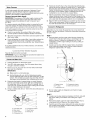
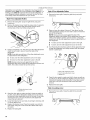
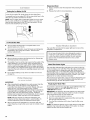
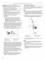
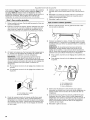
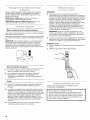
Using a cordless drill, drill a 1/4"hole in the cold water pipe you
have selected.
%
........ A
G
A. Cold waterpipe E.Compression sleeve
B. Pipe clamp E Shutoff valve
C. Copper tubing G.Packing nut
D. Compressionnut
6. Fasten the shutoff valve to the cold water pipe with the pipe
clamp. Be sure the outlet end is solidly in the 1/4"drilled hole in
the water pipe and that the washer is under the pipe clamp.
Tighten the packing nut. Tighten the pipe clamp screws slowly
and evenly so the washer makes a watertight seal. Do not
overtighten or you may crush the copper tubing.
7. Slip the compression sleeve and compression nut on the
copper tubing as shown. Insert the end of the tubing into the
outlet end squarely as far as it will go. Screw compression nut
onto outlet end with adjustable wrench. Do not overtighten.
8. Place the free end of the tubing in a container or sink, and turn
ON the main water supply. Flush the tubing until water is clear.
Turn OFF the shutoff valve on the water pipe.
Connect to Refrigerator
Depending on your model, the water line may come down from
the top or up from the bottom. Follow the connection instructions
for your model.
Style 1
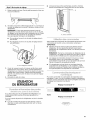
1. Remove plastic cap from water valve inlet port. Attach the
copper tube to the valve inlet using a compression nut and
sleeve as shown. Tighten the compression nut. Do not
overtighten. Confirm copper tubing is secure by pulling on
copper tubing.
2. Create a service loop with the copper tubing. Avoid kinks
when coiling the copper tubing. Secure copper tubing to
refrigerator cabinet with a "P" clamp.
B-- @
@
C
D i
I
A. Copper tubing D. Compression sleeve
B. "P" clamp E. Water valve inlet port
C. Compression nut
3. Turn on water supply to refrigerator and check for leaks.
Correct any leaks.
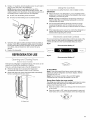
Style 2
1. Create a service loop (minimum diameter of 2ft [61 cm]) with
the copper tubing. Avoid kinks when coiling the copper
tubing.
2. Remove the plastic cap from water valve inlet port. Place a
compression nut and sleeve on the copper tubing.
3. Insert the end of the copper tubing into the water valve inlet
port. Shape tubing slightly so that the tubing feeds straight
into the port to avoid kinks.

4. Slidethecompressionnutoverthesleeveandscrewintothe
watervalveinletport.
5.
A. Plastic water tubing C. Compression nut
B.Sleeve D. Copper tubing
Using an adjustable wrench, hold the nut on the plastic water
line to keep it from moving. Then, with a second wrench turn
the compression nut on the copper tubing counterclockwise
to completely tighten. Do not overtighten.
A. Plastic water line D. Copper tubing
B. Water valve inlet port E. "P" clamp
C. Compression nut
6. Check connection by pulling on copper tubing. Attach copper
tubing to refrigerator cabinet with a "P" clamp. Turn on water
supply to refrigerator and check for leaks. Correct any leaks.
Complete the Installation
Electrical Shock Hazard
Plug into a grounded 3 prong outlet.
Do not remove ground prong.
Do not use an adapter.
Do not use an extension cord.
Failure to follow these instructions can result in death,
fire, or electrical shock.
1. Plug into a grounded 3 prong outlet.
NOTE: Allow 24 hours to produce the first batch of ice. Discard
the first three batches of ice produced. Allow 3 days to completely
fill the ice container.
TOOLS NEEDED: %6%%", W' hex-head socket wrench, a
#2 Phillips screwdriver, and a flat-blade screwdriver.
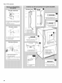
IMPORTANT:
• Your refrigerator may have a standard reversible refrigerator
door (Style 1) with either a freezer door or freezer drawer, or
French doors (Style 2). Follow the instructions specific to the
door style of your model,
• All graphics referenced in the following instructions are
included later in this section after "Final Steps." The graphics
shown for the standard door (Style 1) are for a right-hand
swing refrigerator (hinges factory installed on the right).
• If you only want to remove and replace the doors see
"Remove Doors and Hinges" and "Replace Doors and
Hinges."
• Before you begin, turn the refrigerator control OFF, and
remove food and adjustable door or utility bins from the doors,
Remove and Replace Refrigerator Door Handles
Style 1-Standard Door
Front Mount Handle
• To remove the handle, remove the screw attaching the trim to
the upper end of the handle. Using a flat-blade screw driver
wrapped in masking tape, pry the trim piece from the lower
end of the handle. Then, remove the screws attaching the
handle to the door. See Front Mount graphic 2.
• To replace handle, reverse directions.
Side Mount Handle
• To remove the handle, remove the four screws attaching the
handle to the side of the door. See Side Mount graphic 2.
• To replace the handle, align the holes in the handle with the
holes in the door. Then, insert a screw in the upper hole at
each end of the handle. Next, insert a screw in the lower
holes. Tighten the screws. See Side Mount graphic 2.
Style 2-French Doors
Metal Handles
• Using a ¾2" Allen wrench, loosen the two set screws located
on the side of each handle. Pull the handle straight out from
the door. Make sure you keep the screws for reattaching the
handles. See Metal Handle graphic 1.
• To replace the handles, reverse the directions.
Plastic Handles
• To remove the handle, grasp the lower part of the handle
firmly, slide the handle up and pull the handle straight out from
the door. See Plastic Handle graphic 1.
• To replace the handle, Position the handle so that the large
holes in the mounting clips are down and align the holes with
the door studs. Rotate the handle so that the mounting clips
are flat against the door and slide the handle down to engage.
See Plastic Handle graphic 1.

Remove Door and Hinges
Style 1-Standard Door
_6" Hex-Head Top Hinge Screw
Freezer drawer models
1. Unplug refrigerator or disconnect power.
2. Keep the refrigerator door closed until you are ready to lift it
free from the cabinet.
NOTE: Provide additional support for the door while the
hinges are being moved. Do not depend on the door gasket
magnets to hold the door in place while you are working.
3. Remove the parts for the top hinge as shown in Top Hinge
graphic. Lift the refrigerator door free from the cabinet.
4. Remove the parts for the bottom hinge as shown in Bottom
Hinge graphic.
Freezer door models
1. Unplug refrigerator or disconnect power.
2. Keep the freezer door closed until you are ready to lift it free
from the cabinet.
NOTE: Provide additional support for the door while the
hinges are being moved. Do not depend on the door gasket
magnets to hold the door in place while you are working.
3. Remove the parts for the top hinge as shown in Top Hinge
graphic. Lift the refrigerator door free from the cabinet.
4. Remove the center hinge pin and remove the hinge screws as
shown in the Center Hinge graphic. Lift the freezer door free
from the cabinet.
5. Remove the parts for the bottom hinge as shown in Bottom
Hinge graphic.
Style 2-French Doors
Electrical Shock Hazard
Disconnect power before removing doors.
Failure to do so can result in death or electrical shock.
1. Unplug refrigerator or disconnect power.
2. Keep the refrigerator doors closed until you are ready to lift
them free from the cabinet.
NOTE: Provide additional support for the refrigerator door
while the hinges are being removed. Do not depend on the
door gasket magnets to hold the door in place while you are
working.
3. Starting with the right-hand side door, remove the parts for the
top hinge as shown in Top Hinge graphic. Lift the refrigerator
door from the bottom hinge pin.
4. Remove the shim (on some models) from the bottom hinge pin
and keep it for later use. See Bottom Hinge graphic.
5. Before removing the left-hand side door, disconnect the wiring
plug located on top of the top hinge by wedging a flat-blade
screwdriver or your fingernail between the two sections. See
Wiring Plug graphic.
NOTE: The green, ground wire remains attached to the hinge.
6. Remove the parts for the left-hand side door top hinge as
shown in the Top Hinge graphic. Lift the door from the bottom
hinge pin.
NOTE: On some models, remove the shim from the bottom
hinge pin and keep it for later use. See Bottom Hinge graphic.
Reverse Door - Standard Door (optional)
IMPORTANT: If you want to reverse your door so it opens from
the opposite side, follow these steps. Ifyou are not reversing the
door, see "Replace Door and Hinges."
Door Stop Screw
Door Handle Seal Screw Front
Flat-Head Handle Screw
Cabinet Hinge Hole Plug
Cabinet
1. Remove hinge screws from handle side and move them to
opposite side. See Graphic 1-1.
2. Remove cabinet hinge hole plugs from cabinet top and move
them to opposite side hinge holes as shown in Graphic 1-2.
Refrigerator door
1. Remove the refrigerator handle assembly as shown in
Graphic 2. Keep all parts together.
2. Remove door handle seal screw front. Move to opposite side
of refrigerator door as shown in Graphic 6.
3. Remove the door stop. Move it to the opposite side of the
refrigerator door as shown in Graphic 4.
4. Attach the refrigerator handle to the opposite side of the
refrigerator door.
NOTE: For models with Front mount handles, replace the
handle trim as shown in Graphic 2.
5. Tighten all screws. Set aside the door until hinges and freezer
compartment door or drawer are in place.
Freezer door
1. Remove freezer handle assembly as shown. Keep all parts
together. See Graphic 5-1.
2. Remove freezer door handle seal screw. Move to opposite
side of freezer door.
3. Remove door stop. Move to opposite side of freezer door as
shown. See Graphic 4.
4. Attach handle to opposite side of freezer door.
5. Tighten all screws. Set aside door until bottom hinge is
installed on product.

Replace Door and Hinges
Style 1-Standard Door
NOTE: Graphics may be reversed if door swing is reversed,
Freezer drawer models
1. Replace the parts for the bottom hinge as shown. Tighten
screws.
NOTE: Provide additional support for the door while the
hinges are being moved. Do not depend on the door gasket
magnets to hold the door in place while you are working.
2. Assemble the parts for the top hinge as shown in Top Hinge
graphic. Do not tighten screws completely.
3. Adjust the door so that the bottom of the refrigerator door is
aligned with the top of the freezer drawer. Tighten all screws,
Freezer door models
1. Replace the parts for the bottom hinge as shown. Tighten
screws. Replace the freezer door.
NOTE: Provide additional support for the door while the
hinges are being moved. Do not depend on the door gasket
magnets to hold the door in place while you are working,
2. Assemble the parts for the center hinge as shown in the
Center Hinge graphic, and tighten all the screws. Replace the
refrigerator door.
3. Assemble the parts for the top hinge as shown in the Top
Hinge graphic. Do not tighten the screws completely.
4. Adjust the doors so that the bottom of the refrigerator door is
aligned with the top of the freezer door. Tighten all screws.
Style 2-French Doors
1. Assemble the parts for the top hinges as shown in Top Hinge
graphic. Do not tighten the screws completely.
2. Replace the parts for the bottom hinges as shown in Bottom
Hinge graphic. Tighten screws. Replace the refrigerator doors.
NOTE: Provide additional support for the refrigerator doors
while the hinges are being moved. Do not depend on the door
gasket magnets to hold the doors in place while you are
working.
3. Align each door so that the bottom of the refrigerator door
aligns evenly with the top of the freezer drawer. Tighten all
screws.
4. Reconnect the wiring plug on top of the left-hand side
refrigerator door.
5. Replace the top hinge covers.
Remove and Replace Freezer Drawer
• Two people may be required to remove and replace the freezer
drawer.
• All graphics are included later in this section after "Final
Steps."
Remove and Replace Drawer Handle
Metal Handles
• Using a %2" Allen wrench, loosen the two set screws located
on the side of each handle. Pull the handle straight out from
the drawer. Make sure you keep the screws for reattaching the
handles. See Metal Handle graphic 2.
• To replace the handle, reverse the directions.
Plastic Handles
• To remove the handle, grasp the handle firmly, slide the handle
to the left and pull the handle straight out from the drawer. See
Plastic Handle graphic 2.
• To replace the handle, Position the handle so that the large
holes in the mounting clips are to the right and align the holes
with the door studs. Rotate the handle so that the mounting
clips are flat against the drawer and slide the handle to the
right to engage. See Plastic Handle graphic 2.
Remove Drawer Front
1. Open the freezer drawer to full extension.
2. Loosen the four screws attaching the drawer glides to the
drawer front. See Drawer Front Removal graphic,
NOTE: Loosen screws three to four turns. Keep the screws in
the drawer front.
3. Lift drawer front upward and off the screws, See Drawer Front
Removal graphic.
Replace Drawer Front
1. Slide the drawer glides out of the freezer compartment. Insert
the screws in the top of the drawer front into the slots in the
drawer brackets. See Drawer Front Replacement graphic.
2. Pull the drawer brackets toward you to insert the two screws
in the bottom of the drawer front into the brackets, See
Drawer Front Replacement graphic.
3. Completely tighten the four screws.
Final Steps
1. Check all holes to make sure that hole plugs and screws are in
place, Reinstall top hinge cover as shown in Top Hinge
graphic.
Electrical Shock Hazard
Plug into a grounded 3 prong outlet.
Do not remove ground prong.
Do not use an adapter.
Do not use an extension cord.
Failure to follow these instructions can result in death,
fire, or electrical shock.
2. Plug in refrigerator or reconnect power.
3. Return all removable door parts to door and food to
refrigerator.

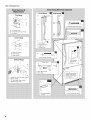
Style1-Standard Door
A. Top Hinge Cover
B. 5_6"Hex-Head Hinge Screws
C. Top Hinge
A. Hinge Pin Cover
B. Center Hinge
C. Hinge Screws
Bottom Hinge
D
A. Trim Screw
B. Handle Screws
C. Top Trim
D. Bottom Trim
A ............... _ |
-
A. Door Hinge Hole Plug
iiiiiiiiiiiiiiiiii
Front View
.I
A. Door Stop Screws
B. Door Stop
Side Mount
1st
3rd
2nd
4th
A. Cabinet Hinge Hole Plugs
A. 5_,, Hex-Head Hinge Screws
Door Handle
Seal Screw
Front
Some Standard Door
models have plastic
handles. See French
Doors graphic.
I
A Flat-Head Handle A Door Hinge Hole Plugs
Screws

Style 2-French Doors
Top Hinges
! A
B
, C
A. Hinge Cover Screw
B. Top Hinge Cover
C. 5/_6"Hex-Head Hinge Screws
D. Top Hinge
Bottom Hinges
A. Shim (on some models)
B. Bottom Hinge
C. Hinge Screws
Wiring Plug
Metal Handle
A. _/32"Set Screw
A
A. %2" Set Screw
//
//
//
//
//
//
//
//
,/
//
z/
/
Plastic Handle
®
Plastic Handle

Dependingonyourmodel,yourrefrigeratormayhavetwofront
adjustablerollers(Style1),orfouradjustablerollers(Style2),ora
levelingscrew(Style3)locatedatthebaseoftherefrigerator.If
yourrefrigeratorseemsunsteadyoryouwantthedoortoclose
moreeasily,followtheinstructionsforyourmodel.
Stylel-Two Adjustable Rollers
1. Remove the base grille. Grasp the grille firmly and pull it
toward you.
2. Remove the bracket cover. Insert the eraser end of a pencil in
the cover notch. Apply slight downward pressure to the
notched side of the cover while swinging it off.
3=
Using a screwdriver or %" hex driver, turn the roller adjustment
screw on each side to raise or lower that side of the
refrigerator.
NOTE: It may take several turns of the roller adjustment screw
to adjust the tilt of the refrigerator.
• To raise, turn the roller adjustment screw to the right.
• To lower, turn the roller adjustment screw to the left.
NOTE: Having someone push against the top of the
refrigerator takes some weight off the adjustment screws and
rollers. This makes it easier to turn the screws.
A. Roller adjustment screw
B. Brake foot
4. Open the door again to make sure that it closes as easily as
you like. If not, tilt the refrigerator slightly more to the rear by
turning both roller adjustment screws to the right. It may take
several more turns, and you should turn both adjustment
screws the same amount.
5. Lower the brake foot on each side, byturning it clockwise until
it is firmly against floor.
6. Replace the bracket cover. Place the bracket cover into the
outer edge, swing the cover toward the cabinet and snap it
into place.
7. Replace the base grille.
Style 2-Four Adjustable Rollers
1. Remove the base grille. Grasp the grille firmly and pull it
toward you.
2. Raise or lower the cabinet. Using a %" hex driver, turn the
roller adjustment screw(s) on each side to raise or lower that
side of the refrigerator.
NOTE: Having someone push against the top of the
refrigerator takes some weight off the adjustment screws and
rollers. This makes it easier to turn the screws. It may take
several turns of the roller adjustment screw to adjust the tilt of
the refrigerator.
• To raise, turn the roller adjustment screw to the right.
• To lower, turn the roller adjustment screw to the left.
3. Turn the brake foot clockwise until it is firmly against the floor
to keep the refigerator from rolling forward when the freezer
drawer is pulled open.
A. Rear roller adjustment screw
B. Front roller adjustment screw
C. Brake foot
4. Open the door again to make sure that it closes as easily as
you like. If not, tilt the refrigerator slightly more to the rear by
turning both leveling screws clockwise. It may take several
more turns, and you should turn both screws the same
amount.
5. Replace the base grille.
Style 3-Leveling screw
1. Remove the base grille. Grasp the grille firmly and pull it
toward you.
10

2=
Using a 1/4"hex driver, turn the leveling screw on each side to
raise or lower that side of the refrigerator.
NOTE: Having someone push against the top of the
refrigerator takes some weight off the leveling screws. This
makes it easier to turn the screws. It may take several turns of
the leveling screw to adjust the tilt of the refrigerator.
• To raise, turn the leveling screw clockwise.
• To lower, turn the leveling screw counterclockwise.
A. Leveling screw
3. Open the door again to make sure that it closes as easily as
you like. If not, tilt the refrigerator slightly more to the rear by
turning both leveling screws clockwise. It may take several
more turns, and you should turn both screws the same
amount.
4. Replace the base grille.
REFRIGERATORUSE
There are two refrigerator compartment doors. The doors can be
opened and closed either separately or together.
There is a vertically-hinged seal on the left refrigerator door.
• When the left side door is opened, the hinged seal
automatically folds inward so that it is out of the way.
• When both doors are closed, the hinged seal automatically
forms a seal between the two doors.
Your model may have either Electronic, Dial or Digital Controls.
IMPORTANT:
• Wait 24 hours for your refrigerator to cool completely before
adding food. Ifyou add food before the refrigerator has cooled
completely, your food may spoil.
NOTE: Adjusting the Refrigerator and Freezer Controls to a
higher (colder) than recommended setting will not cool the
compartments any faster.
• The recommended settings should be correct for normal
household refrigerator use. The controls are set correctly
when milk or juice is as cold as you like and when ice cream is
firm.
• If the temperature is too warm or too cold in the refrigerator or
freezer, first check the air vents to be sure they are not
blocked before adjusting the controls.
Eeclscx" c c £ 'sd Conffo s
For your convenience, the temperature contro(s are preset at the
factory. When you first install your refrigerator, make sure the
controls are still set to the recommended setting as shown.
Style 1
Recommended Setting "4"
Style 2
Recommended Setting "4"
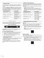
To Turn Off/On:
Style 1 Press the freezer Down Arrow control until a dash (-)
appears in both the refrigerator and freezer displays. Neither
compartment will cool.
Style 2 Turn the freezer control to the word OFR Neither
compartment will cool when the freezer is set to OFF.
Energy Saver Option (on some models)
The energy saver option turns off the heater which helps to reduce
moisture on the door hinge seal. The refrigerator uses more
energy when Energy Saver is off.
• Press the control to ON to save energy when the environment
is less humid.
• Press the control to OFF when the environment is warm and
more humid, or if you notice moisture on the door hinge seal.
EnelgySaver
A. Hinged seal
11

Adjusting Controls
If you need to adjust the temperature in either the refrigerator or
freezer compartment, use the settings listed in the chart below as
a guide.
To adjust the temperature, (Style 1} press the Up Arrow or Down
Arrow control, (Style 2) turn the dial to the desired setting. Except
when starting the refrigerator, do not adjust either control more
than one setting at a time. Wait 24 hours between adjustments for
the temperature to stabilize.
CONDITION/REASON: ADJUSTMENT:
REFRIGERATOR too warm REFRIGERATOR Control
one setting higher
FREEZER too warm/too little ice FREEZER Control one
setting higher
REFRIGERATOR too cold REFRIGERATOR Control
one setting lower
FREEZER too cold FREEZER Control one
setting lower
For your convenience, your temperature controls are preset at the
factory. When you first install your refrigerator, make sure the
controls are still set to the recommended set points as shown.
Recommended Settings
IMPORTANT: When the power is on, the temperature display
shows the actual temperature of the compartment.
To Turn Your Refrigerator Off/On:
• Press the freezer Up Arrow control repeatedly until "OFF"
appears in the freezer display. Allow a few seconds for the
refrigerator to shut off. Neither compartment will cool.
• Press either the refrigerator or freezer Up Arrow or Down
Arrow control to turn on the refrigerator.
Adjusting Digital Controls
The REFRIGERATOR control adjusts the refrigerator compartment
temperature. The FREEZER control adjusts the freezer
compartment temperature.
If you need to adjust the temperature in either the refrigerator or
freezer compartment, use the settings listed in the chart as a
guide.
To Adjust Set Point Temperatures:
The first touch of the Up Arrow or Down Arrow control displays
the current temperature set point. The display will show the set
point for approximately 3 seconds, and then return to the actual
temperature.
• Press the Up Arrow or Down Arrow control until the desired
temperature set point is displayed.
NOTE: Except when first turning on the refrigerator, do not
adjust either temperature control more than one setting at a
time. Wait 24 hours between adjustments for the temperature
to stabilize.
CONDITION/REASON: ADJUSTMENT:
REFRIGERATOR too warm Adjust REFRIGERATOR
Control 1° lower
FREEZER too warm/too little ice Adjust FREEZER
Control 1° lower
REFRIGERATOR too cold Adjust REFRIGERATOR
Control 1° higher
FREEZER too cold Adjust FREEZER
Control 1° higher
Additional Digital Control Center Features
Max Cool
The max cool feature assists with periods of high refrigerator use,
full grocery loads, or temporarily warm room temperatures.
• Press the Max Cool touch pad to set the freezer and
refrigerator to the lowest temperature settings. Press the Max
Cool touch pad again to return to the normal refrigerator set
point.
NOTE: The Max Cool feature will automatically shut off in
approximately 12 hours.
Speed Ice Feature
The Speed Ice feature assists with temporary periods of heavy ice
use by increasing ice production.
• Press the Speed Ice feature touch pad to set the freezer to the
lowest temperature setting. Press the Speed Ice feature touch
pad again to return to the normal freezer set point.
NOTE: When Speed Ice is on, neither the Up Arrow nor Down
Arrow control for the freezer will operate. The Speed Ice
feature will automatically shut off in approximately 24 hours.
12

Vacation Mode
In Vacation Mode, the freezer will not automatically defrost as
often to conserve energy.
• Press the Vacation Mode touch pad until the indicator light is
lit to turn on this feature. Press the Vacation Mode touch pad
again or open the refrigerator door to turn off this feature.
NOTE: The refrigerator door may be opened within 1 hour of
setting Vacation Mode without turning off the feature.
Temp Alarm
The Temp Alarm feature provides temperature information in the
event of a power outage.
Power outage: During a power outage, if the temperatures in the
refrigerator and freezer compartments exceed normal operating
temperatures, the highest temperature reached will be displayed.
• Press the Temp Alarm touch pad until the indicator light is lit,
to turn on this feature. Press and hold Temp Alarm for
3 seconds until the indicator light goes off to turn off this
feature.
Temperature alarm: An alarm will sound repeatedly if the freezer
or refrigerator compartment temperatures exceed normal
operating temperatures for an hour or more.
The temperature displays will alternately show the current
temperatures and the highest temperatures the compartments
reached.
• Press the Temp Alarm touch pad once to stop the audible
alarm and alternating temperature displays. The Temp Alarm
light will continue to flash until the refrigerator returns to the
set temperature.
[]
Door Alarm
The Door Alarm feature sounds a chime every few seconds when
the refrigerator door has been left open for 5 continuous minutes.
The chime will sound until the door is closed or Door Alarm is
turned off.
• Press the Door Alarm touch pad to turn this feature on or off.
The indicator light will be lit when the Door Alarm feature is on.
Water Filter Status Light and Filter Reset
(on some models)
See "WaterFiltration System"
Digital Control User Preferences
Thecontrol center allows you to set userpreferences, if desired.
Super Cool (CO)
This preference allows you to improve the air flow and
temperature control, To save energy, turn off this feature by
pressing OFR
Temperature Display (F_C)
This preference allows you to change the temperature display.
F - Temperature in degrees Fahrenheit
C - Temperature in degrees Celsius
Alarm (AL)
This preference allows you to turn off the sound of all alarms.
ON - You will hear the alarm sound.
OFF - You will not hear the alarm sound.
Auto Light Level Selection (LL)
This preference allows you to adjust the dispenser light level from
dimmest to brightest (settings 1 through 9).
NOTE: The Auto Light feature on the control center must be
selected to activate this preference.
Sabbath Mode (SAB)
ON - All control panel lights, interior lights and alarm tones will be
disabled.
OFF - All control panel lights, interior lights and alarm tones will be
enabled.
NOTE: Press the Door Alarm touch pad for 3 seconds to restore
all lights.
To Access the User Preferences Menu:
1. Press and hold the Door Alarm touch pad for 3 seconds. The
preference name will appear in the Freezer display and the
preference status (For C) or (ON or OFF) will appear in the
Refrigerator display.
2. Use the Freezer Up Arrow or Down Arrow control to scroll
through the preference names. When the desired preference
name is displayed, press the Refrigerator Up Arrow or Down
Arrow control to select the preference status.
3. Set your preferences by pressing and holding the Door Alarm
touch pad for 3 seconds, or by shutting the refrigerator
compartment door.
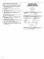
You can control the amount of humidity in the moisture-sealed
crispen Depending on your model, adjust the oontrol to any
setting between FRUIT and VEGETABLES or LOW and HIGH.
FRUIT / LOW (open) for best storage of fruits and vegetables with
skins.
VEGETABLES / HIGH (closed) for best storage of fresh, leafy
vegetables.
13

Turning the Ice Maker On/Off
Toturn the ice maker ON, simply lower the wire shutoff arm.
To manually turn the ice maker OFF, lift the wire shutoff arm to the
OFF (arm up) position and listen for the click.
NOTE: Your ice maker has an automatic shutoff. As ice is made,
the ice cubes will fill the ice storage bin and the ice cubes will
raise the wire shutoff arm to the OFF (arm up) position. Do not
force the wire shutoff arm up or down.
Dispensing Water
1. Hold a container under the dispenser while pressing the
button.
2. Release the button to stop dispensing.
Ice Production Rate
• The ice maker should produce a complete batch of ice
approximately every 3 hours.
• To increase ice production, lower the freezer and refrigerator
temperature. See "Using the Controls." Wait 24 hours
between adjustments.
Remember
• Allow 24 hours to produce the first batch of ice. Discard the
first three batches of ice produced.
• The quality of your ice will be only as good as the quality of the
water supplied to your ice maker. Avoid connecting the ice
maker to a softened water supply. Water softener chemicals
(such as salt) can damage parts of the ice maker and lead to
poor quality ice. If asoftened water supply cannot be avoided,
make sure the water softener is operating properly and is well
maintained.
• Do not store anything on top of the ice maker or in the ice
storage bin.
IMPORTANT:
• After connecting the refrigerator to a water source, flush the
water system. Press the button on the dispenser for
5 seconds, then release it for 5 seconds. Repeat until water
begins to flow. Once water begins to flow, continue
depressing and releasing the dispenser button (5 seconds on,
5 seconds off) for an additional 2 minutes. This will flush air
from the filter and water dispensing system. Additional
flushing may be required in some households. As air is cleared
from the system, water may spurt out of the dispenser.
NOTE: After five minutes of continuous dispensing, the
dispenser will stop dispensing water to avoid flooding. To
continue dispensing, press the dispenser button again.
• Allow 24 hours for the refrigerator to cool down and chill
water. Dispense enough water every week to maintain a fresh
supply.
The water filter is located in the upper right-hand corner of the
refrigerator compartment.
Do not use with water that is microbiologically unsafe or
of unknown quality without adequate disinfection before
or after the system. Systems certified for cyst reduction
may be used on disinfected waters that may contain
filterable cysts.
Water Filter Status Lights
The water filter indicator lights will remind you when it is time to
order and replace your water filter. When the yellow (Order) light is
on, it is almost time to change the water filter. When the red
(Replace) light is on, a new water filter should be installed. It is
recommended that you replace the water filter when the indicator
light changes to red OR earlier if the flow of water to your water
dispenser or ice maker decreases noticeably.
After replacing the water filter, press and hold the Reset Filter pad
for three seconds. The Order and Replace indicator lights will
blink and then go off when the system is reset.
Replacing the Water Filter
To purchase a replacement water filter, model UFK8001AXX-750,
contact your dealer or call 1-877-232-6771 U.S.A. or
1-800-807-6777 Canada.
IMPORTANT: Air trapped in the water system may cause water
and filter to eject. Always dispense water for at least 2 minutes
before removing the filter or blue bypass cap.
1. Turn filter counterclockwise to remove.
2. Remove sealing label from replacement filter and insert the
filter end into the filter head.
3. Turn the filter clockwise until it stops. Snap the filter cover
closed.
NOTE: The dispenser feature may be used without a water filter
installed. Your water will not be filtered. Ifthis option is chosen,
replace the filter with the blue bypass cap.
14

REFRIGERATORCARE
Explosion Hazard
Use nonflammable cleaner.
Failure to do so can result in death, explosion, or fire.
Both the refrigerator and freezer sections defrost automatically.
However, clean both sections about once a month to avoid
buildup of odors. Wipe up spills immediately.
IMPORTANT: Because air circulates between both sections, any
odors formed in one section will transfer to the other. You must
thoroughly clean both sections to eliminate odors. To avoid odor
transfer and drying out of food, wrap or cover foods tightly.
To Clean Your Refrigerator:
NOTE: Do not use abrasive or harsh cleaners such as window
sprays, scouring cleansers, flammable fluids, cleaning waxes,
concentrated detergents, bleaches or cleansers containing
petroleum products on plastic parts, interior and door liners or
gaskets. Do not use paper towels, scouring pads, or other harsh
cleaning tools.
1. Unplug refrigerator or disconnect power.
2. Hand wash, rinse, and dry removable parts and interior
surfaces thoroughly. Use a clean sponge or soft cloth and a
mild detergent in warm water.
3. Wash stainless steel and painted metal exteriors with a clean
sponge or soft cloth and a mild detergent in warm water.
• To keep your stainless steel refrigerator looking like new
and to remove minor scuffs or marks, it is suggested that
you use the manufacturer's approved Stainless Steel
Cleaner & Polish, Part Number 20000008. To order the
cleaner, call 1-877-232-6771 U.S.A. or 1-800-807-6777
Canada.
4.
IMPORTANT: This cleaner is for stainless steel parts only!
Do not allow the Stainless Steel Cleaner & Polish to come into
contact with any plastic parts such as the trim pieces,
dispenser covers or door gaskets. If unintentional contact
does occur, clean plastic part with a sponge and mild
detergent in warm water. Dry thoroughly with a soft cloth.
There is no need for routine condenser cleaning in normal
home operating environments. If the environment is
particularly greasy or dusty, or there is significant pet traffic in
the home, the condenser should be cleaned every 2 to
3 months to ensure maximum efficiency.
If you need to clean the condenser:
• Removethe base grille.
• Use a vacuum cleaner with a soft brush to clean the grille,
the open areas behind the grille and the front surface area
of the condenser.
• Replace the base grille when finished.
5. Plug in refrigerator or reconnect power.
NOTE: Not all appliance bulbs will fit your refrigerator. Be sure to
replace the bulb with an appliance bulb of the same size, shape,
and wattage (no greater than 40 watts).
1. Unplug the refrigerator or disconnect power.
2. Remove the light shield, if necessary.
Freezer drawer models
Top of the refrigerator compartment - Slide the light shield
toward the back of the compartment to release it from the
light assembly.
Top of freezer compartment - The light shield opens from
the back. Firmly press forward on the notches in the back
of the shield and pull the shield down.
NOTE: You may need to remove the upper freezer shelf or
basket to access the light assembly.
Freezer door models
• Top of the refrigerator compartment - Slide the shield
toward the back to release it from the light assembly.
• Top of freezer compartment - Squeeze and pull rear of
light shield toward you to release the tabs, then pull down.
3. Replace the burned-out bulb(s) with an appliance bulb(s) no
greater than 40 watts.
4. Replace the light shield.
Freezer drawer models
5.
• Top of the refrigerator compartment - insert the tabs on
the shield into the liner holes on each side of light
assembly. Slide the shield toward the front until it locks
into place.
NOTE: To avoid damaging the light shield, do not force
the shield beyond the locking point.
• Top of the freezer compartment - Insert the front tabs of
the shield into the liner and snap the back portion of the
shield over the light assembly.
Freezer door models
• Top of the refrigerator compartment - Insert the tabs on
the shield into the liner holes on each side of the light
assembly. Slide the shield toward the front until it locks.
NOTE: To avoid damaging the light shield, do not force
the shield beyond the locking point.
• Top of freezer compartment - Insert front tabs of light
shield into liner and snap the back of the shield over light
assembly.
Plug in refrigerator or reconnect power.
15

TROUBLESHOOTING
Firsttry the solutions suggested here or visit our website and reference FAQs (Frequently Asked Questions)
to possibly avoid the cost of a service call.
In the U.S.A., www.jennair.com In Canada, www.jennair.ca
The refrigerator will not operate
Electrical Shock Hazard
Plug into a grounded 3 prong outlet.
Do not remove ground prong.
Do not use an adapter.
Do not use an extension cord.
Failure to follow these instructions can result in death,
fire, or electrical shock.
• Power cord unplugged? Plug into a grounded 3 prong outlet,
• Is outlet working? Plug in a lamp to see if the outlet is
working,
• Household fuse blown or circuit breaker tripped? Replace
the fuse or reset the circuit breaker.
Are controls on? Make sure the refrigerator controls are on,
See "Using the Controls."
New installation? Allow 24 hours following installation for the
refrigerator to cool completely.
NOTE: Adjusting the temperature controls to coldest setting
will not cool either compartment more quickly.
The motor seems to run too much
Your new refrigerator may run longer than your old one due to its
high-efficiency compressor and fans. The unit may run even
longer if the room is warm, a large food load is added, doors are
opened often, or if the doors have been left open.
The refrigerator seems noisy
Refrigerator noise has been reduced over the years. Due to this
reduction, you may hear intermittent noises from your new
refrigerator that you did not notice from your old model. Below are
listed some normal sounds with explanations.
• Buzzing - heard when the water valve opens to fill the ice
maker
• Pulsating - fans/compressor adjusting to optimize
performance
• Hissing/Rattling - flow of refrigerant, movement of water
lines, or from items placed on top of the refrigerator
• Sizzling/Gurgling - water dripping on the heater during
defrost cycle
• Popping - contraction/expansion of inside walls, especially
during initial cool-down
• Water running - may be heard when water melts during the
defrost cycle and runs into the drain pan
• Creaking/Cracking - occurs as ice is being ejected from the
ice maker mold,
The doors will not close completely
• Door blocked open? Move food packages away from door.
• Bin or shelf in the way? Push bin or shelf back in the correct
position.
The doors are difficult to open
Explosion Hazard
Use nonflammable cleaner.
Failure to do so can result in death, explosion, or fire.
• Gaskets dirty or sticky? Clean gaskets and contact surfaces
with mild soap and warm water. Rinse and dry with soft cloth.
16

Temperature is too warm
• New installation? Allow 24 hours following installation for the
refrigerator to cool completely.
• Door(s} opened often or left open? Allows warm air to enter
refrigerator. Minimize door openings and keep doors fully
closed.
• Large load of food added? Allow several hours for
refrigerator to return to normal temperature.
• Controls set correctly for the surrounding conditions?
Adjust the controls a setting colder. Check temperature in
24 hours. See "Using the Controls."
There is interior moisture buildup
NOTE: Some moisture buildup is normal.
• Humid room? Contributes to moisture buildup.
• Door(s) opened often or left open? Allows humid air to enter
refrigerator. Minimize door openings and keep doors fully
closed.
ce p_-w' a ¢+ e_,"
The ice maker is not producing ice or not enough ice
• Refrigerator connected to a water supply and the supply
shutoff valve turned on? Connect refrigerator to water
supply and turn water shutoff valve fully open.
• Kink in the water source line? A kink in the line can reduce
water flow. Straighten the water source line.
• Ice maker turned on? Make sure wire shutoff arm or switch
(depending on model) is in the ON position.
• New installation? Wait 24 hours after ice maker installation
for ice production to begin. Wait 72 hours for full ice
production.
• Freezer door closed completely? Firmly close the freezer
compartment door. If the freezer compartment door will not
close all the way, see "The doors will not close completely."
• Large amount of ice recently removed? Allow 24 hours for
ice maker to produce more ice.
• Ice cube jammed in the ice maker ejector arm?
Remove ice from the ejector arm with a plastic utensil.
• Water filter installed on the refrigerator? Remove filter and
operate ice maker. If ice volume improves, then the filter may
be clogged or incorrectly installed. Replace filter or reinstall it
correctly.
• Reverse osmosis water filtration system connected to
your cold water supply? This can decrease water pressure.
See "Water Supply Requirements."
The ice cubes are hollow or small
NOTE: This is an indication of low water pressure.
• Water shutoff valve not fully open? Turn the water shutoff
valve fully open.
• Kink in the water source line? A kink in the line can reduce
water flow. Straighten the water source line.
• Water filter installed on the refrigerator? Remove filter and
operate ice maker. If ice quality improves, then the filter may
be clogged or incorrectly installed. Replace filter or reinstall it
correctly.
• Reverse osmosis water filtration system connected to
your cold water supply? This can decrease water pressure.
See "Water Supply Requirements."
• Questions remain regarding water pressure? Call a
licensed, qualified plumber.
Off-taste, odor or gray color in the ice
• New plumbing connections? New plumbing connections
can cause discolored or off-flavored ice.
• Ice stored too long? Discard ice. Wash ice bin. Allow
24 hours for ice maker to make new ice.
• Odor transfer from food? Use airtight, moisture proof
packaging to store food.
• Are there minerals (such as sulfur) in the water? A water
filter may need to be installed to remove the minerals.
• Water filter installed on the refrigerator? Gray or dark
discoloration in ice indicates that the water filtration system
needs additional flushing. Flush the water system before using
a new water filter. Replace water filter when indicated. See
"Water Filtration System."
The water dispenser will not operate properly
• Refrigerator connected to a water supply and the supply
shutoff valve turned on? Connect refrigerator to water
supply and turn water shutoff valve fully open.
• Kink in the water source line? Straighten the water source
line.
• New installation? Flush and fill the water system. See "Water
Dispenser."
• Is the water pressure at least 35 psi (241 kPa}? The water
pressure to the home determines the flow from the dispenser.
See "Water Supply Requirements."
• Water filter installed on the refrigerator? Remove filter and
operate dispenser. If water flow increases, the filter may be
clogged or incorrectly installed. Replace filter or reinstall it
correctly.
• Refrigerator door closed completely? Close the door firmly.
If it does not close completely, see "The doors will not close
completely."
• Recently removed the doors? Make sure the water
dispenser wire/tube assembly has been properly reconnected
at the bottom of the refrigerator door. See "Refrigerator
Doors."
• Reverse osmosis water filtration system connected to
your cold water supply? This can decrease water pressure.
See "Water Supply Requirements."
17

Water is leaking from the dispenser system
NOTE: One or two drops of water after dispensing is normal.
• Glass not being held under the dispenser long enough?
Hold the glass under the dispenser 2 to 3 seconds after
releasing the dispenser lever.
• New installation? Flush the water system. See "Water
Dispenser."
• Recently changed water filter? Flush the water system. See
"Water Dispenser."
• Water on the floor near the base grille? Make sure the water
dispenser tube connections are fully tightened. See
"Refrigerator Doors."
Water from the dispenser is warm
NOTE: Water from the dispenser is only chilled to 50°F (10°C).
• New installation? Allow 24 hours after installation for the
water supply to cool completely.
• Recently dispensed large amount of water? Allow 24 hours
for water supply to cool completely.
• Water not been recently dispensed? The first glass of water
may not be cool. Discard the first glass of water.
• Refrigerator connected to a cold water pipe? Make sure
the refrigerator is connected to a cold water pipe. See "Water
Supply Requirements."
WATERFILTER
CERTIFICATIONS
Sta(e of Cahfomia
Departmem of Ilealth Services
WaterTreatmentDevice
CertificateNumber
03- 1583
Date l_sued September 16 2003
Date Revised April ?2 ?(KJ4
Trademark/Model Des_Qnation RePlacement Element_
UKFg001AXX750 UKF80{ IAXX
46qd06-750
67003523-750
Manufacturer: P_'_Pu_ _lc
Rated Service Capacity: 750 gaI Rated Service Flow: 07g gpm
Conditions of Certification:
Do _ot ilse w_ere water is mic_obiologic,q/y _msafe or with water of imknow_ quality, e_cept that _ystems certified for
cys_ reductio_ m,_y be used o_ disinfected waters that may contain fi)terable cysts
18

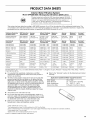
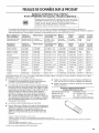
PRODUCTDATA SHEETS
Interior Water Filtration System
Model UFK8001AXX-750 Capacity 750 Gallons (2839 Liters)
I ystem tested and certified by NSF International against NSF/ANSI
(_ Standard 42 for the reduction of Chlorine Taste and Odor, Particulate
Class I*; and against NSF/ANSl Standard 53 for the reduction of
Lead, Mercury, Atrazine, Benzene, p-Dichlorobenzene, Carbofuran,
Toxaphene, Cysts, Turbidity, Asbestos and Lindane.
This system has been tested according to NSF/ANSl Standards 42 and 53 for the reduction of the substances listed below. The
concentration of the indicated substances in water entering the system was reduced to a concentration less than or equal to the
permissible limit for water leaving the system, as specified in NSF/ANSI Standards 42 and 53.
Substance Reduction NSF Reduction Average Influent Challenge Maximum Average Minimum% Average%
Aesthetic Effects Requirements Influent Concentration Effluent Effluent Reduction Reduction
Chlorine Taste/Odor 50% reduction 1.88 mg/L 2.0 mg/L _+10% 0.06 mg/L ** 0.05 rng/L 96.84 >97.26
Particulate Class I* 85% reduction 5,700,000 #/mL Atpar_icles/mLleast10,000 69,000 #/mL 30,583 #/mL 98.94 99.52
Contaminant NSF Reduction Average Influent Challenge Maximum Average Minimum% Average%
Reduction Requirements Influent Concentration Effluent Effluent Reduction Reduction
Lead: (®pH 6.5 0.010 mg/L 0.153 mg/L _ 0.15 mg/L _+10% < 0.001mg/L < 0.001mg/L >99.29% >99.35%
Lead: @pH 8.5 0.010 mg/L 0.150 mg/L t 0.15 mg/L _+10% < 0.001mg/L < 0.001mg/L >99.29% >99.33%
Mercury: @ pH 6.5 0.002 mg/L 0.006 mg/L 0.006 mg/L _+10% 0.0005 mg/L 0.0003 mg/L 90.91 95.70
Mercury: @ pH 8.5 0.002 mg/L 0.006 mg/L 0.006 mg/L _+10% 0.0015 mg/L 0.0008 mg/L 75.93 86.22
Benzene 0.005 mg/L 0.014 mg/L 0.015 mg/L _+10% 0.0011 mg/L 0.0006 mg/L 92.14% 95.71%
p-Dichlorobenzene 0.075 mg/L 0.208 mg/L 0.225 mg/L _+10% < 0.0005 mg/L < 0.0005 mg/L 99.74% 99.76%
Carbofuran 0.04 mg/L 0.081 mg/L 0.08 mg/L _+10% < 0.001mg/L < 0.001mg/L 98.46% 98.74%
Toxaphene 0.003 mg/L 0.015 mg/L 0.015 _+10% < 0.001mg/L < 0.001mg/L 91.67% 92.97%
Atrazine 0.003 mg/L 0.009mg/L 0.009 mg/L _+10% < 0.002 mg/L < 0.002 mg/L 75.31% 76.99%
Asbestos 99% 155 MF/L 107to 108fibers/L tt < 1 MF/L < 1 MF/L >99.99% >99.99%
Live Cysts _ >99.95% 166,500 #/L 50,000/L min. < 1 #/L_ < 1 #/L_ >99.99 >99.99
Turbidity 0.5 NTU 10.7 NTU 11 _+1 NTU 0.49 NTU 0.31 NTU 95.2 97.09
Lindane 0.0002 mg/L 0.002 mg/L 0.002 _+10% < 0.0001mg/L 0.000 mg/L 96.50% 98.72%
Test Parameters: pH = 7.5 + 0.5 unless otherwise noted. Flow = 0.78 gpm (1.9 Lpm). Pressure = 60 psig (413.7 kPa). Temp. = 68°F to
71.6°F (20°C to 22°C).
• It is essential that operational, maintenance, and filter
replacement requirements be carried out for the product to
perform as advertised.
• The filter monitor system measures the amount of water that
passes through the filter and alerts you to replace the filter.
When 90% of the filter's rated life is used, the yellow (Order)
light comes on. When 100% of the filter's rated life is used, the
red (Replace) light comes on, and it is recommended that you
replace the filter. For models without filter status lights,
replace the filter every 6 months. Use replacement filter
model UFK8001AXX-750. 2007 suggested retail price of
$49.99 U.S.A./S65.95 Canada. Prices are subject to change
without notice.
• The product is for cold water use only.
• Do not use with water that is microbiologically unsafe or of
unknown quality without adequate disinfection before or after
the system. Systems certified for cyst reduction may be used
on disinfected waters that may contain filterable cysts.
• Refer to the "Water Filtration System" section for the
Manufacturer's name and telephone number.
• Refer to the "Warranty" section for the Manufacturer's limited
warranty.
Application Guidelines/Water Supply Parameters
Water Supply City or Well
Water Pressure 35 - 120 psi (241 - 827 kPa)
Water Temperature 33 ° - 100°F (1° - 38°C)
Service Flow Rate 0.78 gpm (2.9 L/min.) @ 60 psi.
*Class I particle size: >0.5 to <1 um
**Test requirement is at least 100,000 particles/mL of AC Fine Test Dust.
tThese contaminants are not necessarily in your water supply. Performance may vary based on local water conditions.
ttFibers greater than 10 um in length
_Based on the use of Cryptosporidium parvum oocysts
® NSF is a registered trademark of NSF International.
19

JENN-AIR REFRIGERATORWARRANTY
ONE YEAR LIMITED WARRANTY
For one year from the date of purchase, when this major appliance is operated and maintained according to instructions attached to or
furnished with the product, Jenn-Air brand of Maytag Corporation or Maytag Limited (hereafter "Jenn-Air") will pay for factory specified
replacement parts and repair labor to correct defects in materials or workmanship. Service must be provided by a Jenn-Air designated
service company. This limited warranty applies only when the major appliance is used in the country in which it is purchased.
On models with a water filter: 30 day limited warranty on water filter. For 30 days from the date of purchase, when this filter is operated
and maintained according to instructions attached to or furnished with the product, Jenn-Air will pay for replacement parts to correct
defects in materials and workmanship.
SECOND THROUGH FIFTH YEAR LIMITED WARRANTY ON CAVITY LINER AND SEALED REFRIGERATION SYSTEM PARTS
In the second through fifth years from the date of purchase, when this major appliance is operated and maintained according to
instructions attached to or furnished with the product, Jenn-Air will pay for replacement or repair of the refrigerator/freezer cavity liner
(including labor costs) if the part cracks due to defective materials or workmanship. Also, in the second through fifth years from the date
of purchase, Jenn-Air will pay for factory specified parts and labor to correct defects in materials or workmanship in the sealed
refrigeration system. These parts are: compressor, evaporator, condenser, dryer, and connecting tubing. Service must be provided by a
Jenn-Air designated service company.
ITEMS JENN-AIR WILL NOT PAY FOR
1. Service calls to correct the installation of your major appliance, to instruct you how to use your major appliance, to replace or repair house
fuses or to correct house wiring or plumbing.
2. Service calls to repair or replace appliance light bulbs, air filters or water filters. Those consumable parts are excluded from warranty
coverage.
3. Repairs when your major appliance is used for other than normal, single-family household use.
4. Damage resulting from accident, alteration, misuse, abuse, fire, flood, acts of God, improper installation, installation not in accordance with
electrical or plumbing codes, or use of products not approved by Jenn-Air.
5. Any food loss due to refrigerator or freezer product failures.
6. Replacement parts or repair labor costs for units operated outside the United States or Canada.
7. Pickup and delivery. This major appliance is designed to be repaired in the home.
8. Repairs to parts or systems resulting from unauthorized modifications made to the appliance.
9. Expenses for travel and transportation for product service in remote locations.
10. The removal and reinstallation of your appliance if it is installed in an inaccessible location or is not installed in accordance with published
installation instructions.
11. Replacement parts or repair labor costs when the major appliance is used in a country other than the country in which it was purchased.
DISCLAIMER OF IMPLIED WARRANTIES; LIMITATION OF REMEDIES
CUSTOMER'S SOLE AND EXCLUSIVE REMEDY UNDER THIS LIMITED WARRANTY SHALL BE PRODUCT REPAIR AS PROVIDED
HEREIN. IMPLIED WARRANTIES, INCLUDING WARRANTIES OF MERCHANTABILITY OR FITNESS FOR A PARTICULAR PURPOSE,
ARE LIMITED TO ONE YEAR OR THE SHORTEST PERIOD ALLOWED BY LAW. JENN-AIR SHALL NOT BE LIABLE FOR INCIDENTAL
OR CONSEQUENTIAL DAMAGES. SOME STATES AND PROVINCES DO NOT ALLOW THE EXCLUSION OR LIMITATION OF
INCIDENTAL OR CONSEQUENTIAL DAMAGES, OR LIMITATIONS ON THE DURATION OF IMPLIED WARRANTIES OF
MERCHANTABILITY OR FITNESS, SO THESE EXCLUSIONS OR LIMITATIONS MAY NOT APPLY TO YOU. THIS WARRANTY GIVES
YOU SPECIFIC LEGAL RIGHTS AND YOU MAY ALSO HAVE OTHER RIGHTS, WHICH VARY FROM STATETO STATE OR PROVINCE
TO PROVINCE.
Outside the 50 United States and Canada, this warranty does not apply. Contact your authorized Jenn-Air dealer to determine if another
warranty applies. 5/07
For additional product information, in the U.S.A., visit www.jennair.com
In Canada, visit www.jennair.ca
If you do not have access to the Internet and you need assistance using your product or you would like to schedule service, you may
contact Jenn-Air at the number below.
Have your complete model number ready. You can find your model number and serial number on the label located on the right-hand
side of the refrigerator interior.
For assistance or service in the U.S.A., call 1-800-688-1100. In Canada, call 1-800-807-6777.
If you need further assistance, you can write to Jenn-Air with any questions or concerns at the address below:
In the U.S.A.: In Canada:
Jenn-Air Brand Home Appliances Jenn-Air Brand Home Appliances
Customer eXperience Center Customer Interaction Centre
553 Benson Road 1901 Minnesota Court
Benton Harbor, MI 49022-2692 Mississauga, Ontario L5N 3A7
Please include a daytime phone number in your correspondence.
Please keep this User Instructions and model number information for future reference.
2O
La page charge ...
La page charge ...
La page charge ...
La page charge ...
La page charge ...
La page charge ...
La page charge ...
La page charge ...
La page charge ...
La page charge ...
La page charge ...
La page charge ...
La page charge ...
La page charge ...
La page charge ...
La page charge ...
La page charge ...
La page charge ...
La page charge ...
La page charge ...
-
 1
1
-
 2
2
-
 3
3
-
 4
4
-
 5
5
-
 6
6
-
 7
7
-
 8
8
-
 9
9
-
 10
10
-
 11
11
-
 12
12
-
 13
13
-
 14
14
-
 15
15
-
 16
16
-
 17
17
-
 18
18
-
 19
19
-
 20
20
-
 21
21
-
 22
22
-
 23
23
-
 24
24
-
 25
25
-
 26
26
-
 27
27
-
 28
28
-
 29
29
-
 30
30
-
 31
31
-
 32
32
-
 33
33
-
 34
34
-
 35
35
-
 36
36
-
 37
37
-
 38
38
-
 39
39
-
 40
40


Jenn-Air JBR2088HES4 Le manuel du propriétaire
- Catégorie
- Frigos
- Taper
- Le manuel du propriétaire
dans d''autres langues
- English: Jenn-Air JBR2088HES4 Owner's manual