Modern Forms PD-53728 Catalyst Mode d'emploi
- Taper
- Mode d'emploi

1Modern Forms retains the right to modify the design of our products at any time as part of the company's continuous improvement program.
modernforms.com
Phone (800) 526.2588
Fax (800) 526.2585
Headquarters/Eastern Distribution Center
44 Harbor Park Drive
Port Washington, NY 11050
Central Distribution Center
1600 Distribution Ct
Lithia Springs, GA 30122
Western Distribution Center
1750 Archibald Avenue
Ontario, CA 91760
HARDWARE
WARNING
IMPORTANT: NEVER attempt any work without shutting o the electricity.
- Read all instructions before installing.
- System is intended for installation by a qualied electrician in accordance with the National Electrical Code and local regulations.
- Go to the main fuse box, or circuit breaker. Place the main power switch in the “OFF” position and unscrew the fuse(s) or switch ”OFF”
the circuit breaker switch(es) that control the power to the xture or room that you are working on.
- Place the wall switch in the “OFF” position.
CAUTION
- All parts must be used as indicated in these instructions. Do not substitute any parts, leave parts out, or use any parts that are
worn out or broken. Failure to follow this instruction could invalidate the ETL/CETL listing of this xture.
CAUTION When handling the xture, do not apply pressure to the LEDs. Hold the xture by the base only.
AVERTISSEMENT
IMPORTANT : Coupez l’électricité avant TOUTE manipulation.
- Lisez toutes les instructions avant d’installer.
- Système est destiné à être installé par un électricien qualié en conformité avec le code national de l’électricité et les
règlements locaux.
- Accédez au panneau central de disjoncteurs ou de fusibles de votre demeure et placez l’interrupteur principal en position d’arrêt
(« OFF »).
- Placez l’interrupteur mural en position d’arrêt (« OFF »).
MISE EN GARDE
- Toutes les pièces doivent être utilisées tel qu’il est indiqué dans ces instructions. Ne remplacez pas les pièces, n’en laissez pas de côté
et ne les utilisez pas si elles sont usées ou brisées. Le non-respect de ces instructions peut annuler l’homologation ETL/CETL du
luminaire. MISE EN GARDE Ors de la manipulation de l’appareil, ne pas appliquer de pression à la LED, tenir l’appareil par la seule base.
ADVERTENCIA
IMPORTANTE: NUNCA intente hacer trabajos sin desconectar el suministro eléctrico.
- Lea y comprenda todas las instrucciones e ilustraciones por completo antes de proceder con el ensamblaje e insta lación de esta
lámpara.
- Sistema está disenado para ser instalado por un electricista calicado, de acuerdo con el código eléctrico nacional y las normas locales.
- Diríjase a la caja de fusibles o a la caja del interruptor de circuito principal en su hogar. Coloque el interruptor de ali mentación
principal en la posición “OFF” (APAGADO).
- Coloque el interruptor de la pared en la posición “OFF” (APAGADO).
PRECAUCIÓN
- Todas las piezas deben usarse como lo indican estas instrucciones. No reemplace las piezas, noomita piezas durante la instalación ni
utilice piezas gastadas o rotas. El incumplimiento de esta indicación podría invalidar la calicación
ETL/CETL esta lámpara. PRECAUCIÓN Al manipular el aparato, no aplique presión a los LED, mantenga el aparato en la base sólo.
INSTALLATION INSTRUCTION
537 - LED Pendant
PD-53728
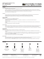
Wire Connector
Qty: 5 pcs + 1 Extra
7EAC112201
Junction Box Screw
Qty: 2 pcs + 1 Extra
7MPF0820C1
#8-32x13/16
Mounting Screw
Qty: 1 Extra
7MPF0309S3
1/8-40x3/8
Nickel Plating
Allen Wrench
Qty: 1 pc
7MPE205001
Allen Screw
Qty: 1 Extra
7MPF0403K1
5/32-32x3/16
Nickel Plating
A1 B1 C1 D1 E1

2Modern Forms retains the right to modify the design of our products at any time as part of the company's continuous improvement program.
modernforms.com
Phone (800) 526.2588
Fax (800) 526.2585
Headquarters/Eastern Distribution Center
44 Harbor Park Drive
Port Washington, NY 11050
Central Distribution Center
1600 Distribution Ct
Lithia Springs, GA 30122
Western Distribution Center
1750 Archibald Avenue
Ontario, CA 91760
PREPARATION
1. Shut o the power at the circuit breaker and remove existing xture, including the crossbar.
2. Carefully unpack your new xture and lay out all the parts on a clear area. Be careful not to lose any small parts necessary for installation.
CONNECTING THE WIRES (Fig. 2)
3. Remove the mounting screws (C1) from the xture.
4. Connect the driver input wires with supply wires as shown in Fig. 2, making sure that all wire connectors (A1) are secured. If your outlet box
has a green or bare copper ground wire, connect the xture’s ground wire to it. Otherwise, connect the xture’s ground wire directly to the
mounting plate using the green screw provided. After wires are connected, tuck them carefully inside the junction box.
*Requires Driver to be recessed within the junction box.
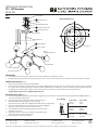
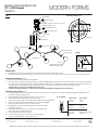
MOUNTING THE FIXTURES (Fig. 1)
5. Secure mounting back plate to the junction box using junction box screws (B1). The side of the mounting plate marked “GND” must face
out. Pull out the driver output wire.
6. Choose the number of down rods suitable of your application.
7. Thread the xture wire through the rods and canopy.
Connect the canopy, down rod and xture body. Make sure all are tightened.
8. Connect the driver output wires with xture wire as shown in Fig. 2,
making sure that all wire connectors ( A1) are secured.
9. Place the xture over the mounting back plate and secure it with
mounting screws (C1).
10. Adjust the connection tubes to your desired angle, fasten it with
Allen screws (E1) using Allen wrench (D1).
11. Thread the glass into the lamp holder.
Ø
4 3/4"
Wire Connector Back Plate Dimensions
Junction Box Screw
Mounting Screw
Allen Wrench
Allen Screw
Glass
(RPL-GLA-53728-01)
Lamp Holder
Canopy
Down Rod
Driver
Mounting Back Plate
Junction Box
Lamp Body
Connection Tube
A1
B1
C1
D1
E1
FIG. 1
INSTALLATION INSTRUCTION
537 - LED Pendant
PD-53728
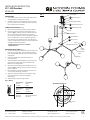
Fixture Wires
Black or
Smooth
Fixture Wires
White or
Ribbed
Fixture Wires
Bare wire
(Ground)
House Wires
Black
(Hot)
House Wires
White
(Neutral)
House Wires
Green or Bare Copper
(Ground)
Fig. 2 Wiring
1 3/4"
1 3/8"

1Modern Forms retains the right to modify the design of our products at any time as part of the company's continuous improvement program.
modernforms.com
Phone (800) 526.2588
Fax (800) 526.2585
Headquarters/Eastern Distribution Center
44 Harbor Park Drive
Port Washington, NY 11050
Central Distribution Center
1600 Distribution Ct
Lithia Springs, GA 30122
Western Distribution Center
1750 Archibald Avenue
Ontario, CA 91760
HARDWARE
WARNING
IMPORTANT: NEVER attempt any work without shutting o the electricity.
- Read all instructions before installing.
- System is intended for installation by a qualied electrician in accordance with the National Electrical Code and local regulations.
- Go to the main fuse box, or circuit breaker. Place the main power switch in the “OFF” position and unscrew the fuse(s) or switch ”OFF”
the circuit breaker switch(es) that control the power to the xture or room that you are working on.
- Place the wall switch in the “OFF” position.
CAUTION
- All parts must be used as indicated in these instructions. Do not substitute any parts, leave parts out, or use any parts that are
worn out or broken. Failure to follow this instruction could invalidate the ETL/CETL listing of this xture.
CAUTION When handling the xture, do not apply pressure to the LEDs. Hold the xture by the base only.
AVERTISSEMENT
IMPORTANT : Coupez l’électricité avant TOUTE manipulation.
- Lisez toutes les instructions avant d’installer.
- Système est destiné à être installé par un électricien qualié en conformité avec le code national de l’électricité et les
règlements locaux.
- Accédez au panneau central de disjoncteurs ou de fusibles de votre demeure et placez l’interrupteur principal en position d’arrêt
(« OFF »).
- Placez l’interrupteur mural en position d’arrêt (« OFF »).
MISE EN GARDE
- Toutes les pièces doivent être utilisées tel qu’il est indiqué dans ces instructions. Ne remplacez pas les pièces, n’en laissez pas de côté
et ne les utilisez pas si elles sont usées ou brisées. Le non-respect de ces instructions peut annuler l’homologation ETL/CETL du
luminaire. MISE EN GARDE Ors de la manipulation de l’appareil, ne pas appliquer de pression à la LED, tenir l’appareil par la seule base.
ADVERTENCIA
IMPORTANTE: NUNCA intente hacer trabajos sin desconectar el suministro eléctrico.
- Lea y comprenda todas las instrucciones e ilustraciones por completo antes de proceder con el ensamblaje e insta lación de esta
lámpara.
- Sistema está disenado para ser instalado por un electricista calicado, de acuerdo con el código eléctrico nacional y las normas locales.
- Diríjase a la caja de fusibles o a la caja del interruptor de circuito principal en su hogar. Coloque el interruptor de ali mentación
principal en la posición “OFF” (APAGADO).
- Coloque el interruptor de la pared en la posición “OFF” (APAGADO).
PRECAUCIÓN
- Todas las piezas deben usarse como lo indican estas instrucciones. No reemplace las piezas, noomita piezas durante la instalación ni
utilice piezas gastadas o rotas. El incumplimiento de esta indicación podría invalidar la calicación
ETL/CETL esta lámpara. PRECAUCIÓN Al manipular el aparato, no aplique presión a los LED, mantenga el aparato en la base sólo.
INSTALLATION INSTRUCTION
537 - LED Pendant
PD-53740
Wire Connector
Qty: 5 pcs + 1 Extra
7EAC112201
Junction Box Screw
Qty: 2 pcs + 1 Extra
7MPF0820C1
#8-32x13/16
Mounting Screw
Qty: 1 Extra
7MPF0309S3
1/8-40x3/8
Nickel Plating
Allen Wrench
Qty: 1 pc
7MPE205001
Allen Screw
Qty: 1 Extra
7MPF0403K1
5/32-32x3/16
Nickel Plating
A1 B1 C1 D1 E1

2Modern Forms retains the right to modify the design of our products at any time as part of the company's continuous improvement program.
modernforms.com
Phone (800) 526.2588
Fax (800) 526.2585
Headquarters/Eastern Distribution Center
44 Harbor Park Drive
Port Washington, NY 11050
Central Distribution Center
1600 Distribution Ct
Lithia Springs, GA 30122
Western Distribution Center
1750 Archibald Avenue
Ontario, CA 91760
PREPARATION
1. Shut o the power at the circuit breaker and remove
existing xture, including the crossbar.
2. Carefully unpack your new xture and lay out all the
parts on a clear area. Be careful not to lose any small
parts necessary for installation.
CONNECTING THE WIRES (Fig. 2)
3. Remove the mounting screws (C1) from the xture.
4. Connect the driver input wires with supply wires as
shown in Fig. 2, making sure that all wire connectors
(A1) are secured. If your outlet box has a green or
bare copper ground wire, connect the xture’s ground
wire to it. Otherwise, connect the xture’s ground
wire directly to the mounting plate using the green
screw provided. After wires are connected, tuck them
carefully inside the junction box.
* Requires Driver to be recessed within
the junction box.
MOUNTING THE FIXTURES (Fig. 1)
5. Secure mounting back plate to the junction box using
junction box screws (B1). The side of the mounting
plate marked “GND” must face out. Pull out the driver
output wire.
6. Choose the number of down rods suitable of
your application.
7. Thread the xture wire through the rods and canopy.
Connect the canopy, down rod and xture body.
Make sure all are tightened.
8. Connect the driver output wires with xture wire as
shown in Fig. 2, making sure that all wire connectors
(A1) are secured.
9. Place the xture over the mounting back plate and
secure it with mounting screws (C1).
10. Adjust the connection tubes to your desired angle,
fasten it with Allen screws (E1) using Allen
wrench (D1).
11. Thread the glass into the lamp holder.
Wire Connector
Junction Box Screw
Mounting Screw
Allen Wrench
Allen Screw
Lamp
Holder
Connection
Tube
Lamp Body
Glass
(RPL-GLA-53728-01)
Canopy
Down Rod
Junction Box
Driver
Mounting Back Plate
A1
B1
C1
D1
E1
FIG. 1
Fixture Wires
Black or
Smooth
Fixture Wires
White or
Ribbed
Fixture Wires
Bare wire
(Ground)
House Wires
Black
(Hot)
House Wires
White
(Neutral)
House Wires
Green or Bare Copper
(Ground)
Fig. 2 Wiring
INSTALLATION INSTRUCTION
537 - LED Pendant
PD-53740
Ø
4 3/4"
Back Plate Dimensions
1 3/4"
1 3/8"

INSTALLATION INSTRUCTION
537 - LED Pendant
PD-53751
CAUTION: TO PREVENT ELECTRICAL SHOCK, ENSURE ELECTRICITY HAS BEEN TURNED OFF AT THE CIRCUIT BREAKER
BEFORE BEGINNING.
‐ Read all instructions before installing.
‐ System is intended for installation by a licensed electrician in accordance with the National Electrical Code (NEC) and local
regulations.
‐ When handling the fixture, do not apply pressure to the LEDs. Hold the fixture by the base only.
‐ Retain installation instructions for future maintenance reference.
WARNING: All parts must be used as indicated in these instructions. This product is designed for use only with the supplied parts
and/or accessories designated for use by Modern Forms. Substitution of parts or accessories not designated for use with this product
by Modern Forms could result in personal injury or property damage, and will void the warranty. Contact an authorized dealer or the
manufacturer if any parts are damaged or missing.
MAINTENANCENOTE:Coastal conditions may cause mineral and residue build-up on the fixture. We recommend that customers in
coastal areas clean all external surfaces of the fixture once every two weeks with a wet cloth.
MISE EN GARDE: Pour éviter tout choc électrique, assurez-vous que le disjoncteur soit mis hors tension avant de
commencer.
‐ Lisez toutes les instructions avant l’installation.
‐ Le système doit être installé par un électricien licensié conformément au code national de l’électricité (NEC), et également
aux règlements locaux.
‐ Lors de la manipulation du luminaire, n’appuyez pas sur les LED. Tenez-le uniquement par la base.
ATTENTION: Toutes les pièces doivent être utilisées comme indiqué dans ces instructions. Ce produit est conçu pour être utilisé
seulement avec les pièces et/ou accessoires fournis pour être utilisés avec les produits Modern Forms. Remplacer des pièces ou
accessoires non conçus pour ce produit Modern Forms pourrait causer des dommages corporels ou matériels et pourrait également
causer l’annulation de la garantie. Veuillez contacter un revendeur autorisé ou le fabricant si des pièces manquent ou sont
endommagées.
NOTED’ENTRETIEN:Les conditions côtières peut causer une accumulation de minéraux et de résidue sur le luminaire. Nous
recommendons aux clients qui resident dans les zones côtières de nettoyer toutes les surfaces externes du luminaire une fois toutes
les deux semaines avec un chiffon humide.
HAR
DWARE
Modern Forms retains the right to modify the design of our products at any time as part of the company's continuous improvement program. Nov. 2019 1
Modernforms.com Headquarters/Eastern Distribution Center Central Distribution Center Western Distribution Center
Phone (866) 810.6615 44 Harbor Park Drive 1600 Distribution Ct 1750 Archibald Ave
Fax (800) 526.2585 Port Washington, NY 11050 Lithia Springs, GA 30122 Ontario, CA 91761
Wire Connector Junction Box Screw Mounting Screw Allen Wrench Allen Screw
Qty: 5 pcs + 1 Extra Qty: 2 pcs + 1 Extra Qty: 1 Extra Qty: 1 pc Qty: 1 Extra
A B C D E

PREPARATION
1. Shut o the power at the circuit breaker and remove existing xture, including the crossbar.
2. Carefully unpack your new xture and lay out all the parts on a clear area. Be careful not to lose any small parts necessary for installation.
CONNECTING THE WIRES (Fig. 2)
3. Remove the mounting screws (C) from the xture.
4. Connect the driver input wires with supply wires as shown in Fig. 2, making sure that all wire connectors (A) are secured. If your outlet box
has a green or bare copper ground wire, connect the xture’s ground wire to it. Otherwise, connect the xture’s ground wire directly to the
mounting plate using the green screw provided. After wires are connected, tuck them carefully inside the junction box.
*Requires Driver to be recessed within the junction box.
The hole mounting extensions on the driver are trimmable/foldable for tighter junction box fitment.
MOUNTING THE FIXTURES (Fig. 1)
5. Secure mounting back plate to the junction box using junction box screws (B). The side of the mounting plate marked “GND” must face
out. Pull out the driver output wire.
Fig. 2 Wiring
Fixture Wires House Wires
Black or Black
Smooth (Hot)
Fixture Wires House Wires
White or White
Ribbed (Neutral)
Fixture Wires House Wires
Bare wire Green or Bare Copper
(Ground) (Ground)
6. Choose the number of down rods suitable of your application.
7. Thread the xture wire through the rods and canopy.
Connect the canopy, down rod and xture body. Make sure all are tightened.
8. Connect the driver output wires with xture wire as shown in Fig. 2,
making sure that all wire connectors ( A) are secured.
9. Place the xture over the mounting back plate and secure it with
mounting screws (C).
10. Adjust the connection tubes to your desired angle, fasten it with
Allen screws (E) using Allen wrench (D).
11. Thread the glass into the lamp holder.
FIG. 1
Ø
4 3/4"
Back Plate Dimensions
1 3/4"
1 3/8"
E
D
C
B
A
Junction Box
Wire Connector
Driver
2 3/4” to 3 3/8"L x 1 1/4” W x 1 1/8” H
Mounting Back Plate
Junction Box Screw
Mounting Screw
Canopy
Down Rod
Swivel
Allen Wrench
Allen Screw
Connection Tube
Lamp Holder
Glass
(RPL-GLA-53728-01)
(RPL-GLA-53728-02)
Lamp Body
12. For slope ceiling application, rotate swivel at the top of the
stem to ensure luminaries is aiming down (Fig. 3).
Fig.3
Turn to down
Modern Forms retains the right to modify the design of our products at any time as part of the company's continuous improvement program. Nov. 2019 2
Modernforms.com Headquarters/Eastern Distribution Center Central Distribution Center Western Distribution Center
Phone (866) 810.6615 44 Harbor Park Drive 1600 Distribution Ct 1750 Archibald Ave
Fax (800) 526.2585 Port Washington, NY 11050 Lithia Springs, GA 30122 Ontario, CA 91761
INSTALLATION INSTRUCTION
537 - LED Pendant
PD-53751
-
 1
1
-
 2
2
-
 3
3
-
 4
4
-
 5
5
-
 6
6


Modern Forms PD-53728 Catalyst Mode d'emploi
- Taper
- Mode d'emploi
dans d''autres langues
Documents connexes
-
Modern Forms PD-94322 Echelon Mode d'emploi
-
-
-
-
-
-
-
-
-
Autres documents
-
WAC Lighting WS-90636 Guide d'installation
-
-
-
-
-
-
-