Acson ACK010CW Installation Instructions Manual
- Catégorie
- Climatiseurs split-system
- Taper
- Installation Instructions Manual

CEILING CASSETTE
CHILLED WATER FAN COIL UNIT
(B & C SERIES)
Model: IM-CKBCW-0503-ACSON
CHILLED WATER
INSTALLATION MANUAL


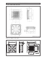
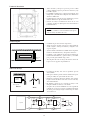
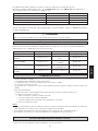
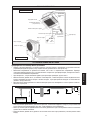
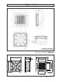
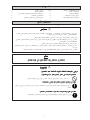
OUTLINE AND DIMENSIONS
Indoor Unit : CK15BW / 20BW / 25BW / 30BW
i
Indoor Unit : CK10CW / 15CW / 20CW
All dimensions are in mm.
All dimensions are in mm.
570
570
295
275
20
640
408
640
408
364
364

ii
! Осторожно
Острые края и поверхности змеевиков являются
потенциальными местами нанесения травм.
Остерегайтесь контакта с этими местами.
! Cuidado
Los Bordes afilados y la superficie del serpentín pueden producir lesiones.
Evite tocarlos.
! Cautela
Per preservarsi da eventuali ferite, evitare di toccare gli spigoli afilati e la
superficie dei serpentini.
! Vorsicht
Scharfe Kanten und Wärmetauscherflächen stellen eine Gefahrenquelle dar.
Jeglicher Kontakt mit diesen Stellen ist zu vermeiden.
! Avertissement
Les bords coupants et les surfaces du refroidisseur tuulaire présentent
un risque de blessure. Mieux vaut éviter le contact avec ces endroits.
! Caution
Sharp edges and coil surfaces are potential locations which may cause
injury hazards. Avoid from being in contact with these places.
This product is subjected to Waste of Electrical and Electronic Equipment Regulations (WEE
E
Regulations). The waste product shall be separately collected by specific collection and treatment centre
.
P
lease refer to local authorithy for these centres. This is only applicable to European Union countries
.
Ce produit est soumis
à
la r
à
é
r
r
é
é
é
lectriques e
t
é
é
é
ê
é
é
é
é
é
é
é
é
é
î
î
tre ces centres. Ceci
îî
est uniquement applicable aux pays de l'Union Euro
p
é
enne
.
Questo prodotto
è
soggetto alle disposizioni RAEE (Rifiuti di apparecchiature elettriche ed elettroniche)
.
à
à
locali. Questa disposizione
à
è
valida solamente i paes
i
d
el
l
’
U.
E
.
é
ctrico y Electr
ó
n
ico en materia d
e
ñ
ñ
á
í
fico
íí
de colecc
i
ó
solamente aplicable a los p
a
í
ses de la
U
n
i
ó
n
Europea
.
Dieses Produkt unterliegt den Bestimmungen zur Entsorgung von elektrischen und elektronische
n
G
er
ä
ä
ä
tes
ää
ü
ü
ll bei Ihrer
ö
ü
ö
ä
ndiges Abfall-Amt. Dieser
ää
Hinweis gilt nur f
ü
f
f
rL
ä
ischen Union
.
П
р
оцес
с
у
тилизаци
и
д
анног
о
прод
у
кт
а
рег
у
лир
у
етс
я
п
р
авилам
и
п
о
у
тилизаци
и
отхо
д
о
в
и
(WEEE Re
g
ulations).
и
,
.
Э
т
и
п
р
авил
а
Ев
р
опейског
о
.
NOTICE

1-1
English
This manual provides the procedures of installation to ensure a safe and good standard of operation for the fan
coil unit.
Special adjustment may be necessary to suit local requirements.
Before using your air conditioner, please read this instruction manual carefully and keep it for future reference.
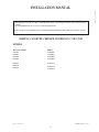
INSTALLATION MANUAL
CEILING CASSETTE CHILLED WATER FAN COIL UNIT
MODEL
Reference Model Model
ACK015BW
ACK020BW
ACK025BW
ACK030BW
ACK010CW
ACK015CW
ACK020CW
CK15BW
CK20BW
CK25BW
CK30BW
CK10CW
CK15CW
CK20CW
Part No.: A08019025516
IM-CKBCW-0503 (1)-Acson

1-2
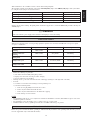
CONTENTS
- Outline And Dimensions page i – ii
- Safety Precautions page 2
- Installation Diagram page 3
- Installation of Indoor Unit page 3
- Electrical Wiring Connection page 6
SAFETY PRECAUTIONS
Before installing the air conditioner unit, please read the following safety precautions carefully.
! Caution
Please take note of the following important points when installing.
• Do not install the unit where leakage of flammable gas may occur.
If water leaks and accumulates around the unit, it may cause fire ignition.
• Ensure that the drainage piping is connected properly.
If the drainage piping is not connected properly, it may cause water leakage which will dampen the
furniture.
• Ensure that the units panel is closed after service or installation.
Unsecured panels will cause the unit to operate noisily.
- Indicator Lights page 9
- Overall Checking page 9
- Auto Random Re-Start Function page 9
- Service and Maintenance page 10
- Troubleshooting page 10
IMPORTANT
DO NOT INSTALL OR USE THE FAN COIL UNIT IN A LAUNDRY ROOM.
! Warning
• Installation and maintenance should be performed by qualified persons who are familiar with local code and
regulation, and experienced with this type of appliance.
• All field wiring must be installed in accordance with the national wiring regulation.
• Ensure that the rated voltage of the unit corresponds to that of the name plate before commencing wiring work
according to the wiring diagram.
• The unit must be GROUNDED to prevent possible hazard due to insulation failure.
• All electrical wiring must not touch the refrigerant piping or any moving parts of the fan motors.
• Confirm that the unit has been switched OFF before installing or servicing the unit.

1-3
English
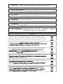
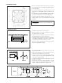
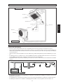
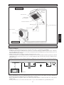
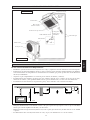
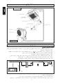
INSTALLATION DIAGRAM
Drain Hose
Front Panel
Air Filter
(behind the grille)
Air Discharge Louver
IR Receiver
LED Light
Water Piping
Air Intake
Air Discharge Nozzle
Air Intake
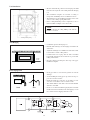
Preliminary Site Survey
• Electrical supply and installation is to conform to local authority's (e.g. National Electrical Board) codes and regulations.
• Voltage supply fluctuation must not exceed
+
10% of rated voltage. Electricity supply lines must be independent of welding
transformers which can cause high supply fluctuation.
• Ensure that the location is convenient for wiring, piping and drainage.
• The indoor unit must be installed in such that is free from any obstacles in path of cool air discharge and warm air return,
and must allow spreading of air throughout the room (near the center of the room).
• Must be provide clearance for the indoor unit from the wall and obstacles as shown in the figure.
• The installation place must be strong enough to support a load 4 times the indoor unit weight to avoid amplifying noise and
vibration.
• The installation place (handing ceiling surface) must be assuring levelness and the height in the ceiling is 350 mm or more.
• The indoor unit must be away from heat and steam sources (avoid installing it near an entrance).
INSTALLATION OF INDOOR UNIT
Max. 0.3 m
Min. 0.5 m
Min. 0.5 m
Min. 0.5 m
Min. 1.0 m
Max. 3.0 m
Floor
Obstacle
Beam
Outdoor Unit
Indoor Unit
Wireless
Remote Control
or
Wired Remote Control
Netware - 2
or
SLM - 3
Air Intake Grille

1-4
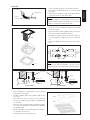
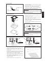
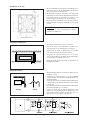
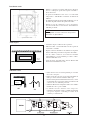
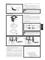
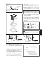
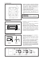
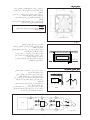
Unit Installation
• Measure and mark the position for the hanging rod. Drill
the hole for the angle nut on the ceiling and fix the hanging
rod.
• The installation template is extended according to
temperature & humidity. Check on dimensions in use.
• The dimensions of the installation template are the same
as those of the ceiling opening dimensions.
• Before ceiling laminating work is completed, be sure to
fit the installation template to the indoor unit.
NOTE
Be sure to discuss the ceiling drilling work with the
installers concerned.
Ceiling board opening
Drain Piping Work
• Drain pipe must be in downward gradient for smooth
drainage.
• Avoid installing the drain pipe in up and down slope to
prevent reversed water flow.
• During the drain pipe connection, be careful not to exert
extra force on the drain connector at indoor unit.
• The outside diameter of the drain connection at the flexible
drain hose is 20 mm.
• Be sure to execute heat insulation (polyethylene foam with
thickness more than 8.0 mm) on the drain piping to avoid
the condensed water dripping inside the room.
Indoor Unit
Pipe Clamp
Good
Bad
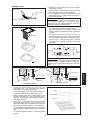
Unit Hanging
• Confirm the pitch of the hanging rod.
• Hold the unit and hang it on the hanging rod with the nut
and washer.
• Adjust the unit height to 35.0 mm between the indoor unit
bottom surface and the ceiling surface.
• Confirm with a level gauge that the unit is installed
horizontally and tighten the nut and bolt to prevent unit
falling and vibration.
• Open the ceiling board along the outer edge of the paper
installation template.
Ceiling
Board
35.0 mm
Indoor Unit

1-5
English
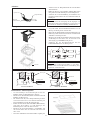
Drain Test
NOTE
This indoor unit uses a drain pump for condensed water
drainage. Install the unit horizontally to prevent water
leakage or condensation around the air outlet.
Main Drain Pipe
Feed Water
Flexible
Drain Hose
• Connect the main drain pipe to the flexible drain hose.
• Feed water from flexible drain hose to check the piping
for leakage.
• When the test is completed, connect the flexible drain hose
to the drain connector on the indoor unit.
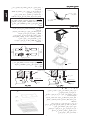
NOTE
Install the front frame panel firmly to prevent cool air
leakage which will cause condensation and water dripping.
OPEN
• Be sure to remove the installation template before install-
ing the front panel.
• Open the air intake grille by pulling back the catchers and
removing it together with filter from panel.
• Install the front frame panel onto the indoor unit by 4
screws and tighten it completely to prevent cool air leak-
age.
• Connect the LED wire and air swing wire to the indoor
unit.
Panel Installation
Indoor unit
cool
air
ceiling board
Panel
air leak
cool
air
air leak
ceiling board
Panel
Good Installation
Bad Installation
From
Front
Panel
LED Wire
Air Swing Wire
From
Control
Box
Screw
Air intake grille installation
• Before installing the air intake grille, be sure to fix the
ionizer filter to the air filter.
• Install the air intake grille together with the air filter to the
front panel.
• The grille can be fit in any direction, when selecting
direction, the ceiling design and grille operability should
be considered.
• If the unit comes with ionizer filter (optional item), make
sure to fix the ionizer filter to the air filter before installing
the air intake grille.
• Fix the ionizer filter to the air filter with the black side on
top and white side at bottom.
• Carefully clip on the ionizer filter frame.
Frame
Ionizer
Filter

1-6
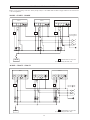
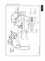
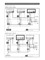
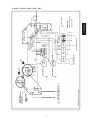
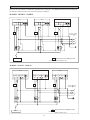
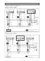
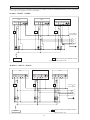
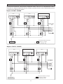
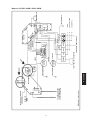
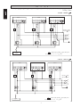
ELECTRICAL WIRING CONNECTION
This is a proposed wiring connection. It may change subject to the chiller unit and must comply with the local and national
code and regulations.
MODEL : CK15BW - CK30BW
3WV3WV
X1 X2 X3
3WV
R
COMPCOMPL/L1
N/L2 N/L2
COMP
S
T
N
CHILLER
FCU 1 FCU 2 FCU 3
200-240V/1 /50Hz
208-230V/1 /60Hz
3WV
Solenoid Valve for 3 way valve
Relay (220-240V, 10A)
X1, X2, X3
L/L1
N/L2 N/L2
L/L1
N/L2 N/L2
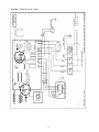
MODEL : CK10CW - CK20CW
X1 X2
X3
3WV 3WV 3WV
R
L/L1 N/L2 N/L2COMP
S
T
N
CHILLER
FCU 1
L/L1 N/L2 N/L2COMP
FCU 3
L/L1 N/L2 N/L2COMP
FCU 2
200-240V/1 /50Hz
208-230V/1 /60Hz
3WV
Solenoid Valve for 3 way valve
Relay (220-240V, 10A)
X1, X2, X3

1-7
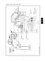
English
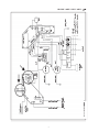
L/L1 N/L2 N/L2
COMP
SOLENOID VALVE
PART NO : 08 02 4 063847
TO CHILLER
L 1PHASE
N 200 / 240VAC 50Hz
E 208 / 230VAC 60Hz OR
GREEN/YELLOW
GREEN/YELLOW
BLUE
WHITE
RED
RED
BLUE
BLACK
POWER
BOARD
BROWN (FM)
ORANGE (FL)
YELLOW (FH)
BLUE
TRANSFORMER
LIVE
LO MED
HI
WTP AG
VALVE
SWING
MOTOR
WATER
PUMP
LEVEL
SWITCH
GREEN/YELLOW
TO WIRED OR WIRELESS
CONTROLLER
GREEN/YELLOW
JVLV
T.FULL
MAIN BOARD
I/D COIL SENSOR
THERMISTOR
WIRED CONTROLLER
WIRELESS CONTROLLER
VALVE
HEAT
BLAC
BLACK
GREEN/
YELLOW
FAN MOTOR
AC LC
MLC
WHITE
RED
N2
N1
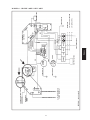
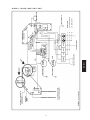
MODEL : CK15BW / 20BW / 25BW / 30BW

1-8
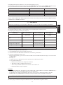
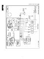
L 1PHASE
N 220 / 240VAC 50Hz OR
E 208 / 230VAC 60Hz
L/L1 N/L2 N/L2
COMP
BLUE
RETURN AIR SENSOR
INDOOR COIL SENSOR
ROOM
ID
OD
HEAT
JH
CN3
JVLV
CN6
LOW
N2
MED
HIGH
AS
VALVE
WTP
N1
L1
TRANSFORMER
CN4
FLOAT SWITCH
WIRED OR
WIRELESS
REMOTE
CONTROLLER
YELLOW FH
BROWN FM
ORANGE FL
BLACK
WHITE
RED
AC IC
MC
FAN MOTOR
PURPLE
RED
BLACK
(TO OUTDOOR UNIT)
BLUE
BLUE
DP
AS
G/Y
G/Y
BLACK
RED
(POWER SUPPLY FROM INDOOR UNIT)
PART NO: 08 02 4 066429
MODEL : CK10CW / 15CW / 20CW

1-9
English
OVERALL CHECKING
• Ensure the following, in particular:-
1) The unit is mounted solidly and rigid in position.
2) Piping and connections are leak proof after charging.
3) Proper wiring has been installed.
• Drainage check – pour some water into left side of drain pipe (drainage is at the right side of the unit).
• Test run:
1) Conduct a test run after water drainage test and gas leakage test.
2) Check the following items:-
a. Is the electric plug firmly inserted into the socket?
b. Is there any abnormal sound from the unit?
c. Is there any abnormal vibration on the unit itself or piping?
d. Is the drainage of water smooth?
NOTE
• The installation guide above covers only the fan coil unit. For installation of outdoor (mini chiller etc) please refer to the
installation guide for such unit.
• The installation of fan coil unit may vary according to the type of outdoor unit.
• Installation must be done by qualified personnel who are familiar with this type of product.
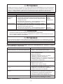
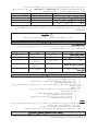
INDICATOR LIGHTS
Remote Control
When there is infrared remote control operating signal, the signal receiver on indoor unit will made a <beep> for signal
acceptance confirmation.
Other LED
Fan blinks
Sleep blinks
Cool & Fan blinks
Cool & Dry blinks
Cool blinks
Seven Segments
E1 blinking
E2 blinking
E6 blinking
E4 blinking
E5 blinking
Operation LED
blinks 4 times
blinks 4 times
blinks 2 times
blinks 3 times
blinks 1 time
Faulty Indication
Room Sensor
missing
Indoor Coil Sensor
missing
Pump fault
Pipe Water
Temperature poor
Pipe Water
Temperature fault
If there is a power cut when the unit is operating, it will automatically resume the same operating mode when the power is
restored. (Applicable only to units with this feature)
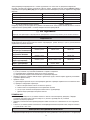
AUTO RANDOM RE-START FUNCTION
Wire termination to the controller board is as shown in the wiring diagrams.
The standard controller board (W1V3) comes with a VALVE (JVLV) jumper and a HEAT (OD) jumper. The system must
be configured as the jumper selection listed below:
√
Jumper Remained
×
Jumper Removed
Example: If the unit is running “Heatpump Mode & Valveless Application”, remain the HEAT jumper while removing the
VALVE jumper.
HEAT Jumper VALVE Jumper
Cooling Mode & Valve Application ×
√
Cooling Mode & Valveless Application ××
Heatpump Mode & Valve Application √√
Heatpump Mode & Valveless Application √ ×
! Caution
Disconnect the live power supply to the unit before attempting to connect the wiring.

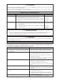
1-10
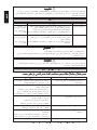
Causes / Action
- Protection against frequent starting. Wait for 3 to 4
minutes for the compressor to start operating.
- Power failure, or the fuse need to be replaced.
- The power plug is disconnected.
- It is possible that your delay timer has been set incorrectly.
- If the fault persist after all these verifications, please
contact the unit installer.
- The air filter is dirty.
- The doors or windows are open.
- The air suction and discharge are clogged.
- The regulated temperature is not high enough.
- Odors may be caused by cigarettes, smoke particles,
perfume etc. which might have adhered onto the coil.
- This is caused by air humidity after an extended long
period of operation.
- The set temperature is too low, increase the temperature
setting and operate the unit at high fan speed.
- Switch off unit and call dealer.
Fault
1. The compressor does not start operate after 3 minutes
from starting the air conditioner unit.
2. The fan coil unit does not operate.
3. The airflow is too low.
4. Discharge airflow has bad odor.
5. Condensation on the front air grille of the indoor unit.
6. Water flowing out from the fan coil unit.
When any malfunction of the air conditioner unit is noted, immediately switch off the power supply to the
unit. Check the following fault conditions and causes for some simple troubleshooting tips.
TROUBLESHOOTING
If the fault persists, please call your local dealer / serviceman.
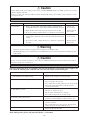
SERVICE AND MAINTENANCE
Indoor Air Filter 1. Remove any dust adhere on the filter by using a vacuum cleaner or
wash in lukewarm water (below 40
o
C) with neutral cleaning detergent.
2. Rinse the filter well and dry before placing it back onto the unit.
3. Do not use gasoline, volatile substances or chemical to clean the filter.
Indoor Unit 1. Clean any dirt or dust on the grille or panel by wiping it off with soft
cloth soaked in lukewarm water (below 40
o
C) with neutral detergent
solution.
2. Do not use gasoline, volatile substances or chemical to clean the in-
door unit.
At least once
every 2 weeks.
More frequently
if necessary.
At least once
every 2 weeks.
More frequently
if necessary.
Service Parts Maintenance Procedures Period
! Warning
• Disconnect from the main power supply before servicing the air conditioner unit.
• DO NOT pull out the power cord when the power is ON. This may cause serious electrical shocks which may result
in fire hazards.
! Caution
Do not operate any heating apparatus too close to the air conditioner unit. This may cause the plastic panel to melt or
deform as a result of the excessive heat.
! Caution
Before turning off the power supply, set the remote controller's ON/OFF switch to the “OFF” position to prevent the
nuisance tripping of the unit.
If this is not done, the unit's fans will start turning automatically when power resumes, posing a hazard to service
personnel or the user.

2-1
Français
Ce manuel fournit les procédures d’installation pour assurer le bon fonctionnement et la sécurite de cet
appareil.
Des ajustements peuvent être nécéssaires pour suivre les réglementations locales.
Avant d’installer et de faire fonctionner le climatiseur, lisez attentivement ce manuel et conservez le.
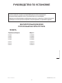
MANUEL D’INSTALLATION
CASSETTE De PLAFOND A REFROIDI L’UNITÉ D’ENROULEMENT
De VENTILATEUR De l’EAU
MODÈLE
Modèle de référence Modèle
CK15BW
CK20BW
CK25BW
CK30BW
CK10CW
CK15CW
CK20CW
Part No.: A08019025516
ACK015BW
ACK020BW
ACK025BW
ACK030BW
ACK010CW
ACK015CW
ACK020CW
IM-CKBCW-0503 (1)-Acson

2-2
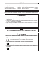
! Avertissement
Vérifier les points suivant au cours de l’installation.
• Ne pas installer l’appareil où il peut se produire des fuites de gaz inflammable.
si l’eau fuit et s’accumule autour de l’unité, elle peut causer l’allumage du feu.
• S’assurer que le tuyau d’évacuation du condensat est correctement branché.
Si le tuyau d’évacuation n’est pas correctement branché, les éventuelles fuites d’eau risquent de mouiller
le mobilier.
• S’assurer que le panneau supérieur de l’appareil est remis en place après l’installation ou l’entretien.
Avec un panneau mal fixé l’appareil va fonctionner bruyamment.
SOMMAIRE
- Schéma et dimensions page i – ii
- Précautions de sécurité page 2
- Diagramme d’installation page 3
- Installation de l’unité intérieure page 3
- Raccordement électrique page 6
PRÉCAUTIONS DE SÉCURITÉ
Avant de faire fonctionner l’appreil, veuillez bien lire précautions de sécurite suivantes.
- Voyants indicateurs page 9
- Vérifications générales page 9
- Fonction de redemarrage au hasard automatique page 9
- Maintenance periodique du climatiseur page 10
- Analyse des causes de dysfonctionnement
de climatiseur page 10
! Attention
• L’installation et la maintenance doivent être exécutées par une personne qualifiée qui est familiarisée avec les lois
et réglementations en vigueur, et aussi expérimentée dans ce type d’équipements.
• Tous les câblages doivent répondre aux réglementations électriques nationales.
• Avant de commencer le raccordement suivant le schéma électrique, s’assurer que la tension nominale de l’appareil
corresponde bien à celle indiquée sur la plaque signalétique.
• L’unité doit être raccordée à la TERRE puor prévenir tous les risques possibles dûes à un défaut d’isolation.
• Aucun câble électrique ne doit toucher la tuyauterie du réfrigérant, le compresseur ou les pièces mobiles des
moteurs de ventilation.
• Avant l’installation ou l’entretien du climatiseur, s’assurer que l’appareil est éteint (OFF).
IMPORTANT
NE PAS INSTALLER OU UTILISER LE CLIMATISEUR DANS UNE BUANDERIE.

2-3
Français
DIAGRAMME D’INSTALLATION
Etude Preliminaire Du Site
• L’alimentation électrique et l’installation doivent être conformes à la réglementation locale (p.ex. agréé EDF).
• Les fluctuations de tension du réseau doivent rester dans la limite de ±10% de la tension nominale. Le climatiseur ne doit
pas partager les lignes d’alimentation électrique avec des transformateurs de soudage, qui risquent de causer d’importantes
fluctuations.
• Assurez-vous que l’emplacement est pratique pour les branchements, la tuyauterie et l’évacuation.
• L’unité intérieure doit être installée de façon à ce qu’aucun obstacle ne bloque le refoulement d’air froid et l’entrée d’air
chaud et de façon à ce que l’air puisse se répandre dans la pièce (près du centre de la pièce).
• Un espace doit être ménagé entre l’unité intérieure et le mur et les obstacles comme le montre la figure.
• L’endroit d’installation doit être assez fort pour supporter une charge quatre fois supérieure au poids de l’unité intérieure
pour éviter l’amplification du bruit et des vibrations.
• L’endroit d’installation (surface du plafond) doit être plane et la hauteur du plafond d’au moins 350 mm.
• L’unité intérieure doit être à l’écart de sources de chaleur ou de vapeur (évitez de l’installer près d’une entrée).
INSTALLATION DE L’UNITÉ INTÉRIEURE
Max. 0,3 m
Min. 0,5 m
Min. 0,5 m
Min. 0,5 m
Min. 1,0 m
Max. 3,0 m
Sol
Obstacle
Poutre
Tuyau d’evacuation
Grille avant
Filtre à air
(derrière la grille)
Conduit de ventilation
Récepteur à
infrarouge
Voyant
lumineux
DEL
Grilles de reprise d’air
Canalisation D’eau
Reprise Air
Refoulement d’air
Reprise Air
Unité Extérieure
Unité Intérieure
Netware - 2
ou
SLM -3
Télécommande
ou
Télécommande sans fil

2-4
Installation de l’unité
Accrochage de l’unité
• Confirmer le pas de la barre de suspension.
• Mainrenez l’unité et accrochez-la à la tringle d’accrochage
à l’aide des écrous et des joints.
• Laissez un espace de 35,0 mm entre la surface inférieure
de l’unité intérieure et la surface du plafond.
• A l’aide d’un indicateur de niveau, assurez-vous que l’unité
est installée horizontalement et serrez l’écrou et le boulon
pour empêcher que l’unité ne tombe et ne vibre.
• Ouvrez le coffrage du plafond le long du bord extérieur
du gabarit d’installation en papier.
• Mesurez et marquez l’emplacement de la tige suspendue.
Percez un trou pour l’écrou d’angle dans le plafond et fixez
la tige suspendue).
• Le gabarit d’installation est agrandi en fonction de la
température et de l’humidité. Vérifier les dimensions en
usage.
• Les dimensions du gabarit d’installation sont les mêmes
que celles des dimensions de l’ouverture du plafond.
• Lorsque le travail de stratification du plafond n’est pas
terminé, veillez à fixer le gabarit d’installation sur l’unité
intérieure.
REMARQUE
Assurez-vous de discuter le perçage du plafond avec
les installateurs.
Ouverture de coffrage du plafond
Coffrage
de plafond
Tuyauterie d’évacuation
• Le tuyau d’évacuation doit être incliné vers le bas pour
une évacuation facile.
• Evitez de positionner le tuyau vers le haut puis vers le bas
afin d’éviter que le flux d’eau ne soit inversé.
• Lorsque vous connectez les tuyaux d’évacuation, assurez-
vous de ne pas exercer de pression supplémentaire sur le
connecteur de l’unité intérieure.
• Le diamètre extérieur du connecteur de drainage au tuyau
flexible est de 20 mm.
• Assurez-vous d’isoler le tuyau d’évacuation contre la
chaleur (mousse en polyéthylène de plus de 8,0 mm
d’épaisseur) afin d’éviter que l’eau condensée ne.
Unité
Intérieure
Collier pour tuyaux
Bon
Mauvais
Unité Intérieure
35,0 mm

2-5
Français
Test d’évacuation
REMARQUE
Cette unité intérieure utilise une pompe d'evacuation pour
l'evacuation de l'eau condensee. Installez l'unite
horizontalement pour eviter que l'eau ne fuie ou ne se
condense autour du deflecteur
Tuyau d’évacuation
principal
Envoyez l’eau
Tuyau
d’évacuation
flexible
REMARQUE
Installez le panneau du cadre avant fermement pour éviter
que l’air froid ne s’échappe, que de la condensation ne se
forme et que de l’eau ne goutte.
• Assurez-vous d’ôter le gabarit d’installation avant
d’installer le panneau avant.
• Ouvrez la grille d’aspiration d’air en tirant le dispositif de
prise de griffes et ôtez-la avec le filtre.
• Installez le panneau du cadre avant sur l’unité intérieure à
l’aide de 4 vis et serrez-les complètement pour éviter que
l’air froid ne s’échappe.
• Connecter le fil du voyant LED et le fil de direction d’air
à l’unité intérieure.
Installation du panneau
• Connectez le tuyau d’évacuation principal au tuyau
d’évacuation flexible.
• Envoyez de l’eau dans le tuyau d’évacuation flexible et
vérifiez qu’il n’y a pas de fuite dans la tuyauterie.
• Lorsque le test est terminé, connectez le tuyau flexible au
connecteur d’évacuation sur l’unité intérieure.
Air
froid
Unité Intérieure
Coffrage
de plafond
Fuite d’air
Installation correcte
Installation mauvais
Air
froid
Fuite d’air
Coffrage
de plafond
Avant
Avant
OUVERT
Vis
Du
Panneau
D’avant
Fil de La LED
Fil de Direction D’air
Depuis
la Base
Actuelle
Installation de la grille d’aspiration
• Avant d’installer la grille d’arrivée d’air, assurez-vous que
le filtre à air soit bien fixé à la grille d’arrivée d’air.
• Installez la grille d’aspiration avec le filtre à air sur le
panneau avant.
• La grille peut être installée dans n’importe quelle direction,
lorsque vous choisissez la direction, prenez en compte le
dessin du plafond et l’accessibilité de la grille.
• Dans le cas où l’unité est vendue avec le filtre ioniseur (en
option), veillez à bien fixer le filtre ioniseur au filtre à air
avant d’installer la grille d’arrivée d’air.
• Fixez le filtre ionisant au filtre à air, côté noir au-dessus,
côté blanc au-dessous.
• Attachez soigneusement le cadre du filtre ionisant.
Cadre
Ionisant
Filtre

2-6
RACCORDEMENT ÉLECTRIQUE
Ceci est un raccordement de câblage proposé, il peut changer sujet à l’unité de réfrigérateur et et doit se conformer au code et
aux règlements locaux et nationaux.
MODÈLE: CK15BW - CK30BW
MODÈLE: CK10CW - CK20CW
3WV3WV
X1 X2 X3
3WV
R
COMPCOMPL/L1
N/L2 N/L2
COMP
S
T
N
FCU 1 FCU 2 FCU 3
200-240V/1 /50Hz
208-230V/1 /60Hz
3WV
X1, X2, X3
L/L1
N/L2 N/L2
L/L1
N/L2 N/L2
Valve de solénoïde pour la valve de 3 manières.
Relais (220-240V, 10A)
Refroidisseur
X1 X2
X3
3WV 3WV 3WV
R
L/L1 N/L2 N/L2COMP
S
T
N
FCU 1
L/L1 N/L2 N/L2COMP
FCU 3
L/L1 N/L2 N/L2COMP
FCU 2
200-240V/1 /50Hz
208-230V/1 /60Hz
3WV
X1, X2, X3
Valve de solénoïde pour la valve de 3 manières.
Relais (220-240V, 10A)
Refroidisseur
La page est en cours de chargement...
La page est en cours de chargement...
La page est en cours de chargement...
La page est en cours de chargement...
La page est en cours de chargement...
La page est en cours de chargement...
La page est en cours de chargement...
La page est en cours de chargement...
La page est en cours de chargement...
La page est en cours de chargement...
La page est en cours de chargement...
La page est en cours de chargement...
La page est en cours de chargement...
La page est en cours de chargement...
La page est en cours de chargement...
La page est en cours de chargement...
La page est en cours de chargement...
La page est en cours de chargement...
La page est en cours de chargement...
La page est en cours de chargement...
La page est en cours de chargement...
La page est en cours de chargement...
La page est en cours de chargement...
La page est en cours de chargement...
La page est en cours de chargement...
La page est en cours de chargement...
La page est en cours de chargement...
La page est en cours de chargement...
La page est en cours de chargement...
La page est en cours de chargement...
La page est en cours de chargement...
La page est en cours de chargement...
La page est en cours de chargement...
La page est en cours de chargement...
La page est en cours de chargement...
La page est en cours de chargement...
La page est en cours de chargement...
La page est en cours de chargement...
La page est en cours de chargement...
La page est en cours de chargement...
La page est en cours de chargement...
La page est en cours de chargement...
La page est en cours de chargement...
La page est en cours de chargement...
La page est en cours de chargement...
La page est en cours de chargement...
La page est en cours de chargement...
La page est en cours de chargement...
La page est en cours de chargement...
La page est en cours de chargement...
La page est en cours de chargement...
La page est en cours de chargement...
La page est en cours de chargement...
La page est en cours de chargement...
La page est en cours de chargement...
La page est en cours de chargement...
La page est en cours de chargement...
La page est en cours de chargement...
La page est en cours de chargement...
La page est en cours de chargement...
La page est en cours de chargement...
La page est en cours de chargement...
La page est en cours de chargement...
La page est en cours de chargement...
-
 1
1
-
 2
2
-
 3
3
-
 4
4
-
 5
5
-
 6
6
-
 7
7
-
 8
8
-
 9
9
-
 10
10
-
 11
11
-
 12
12
-
 13
13
-
 14
14
-
 15
15
-
 16
16
-
 17
17
-
 18
18
-
 19
19
-
 20
20
-
 21
21
-
 22
22
-
 23
23
-
 24
24
-
 25
25
-
 26
26
-
 27
27
-
 28
28
-
 29
29
-
 30
30
-
 31
31
-
 32
32
-
 33
33
-
 34
34
-
 35
35
-
 36
36
-
 37
37
-
 38
38
-
 39
39
-
 40
40
-
 41
41
-
 42
42
-
 43
43
-
 44
44
-
 45
45
-
 46
46
-
 47
47
-
 48
48
-
 49
49
-
 50
50
-
 51
51
-
 52
52
-
 53
53
-
 54
54
-
 55
55
-
 56
56
-
 57
57
-
 58
58
-
 59
59
-
 60
60
-
 61
61
-
 62
62
-
 63
63
-
 64
64
-
 65
65
-
 66
66
-
 67
67
-
 68
68
-
 69
69
-
 70
70
-
 71
71
-
 72
72
-
 73
73
-
 74
74
-
 75
75
-
 76
76
-
 77
77
-
 78
78
-
 79
79
-
 80
80
-
 81
81
-
 82
82
-
 83
83
-
 84
84


Acson ACK010CW Installation Instructions Manual
- Catégorie
- Climatiseurs split-system
- Taper
- Installation Instructions Manual
dans d''autres langues
- italiano: Acson ACK010CW
- English: Acson ACK010CW
- español: Acson ACK010CW
- Deutsch: Acson ACK010CW
- русский: Acson ACK010CW