
1184 WIRELESS CARBON
MONOXIDE DETECTOR
Installation Guide
DESCRIPTION
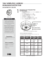
The 1184 is a 3 V battery powered
wireless carbon monoxide (CO)
detector that provides early
warning when the electrochemical
sensing technology measures CO
levels in the air.
The detector has an electrochemical
CO sensor assembly coupled with
an 1100 Series wireless transmitter
and an audible sounder. The
transmitter can send alarm, trouble,
tamper, and low battery condition
messages to the alarm panel.
The detector works well for dicult
wiring locations, for critically
aesthetic applications, or for areas
where hazardous materials exist.
Compatibility
• All DMP 1100 Series Receivers and
Panels.
What is Included?
• 1184 Carbon Monoxide Detector
with DMP wireless transmitter
installed
• 3V lithium Model CR123-FIRE
battery
• Hardware pack
1
PROGRAM THE TRANSMITTER
IN THE PANEL
1. In ZONE INFORMATION, enter the wireless ZONE NO: - and
press CMD.
2. Enter the ZONE NAME and press CMD.
3. Select CO for ZONE TYPE and press CMD.
4. At NEXT ZN?, select NO.
5. Select YES when WIRELESS? displays.
6. Enter the eight-digit SERIAL#:- and press CMD.
7. Enter the SUPRVSN TIME and press CMD.
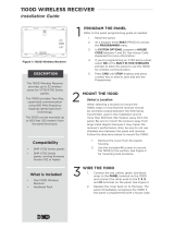
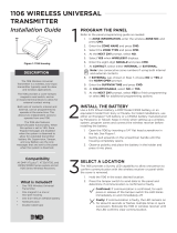
Figure 1: 1184
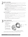
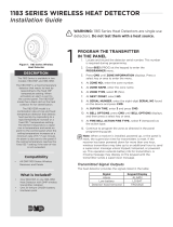
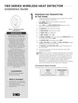
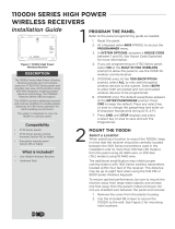
Figure 2: Carbon Monoxide Detector Callouts
1
TEST/HUSH BUTTON
2
GREEN LED
Normal
3
RED LED
Alarm
4
CO ENTRY POINTS
5AUDIBLE SOUNDER
1
2
3
4
5
Detector Annunciation Notifications
The 1184 provides the following transmitter messages, LED
display, and audible annunciations:
MESSAGE
KEYPAD
DISPLAY
RED
LED
GREEN
LED
SOUNDER
Alarm ALARM
Blinks
once
every
second
O Temporal 4
Low
battery
LO BAT
Blinks
once
every 45
seconds
O
Chirps after
7 days
Detector
Head
Removed
TROUBLE
Blinks
once
every 5
seconds
O
One chirp
every
45 seconds
Tamper
TAMPER
(XR150/XR550)
OPEN
(XTL/XT30/XT50)
O On O
Detector
End of Life
TROUBLE
Blinks
once
every 10
seconds
O
One chirp
every
45 seconds
Table 1: Detector Notifications

2 1184 INSTALLATION GUIDE | DIGITAL MONITORING PRODUCTS
MOUNT THE DETECTOR
When setting up a wireless system, it is recommended to program zones and connect the wireless receiver
before installing batteries in the transmitters.
3
Install the transmitter away from large metal objects which impair wireless performance. For the LED Survey
Operation complete the following steps before proceeding:
1. Use a separate 1100 Series Transmitter for the LED Survey Operation such as an 1106 since the 1184
transmitter PCB is not visible.
2. Find the survey button on the 1106 transmitter PCB and the survey LED near the survey button location.
The transmitter PCB Red Survey LED turns on whenever data is sent to the receiver then immediately
turns o when the receiver acknowledgement is received.
3. Press and release the tamper switch to send data to the receiver to confirm operation.
Confirmed: If communication is confirmed, for each press or release of the tamper switch, the LED
blinks immediately on and immediately o.
Faulty: If communication is faulty, the LED remains on for about 8 seconds or flashes multiple times
in quick succession. Relocate the [generic product] or receiver until the LED confirms clear
communication.
4. Test the communication between the control panel and the detector using the panel walk test feature.
See Test the Detector Alarm.
General Location Guidelines
In addition to NFPA 720, use the following location guidelines to optimize performance from the CO detector:
• Install ceiling-mounted detectors at least 12 inches from any wall
• Install wall-mounted detectors at least as high as the light switch and 6 inches below the ceiling.
• Mount the detector on a firm permanent surface
• Locate the detector in environmentally controlled areas where the temperature does not exceed 104° F
(40° C) or drop below 32° F (0° C).
• When mounting to suspended ceiling tile, the tile must be secured with the appropriate fastener to
prevent tile removal
• Install in the vicinity of flame-fueled appliances, but no closer than 10 feet.
• Keep detectors away from vents and the reach of children and pets.
SELECT A LOCATION
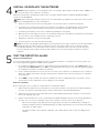
2
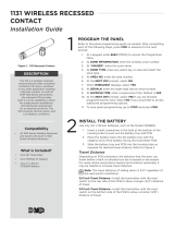
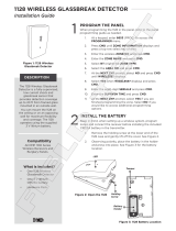
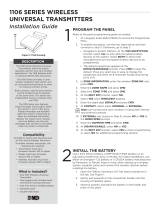
A
Mount the base using the screws
B
Align notch and tab
C
Turn clockwise
A
A
B
B
C
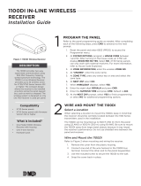
Figure 3: Exploded View of CO Detector
1. Use the two screws
provided to mount the base
in the location previously
surveyed for proper
communication.
2. Use the alignment notch
on the lip of the mounting
base as a guide to align the
detector with the alignment
tabs.
3. Insert the detector into the
mounting base and turn
clockwise approximately 15
degrees to snap into place.
To remove the detector from the mounting base, grasp the detector and turn it counterclockwise
approximately 15 degrees. The detector snaps o of the mounting base. See Figure 3.

1184 INSTALLATION GUIDE | DIGITAL MONITORING PRODUCTS 3
4
INSTALL OR REPLACE THE BATTERIES
Caution: Properly dispose of used batteries. Do not recharge, disassemble, heat above 212°F (100°C), or
incinerate. Risk of fire, explosion, and burns.
Observe polarity when installing the battery. Use only 3.0 V lithium batteries, DMP Model CR123-FIRE or
Panasonic Model CR123A.
Note: When setting up a wireless system, it is recommended to program zones and connect the receiver
before installing batteries in the transmitters.
1. Remove the detector from the mounting base. See the final section of Install the Detector.
2. The battery is located on the inside of the detector. The detector is supplied with a pre-installed
battery. During the initial installation simply remove the battery pull tab to begin operation.
3. If replacing the battery, remove the old battery and dispose of properly.
4. Observing correct polarity, insert the new 3V lithium battery into the battery compartment and replace
the cover. Use only new batteries when replacing old ones.
5. Reattach the detector to the mounting base.
6. Test the detector. See Test the Detector Alarm.
Note: The power cell degrades predictably over its 6-year life. As it ages, a timer runs, and compensation
is applied. When the timer expires, the detector enters end of life trouble. In the end of life trouble,
the red LED will flash once every 10 seconds, and the sounder will chirp every 45 seconds and can’t
be silenced. End of life trouble is latching and unable to be reset. At this time, the detector must be
replaced.
5
TEST THE DETECTOR ALARM
Wireless Communication
The control panel alarm and all auxiliary functions should be verified for a complete test of the system. See
the panel programming guide for additional information.
1. To conduct the Walk Test, reset the control panel. From the keypad, enter the code 8144 (WALK). The
keypad displays WALK TEST. Select STD for Standard Walk Test. Refer to the panel programming guide
for complete information on Walk Test operation.
2. Insert a small screwdriver into the Test hole on the front of the detector to activate the test, sound the
detector’s audible and send a message. Verify that the walk test trip counter increments to indicate a
successful test.
3. Select END to stop the Walk Test. When the Walk Test ends or a 20-minute time-out expires, a final
Sensor Reset occurs. Faulted zones then display on the keypad.
Detector Sensitivity
Before testing, be sure to notify the central station to avoid false alarms.
1. With a small screwdriver, press and hold the recessed Test switch on the detector for approximately 2
seconds. The detector will temporarily sound an alarm and the red LED will illuminate.
2. Within a few seconds the green LED will start to blink rapidly indicating the detector is in functional
test mode awaiting gas entry.
3. Spray a very small amount of Solo
TM
brand C6 canned CO, available at most local security distributors
or online, into one of the 3 small gas entry holes located on the top center of the detector.
Upon successful gas entry and if functioning properly, the detector will alarm by sounding in a
Temporal 4 pattern with the red LED blinking. An alarm signal will be sent to the panel providing
verification of alarm signal.
The alarm condition at the detector will time out in 20 to 60 seconds or when the CO gas has
cleared.

Designed, engineered, and
manufactured in Springfield, MO
using U.S. and global components.
LT-1196 1.03 20115
1184
Specifications
Sensor Life Expectancy Minimum of 3 years,
maximum of 6 years
Battery
Life Expectancy Minimum of 2 years (normal operation)
3 V Lithium CR123-FIRE
Low Battery 2.7 V
Frequency Range 905 - 924 MHz
Dimensions 5.8” x 2.2”
(14.3 cm x 6.1 cm)
Color White
Patents
U.S. Patent no. 7,239,236
Certifications
California State Fire Marshal (CSFM)
FCC Part 15: CCKPC0104
New York City 1100 Series Wireless (FDNY COA #6167)
Industry Canada: 5251A-PC0104
Underwriters Laboratory (UL) Listed
ANSI/UL 2075 Gas and Vapor Detectors and Sensors
INTRUSION • FIRE • ACCESS • NETWORKS
2500 North Partnership Boulevard
Springfield, Missouri 65803-8877
800.641.4282 | DMP.com
FCC INFORMATION
This device complies with Part 15 of the FCC Rules. Operation is subject to the following two conditions:
1. This device may not cause harmful interference, and
2. this device must accept any interference received, including interference that may cause undesired operation.
The antenna used for this transmitter must be installed to provide a separation distance of at least 20 cm (7.874 in.) from all persons. It
must not be located or operated in conjunction with any other antenna or transmitter.
Changes or modifications made by the user and not expressly approved by the party responsible for compliance could void the user’s
authority to operate the equipment.
Note: This equipment has been tested and found to comply with the limits for a Class B digital device, pursuant to part 15 of the
FCC Rules. These limits are designed to provide reasonable protection against harmful interference in a residential installation.
This equipment generates, uses and can radiate radio frequency energy and, if not installed and used in accordance with the
instructions, may cause harmful interference to radio communications. However, there is no guarantee that interference will not
occur in a particular installation. If this equipment does cause harmful interference to radio or television reception, which can be
determined by turning the equipment o and on, the user is encouraged to try to correct the interference by one or more of the
following measures:
1. Reorient or relocate the receiving antenna.
2. Increase the separation between the equipment and receiver.
3. Connect the equipment into an outlet on a circuit dierent from that to which the receiver is connected.
4. Consult the dealer or an experienced radio/TV technician for help.
Note: The 1100 Series wireless system is a two-way supervised wireless design. It is compliant with FCC rules as they pertain to 900
MHz Spread Spectrum devices. In rare instances it has been observed that certain 900 MHz cordless telephones may occasionally
experience a clicking sound on the telephone while in use. If this occurs, it may be resolved by selecting a dierent channel on
the cordless telephone, or replacing the cordless phone with a dierent brand or model of 900 MHz telephone or other cordless
telephone.
INDUSTRY CANADA INFORMATION
This device complies with Industry Canada Licence-exempt RSS standards. Operation is subject to the following two conditions:
1. This device may not cause interference, and
2. this device must accept any interference, including interference that may cause undesired operation of the device.
This system has been evaluated for RF Exposure per RSS-102 and is in compliance with the limits specified by Health Canada Safety
Code 6. The system must be installed at a minimum separation distance from the antenna to a general bystander of 7.87 inches (20 cm)
to maintain compliance with the General Population limits.
Le présent appareil est conforme aux CNR d’Industrie Canada applicables aux appareils radio exempts de licence. L’exploitation est
autorisée aux deux conditions suivantes:
1. l’appareil ne doit pas produire de brouillage, et
2. l’utilisateur de l’appareil doit accepter tout brouillage radioélectrique subi, même si le brouillage est susceptible d’en
compromettre le fonctionnement.
L’exposition aux radiofréquences de ce système a été évaluée selon la norme RSS-102 et est jugée conforme aux limites établies par le
Code de sécurité 6 de Santé Canada. Le système doit être installé à une distance minimale de 7.87 pouces (20 cm) séparant l’antenne
d’une personne présente en conformité avec les limites permises d’exposition du grand public.
© 2020
-
 1
1
-
 2
2
-
 3
3
-
 4
4


DMP 1184 Guide d'installation
- Taper
- Guide d'installation
- Ce manuel convient également à
dans d''autres langues
- English: DMP 1184 Installation guide
Documents connexes
-
 DMP 277 Trouble Annunciator Guide d'installation
-
DMP 1127W PIR Motion Detector Guide d'installation
-
 DMP 1183 Series Wireless Heat Detector Guide d'installation
-
 DMP 1131 Wireless Recessed Contact Guide d'installation
-
 DMP 1141 Wireless Wall Button Guide d'installation
-
DMP 1117 Guide d'installation
-
 DMP 1127C-W Wireless Wall Mount Curtain PIR Guide d'installation


Autres documents
-
 DMP Electronics 1183 Series Guide d'installation
-
 DMP Electronics 1100DI Guide d'installation
-
AJAX 9NA MotionProtect Plus Pet Immune Motion Detector Mode d'emploi
-
 Digital Monitoring Products 1126 Guide d'installation
-
 DMP Electronics 1100d Guide d'installation
-
 DMP Electronics 1100DH Series Guide d'installation
-
 DMP Electronics 1128 Guide d'installation
-
 Digital Monitoring Products LT 1608 Guide d'installation
-
 DMP Electronics 1106 Guide d'installation
-
 Digital Monitoring Products 1106 Universal Transmitter Guide d'installation


