GE AD18SL2VHB Guide d'installation
- Catégorie
- Climatiseurs split-system
- Taper
- Guide d'installation

31-5000001 Rev. 4 07-20 GEA
Installation Manual
Installation Manuel
Instrucciones de instalación
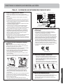
Design may vary by model number. L’aspect peut varier selon le numéro de modèle. El diseño puede variar según el número de model.
Ductless Multi Zone with Highwall Indoor Unit
Zone multi-zone conduit avec unité intérieure en hauteur
Unidad Interna para Pared Alta sin Conducto y de multi-zone

231-5000001 Rev. 7
ENGLISH
This manual contains installation instructions for Highwall indoor units. For the
FlexFit series using other style indoor units, refer to the Installation Manual supplied
with the indoor unit for the installation instructions.

31-5000001 Rev. 7 3
ENGLISH
Thank you for purchasing this Haier product. This installation manual
will help you get the best performance from your new heat pump.
For future reference, record the model and serial number located on
the label on the side of your air conditioner/heat pump, and the date
of purchase.
Staple your proof of purchase to this manual to aid in obtaining
warranty service if needed.
_______________________________________
Model number
_______________________________________
Serial number
_______________________________________
Date of purchase
To register your new Haier Duct Free system go to
http://www.haierductless.com/product-registration and input the
model/serial number information on this page. To receive a 10-year
compressor and parts warranty, registration is required within 60
days of installation.
IMPORTANT SAFETY INFORMATION ................................................................................4
INSTALLATION INSTRUCTIONS .....................................................................................6
Step 1 ...........................................................................................................9
Step 2 ..........................................................................................................11
Step 3 ..........................................................................................................13
Step 4 . . . . . . . . . . . . . . . . . . . . . . . . . . . . . . . . . . . . . . . . . . . . . . . . . . . . . . . . . . . . . . . . . . . . . . . . . . . . . . . . . . . . . . . . . . . . . . . . . . . . . . . . . .17
LIMITED WARRANTY .............................................................................................. 18
2U18MS2VH* / 3U24MS2VH* / 4U36MS2VH*
2U20EH2VH* / 3U24EH2VH* / 4U36EH2VH*
Cooling: 14°F -115°F
Heating: -4°F – 75°F
Cooling: 14°F -115°F
Heating: -15°F – 75°F
TABLE OF CONTENTS
RECORD KEEPING
OPERATING RANGE
NOTES:
• When the outdoor temperature drops below -22°F
(-30°C), the unit will stop running. The unit will turn back
on automatically when the temperature rises above the
lowest limit.
• It is recommended to have a secondary heating source(s)
available in case the temperature drops below the
operating range.
The following information lists the operating range specific to each model.

431-5000001 Rev. 7
ENGLISH
WARNING For your safety, the information in this manual must be followed to minimize the risk of fire,
electric shock, or personal injury.
• Use this equipment only for its intended purpose as
described in this manual.
• This heat pump must be properly installed in accordance
with these instructions before it is used.
• All wiring should be rated for the amperage value listed
on the rating plate. Use only copper wiring.
• All electrical work must be completed by a qualified
electrician and completed in accordance with local and
national building codes.
• Any servicing must be performed by a qualified
individual.
• All air conditioners contain refrigerants, which under
federal law must be removed prior to product disposal.
If you are getting rid of an old product with refrigerants,
check with the company handling disposal.
• These R-410A heat pumps systems require that
contractors and technicians use tools, equipment and
safety standards approved for use with this refrigerant.
DO NOT use equipment certified for R22 refrigerant
only.
WARNING RISK OF ELECTRIC SHOCK. Could cause injury or death.
• An adequate ground is essential before connecting the
power supply.
• Disconnect all connected electric power supplies before
servicing.
• Repair or replace immediately all electrical wiring that
has become frayed or otherwise damaged. Do not use
wiring that shows cracks or abrasion damage along its
length or at either end.
WARNING
This appliance is not intended for use by persons
(including children) with reduced physical, sensory or
mental capabilities, or lack of experience and knowledge,
unless they have been given supervision or instruction
concerning use of the appliance by a person responsible
for their safety. Children should be supervised to ensure
that they do not play with the appliance.
To avoid danger of suffocation, keep the plastic bag or
thin film used as the packaging material away from young
children.
Be sure not to allow foreign materials (oil, water,
etc) entering the refrigerant piping. Seal the ends of
refrigerant piping before storage.
For installation purposes, be sure to use the parts
supplied by the manufacturer or other prescribed parts.
The use of non-prescribed parts can cause serious
accidents such as the unit falling, water leakage, electric
shock, or fire.
The rated power supply of this product is 208/230
VAC/60hz/1PH. Verify the voltage is within 187~253
range before turning the equipment on.
Supply power to the heat pump should be from a
dedicated circuit that meets branch circuit ampacity
requirements.
Use a special branch circuit breaker and receptacle
matched to the power circuit capacity of the heat pump.
(Install in accordance with local technical standard for
electrical equipment .)
Do not extend the power cord.
Perform wiring work in accordance with standards so that
the air conditioner can be operated safely and positively.
Install a leakage special branch circuit breaker in
accordance with the related laws and regulations and
electric company standards.
WARNING
RISK OF FIRE. Could cause injury or death.
•
Do not store or use combustible materials, gasoline or other flammable vapors or liquids in the vicinity of this or any
other appliance.
For any service which requires entry into the
refrigerant sealed system, Federal regulations
require that the work is performed by a technician
having a Class II or Universal certification.
IMPORTANT SAFETY INFORMATION

31-5000001 Rev. 7 5
ENGLISH
READ AND SAVE THESE INSTRUCTIONS
FOR MORE HELP, VISIT HAIERAPPLIANCES.COM OR CALL THE CONSUMER HELP LINE AT 877-337-3639.
It is highly recommended that you do not open or close
the stop valves when the outdoor temperature is below
-5°F (-21°C) as this may cause refrigerant leakage.
Make sure power is turned on for at least 12 hours
after periods of being powered down in an 32 °F (0° C)
environment or lower.
Do not touch the fins of the coil. Touching the coil fins
could result in damage to the fins or personal injury such
as skin rupture.
Ensure the power circuit capacity is adequate for all loads
connected to the electrical service panel. Increase the
conductor and panel capacity if the total electrical loads
exceed the power source capacity.
Contact the power utility if the power provided is below
equipment rating plate requirements.
Be sure to install a breaker of the specified capacity.
Regulation of cables and breaker differs from each
locality, refer in accordance with local rules.
Do not use existing refrigerant lines.
Use refrigerant tubing that is clean and free of any
contamination which may cause damage to the system
including sulfur, copper oxide, dust, metal chips, powder,
oil or water.
Avoid brazing lines together. Use a continuous length of
copper tubing as oxides formed during improper brazing
techniques can damage the equipment.
Do not use copper pipes that have a collapsed, deformed,
or discolored portion (especially on the interior surface).
Otherwise, the expansion valve or capillary tube may
become blocked with contaminants.
Improper line sizing will degrade performance. Peak
pressure of R410A is much higher than R22. Use copper
tubing with adequate wall thickness.
To prevent breaking of the pipe, avoid sharp bends. Bend
the pipe with a radius of curvature of 4 in. (100 mm ) or
more.
If the pipe is bent repeatedly at the same place, it will
break.
BEFORE YOU BEGIN
Read these instructions completely and carefully.
• IMPORTANT – Save these instructions
for local inspector’s use.
• IMPORTANT – Observe all governing
codes and ordinances.
• Note to installer – Be sure to leave these instructions
with the Consumer.
• Note to consumer – Keep these instructions for
future reference.
• Skill level – A licensed certified technician (to handle
refrigerant R-410A, recovery, etc) and a qualified
electrician are required for installation and service of
this split heat pump system.
• Proper installation is the responsibility of the
installer.
• Product failure due to improper installation is not
covered under the limited warranty.
• For personal safety, this system must be properly
grounded.
• Protective devices (fuses or circuit breakers)
acceptable for installation are specified on the
nameplate of each unit.
• Make sure to avoid wiring or plumbing inside the wall
when installing.
CAUTION
• Aluminum electrical wiring may present special
problems - consult a qualified electrician.
• When the unit is in the STOP position, there is still
voltage to the electrical controls.
CAUTION
IMPORTANT SAFETY INFORMATION

631-5000001 Rev. 7
ENGLISH
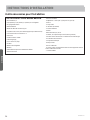
Required Tools for Installation
• 14/4 AWG stranded wire
• 5/8” (16mm), 7/8” (22mm), 1” (25mm) or Adjustable
Wrench
• R-410A Refrigerant*
• Adhesive tape*
• Conduit cable clamp 1/2”*
• Copper line set (for size, see table on page 15)
• #2 phillips screwdriver
• Drill
• R-410A flaring tool
• Hex wrench
• Hole saw 2 1/4”
• Insulation*
• Refrigerant scale
• Level
• Manifold gauge set
• Measuring tape
• Micron gauge
• Mini-split adapter (5/16”F to 1/4”M)
• Nitrogen*
• Pipe cutter
• PVC pipe
• Razor knife
• Reamer
• Saddle clamp (L.S.) w/ screws
• Sealant, non-expanding (for lineset hole)
• Soap/water solution* or gas leakage detector
• Stud finder
• Torque wrench
• Vacuum pump
• Wire strippers
• All usual and customary HVAC hand and power tools,
meters, and testing devices
* consumable
INSTALLATION INSTRUCTIONS

31-5000001 Rev. 7 7
ENGLISH
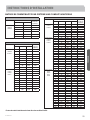
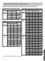
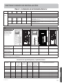
COMPATIBILITY MATRIX FOR MULTI ZONE DUCTLESS SYSYTEM
INSTALLATION INSTRUCTIONS
2U18MS2VHB & 2U20EH2VHA
Zones Combinations Total
system
capacity
Unit A Unit B
Two Zone
Unit A
Unit B
7K 7K 14K
7K 9K 16K
9K 9K 18K
7K 12K 19K
9K 12K 21K
12K 12K 24K
3U24MS2VHB & 3U24EH2VHA
Zones Combinations Total
system
capacity
Unit A Unit B Unit C
Two Zone
Unit B
Unit C
— 7K 7K 14K
— 7K 9K 16K
— 9K 9K 18K
— 7K 12K 19K
— 9K 12K 21K
— 12K 12K 24K
— 7K 18K 25K
— 9K 18K 27K
— 12K 18K 30K
Three Zone
Unit A
Unit B
Unit C
7K 7K 7K 21K
7K 7K 9K 23K
7K 9K 9K 25K
7K 7K 12K 26K
9K 9K 9K 27K
7K 9K 12K 28K
9K 9K 12K 30K
7K 12K 12K 31K*
7K 7K 18K 32K*
9K 12K 12K 33K*
4U36MS2VHB & 4U36EH2VHA
Zones Combinations Total
system
capacity
Unit A Unit B Unit C Unit D
Two Zone
Unit C
Unit D
— — 9K 18K 27K
— — 12K 18K 30K
— — 7K 24K 31K
– – 9K 24K 33K
— — 12K 24K 36K
— — 18K 18K 36K
— — 24K 18K 42K
— — 24K 24K 48K*
Three Zone
Unit B
Unit C
Unit D
— 9K 9K 9K 27K
— 7K 9K 12K 28K
— 9K 9K 12K 30K
— 7K 12K 12K 31K
— 7K 7K 18K 32K
— 9K 12K 12K 33K
— 7K 9K 18K 34K
— 9K 9K 18K 36K
— 12K 12K 12K 36K
— 7K 12K 18K 37K
— 7K 7K 24K 38K
— 9K 12K 18K 39K
— 7K 9K 24K 40K
— 9K 9K 24K 42K
— 12K 12K 18K 42K
— 7K 12K 24K 43K
— 9K 12K 24K 45K
— 12K 12K 24K 48K*
— 12K 18K 18K 48K*
Four Zone
Unit A
Unit B
Unit C
Unit D
7K 7K 7K 7K 28K
7K 7K 7K 9K 30K
7K 7K 9K 9K 32K
7K 7K 7K 12K 33K
7K 9K 9K 9K 34K
7K 7K 9K 12K 35K
9K 9K 9K 9K 36K
7K 9K 9K 12K 37K
7K 7K 12K 12K 38K
7K 7K 7K 18K 39K
9K 9K 9K 12K 39K
7K 9K 12K 12K 40K
7K 7K 9K 18K 41K
9K 9K 12K 12K 42K
7K 9K 9K 18K 43K
7K 12K 12K 12K 43K
7K 7K 12K 18K 44K
7K 7K 7K 24K 45K
9K 9K 9K 15K 45K
9K 12K 12K 12K 45K
7K 7K 9K 24K 47K*
9K 9K 12K 18K 48K*
12K 12K 12K 12K 48K*
*All indoor units must be FlexFit models

831-5000001 Rev. 7
ENGLISH
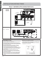
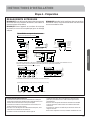
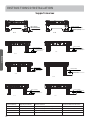
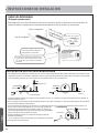
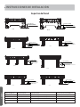
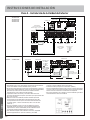
INDOOR CLEARANCES
(Appearance may vary)
This picture is for reference only. Your product may look different.
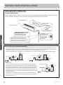
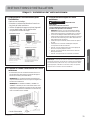
SALTWATER COAST INSTALL
• The outdoor unit should be installed at least ½ mile away from the salt water, including seacoasts and inland
waterways. If the unit installed from ½ mile to 5 miles away from the salt water, including seacoasts and inland
waterways, please follow the installation instruction below.
• Install the outdoor unit in a place (such as near buildings etc.) where it can be protected from sea breeze which
can damage the outdoor unit.
• If you cannot avoid installing the outdoor unit by the seashore, construct a protection wall around it to block the
sea breeze.
• A protection wall should be constructed with a solid material to block the
sea breeze. The height and the width of the wall should be 1.5 times larger
than the size of the outdoor unit. Also, allow at least 28” (700mm) between
the protection wall and the outdoor unit for air circulation to ventilate.
• Install the outdoor unit in a place where water can drain.
• If the above conditions cannot be met, contact Haier for assistance.
ODU
ODU
Sea breeze
Sea
ODU
Seabreeze
Sea
ODU
Seabreeze
Sea
Protectionwalls
ODU
More than 4 inches
More than 4 inches
Rear right
Left
Wrap the insulation pipe with
÷ëèĤñìöëìñê÷äóèéõòð÷ëè
åò÷÷òð÷ò÷òó
Below
Rear left
Êõõäñêèðèñ÷òé
piping directions
Right
Ìø÷÷ëèõðäïìñöøïä÷ìòñóìóè÷òäñ
appropriate length and wrap it with
÷äóèðäîìñêöøõè÷ëä÷ñòêäóìöïèé÷ìñ
÷ëèìñöøïä÷ìòñóìóèđöæø÷ïìñè
Condensate piping
ðøö÷ëäùèä
downward slope of at
least 1/4" per foot for
óõòóèõçõäìñäêè
INSTALLATION INSTRUCTIONS

31-5000001 Rev. 7 9
ENGLISH
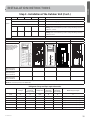
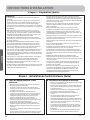
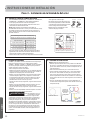
Outdoor Unit Clearances
Step 1 - Preparation
NOTE: If there is danger that the unit will fall or turn over,
fix the unit by inserting bolts, wire or other foundation
options.
NOTE: Place the unit on a level mounting base (or a plastic
pedestal) for proper drainage.
NOTE: Install the outdoor unit in a level position. Failure
to do so may result in water leakage or accumulation.
(3) Installation and maintenance space
Selection of installation location of outdoor
൳
Select the Outdoor location:
• Choose a level place solid enough to bear the weight and
vibration of the OD unit and where the operation noise will
not be amplified.
• Choose a location where the hot air discharge and/or noise
will not create a nuisance for neighbors.
• Ensure there is sufficient space to maneuver the OD unit
into place.
• Ensure there is sufficient space and no obstructions for the
air inlet and outlet.
• I nstall the unit’s power/communication wiring at least
10 feet away from television and radio sets to prevent
interference.
• Ensure any moisture sensitive items are kept away from the
condensate drain path of the OD unit.
• Choose a location not affected by heavy snowfall or wind.
• To prevent wind exposure, install a wind baffle.
INSTALLATION INSTRUCTIONS

10 31-5000001 Rev. 7
ENGLISH
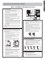
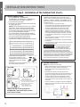
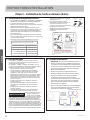
Step 2 - Installation of the Indoor Unit
A. Select the Indoor location:
• Do not expose the unit to unusual heat sources or
steam outlets.
• Select a location where there are no obstacles in
front of the unit.
• Make sure that condensate drainage can be
conveniently routed away.
• Do not install near a doorway.
• Ensure that the space around the left and right of
the unit is more than 4”. The unit should be installed
as high on the wall as possible but allow a minimum
of 4” from the ceiling.
• Use a stud finder to locate and mark stud locations
for mounting and to prevent unnecessary damage
to the wall.
• Install in a location that is strong enough to
withstand the full weight and vibration of the unit.
• Leave enough space to allow access for routine
maintenance.
• Select a location that gives easy access to removing
and cleaning air filters.
• Install in a location that is 3 ft. or more away from
other electrical appliances, such as televisions and
audio devices.
B. Install the Mounting Plate
• Remove plastic bag, tape, and mounting plate from
the back of the indoor unit.
• Place the mounting plate on the wall in the desired
location taking into account the minimum clearances
necessary for proper operation.
• Using a level, verify that the mounting plate is
horizontal and mark the screw locations.
• Attach the mounting plate to the wall with the
supplied screws.
• If not able to align all screw holes with studs, wall
anchors are supplied.
• Be sure that the mounting plate has been attached
firmly and that applied weight is evenly distributed
by each screw. (At least one screw in wall stud,
others can use wall anchors.)
• The piping for the indoor unit may be routed to and
from the unit in one of several directions: left, left
rear, right, right rear, or right below. See Illustration
on page 7.
Step 1 - Preparation Cont.
NOTES:
• OD unit cannot hang from a ceiling or be stacked.
• If installing the OD unit with a fence or rail guard around it,
ensure that accumulated snow, debris, etc… will not block
the air inlet or the coil exchanger.
• Ensure ventilation in case of refrigerant leakage. R-410A is
a safe, nontoxic, and nonflammable refrigerant.
• Avoid installing the OD unit where corrosive gases, such as
sulfur oxides, ammonia, and sulfurous gas are produced. If
unavoidable, consult with an installation specialist about
using a corrosion-proof or anti-rust additive to protect the
unit coils.
• Do not install the outdoor unit near the edge of a balcony.
Otherwise, children may climb onto the outdoor unit and fall
off of the balcony.
• Do not install the outdoor unit in the following areas: Areas
heavily laden with oil or greasy vapors such as kitchens. Oils
and grease will create sticky layer on the coil and also cause
drainage problems, thus degrade unit performance.
• Corrosive areas that can potentially have combustible
gas leaks, contain suspended fibers or flammable dust, or
flammables such as paint thinner or gasoline can cause fires.
• Areas that contain small animals, rodents, reptiles or insects
that can infiltrate the equipment and cause damage to
internal components.
• Area where animals may urinate on the unit or ammonia
may be generated.
• If the outdoor unit must be installed in an area within easy
reach of the general public,Install as necessary a protective
fence or the like to prevent their access.
• If the outdoor unit is installed in a cold region that is
affected by snow accumulation, snow fall, or freezing, take
appropriate measures to protect it from those elements. To
ensure a stable operating, install inlet and outlet ducts.
• Make sure the outdoor unit is installed level and is stable.
Install snow protection hood as necessary.
• Avoid salty places such as the seaside for installation where
air conditioner trouble is liable to occur.
• Install the outdoor unit in a location that is away from
exhaust or the vent ports that discharge vapor, soot, dust,
or debris.
• Install the unit where it will not be tilted by more than 3°.
However, do not install the unit with it tilted towards the
side containing the compressor.
• When installing the outdoor unit where it may exposed to
strong wind, fasten it securely.
• It is recommended that unit be installed under a canopy or
elevated on a high stand.
• Protect the drain line from freezing in areas where
temperature drops to 32°F (0°C) or lower.
• Please set up the outdoor unit in a high place and please
do not arrange the frame of installed stand under the
drain port, because the water dropped from the drain port
repeats freezing and accumulating, and may block the drain
port.
• Do not use mineral oils on flared parts. Prevent mineral
oil from entering the refrigerant system. Introduction of
mineral oil may reduce the system life.
• Be sure to use an inert gas such as nitrogen while brazing
any refrigerant lines to prevent any oxidation
• Be sure not to exceed refrigerant tubing length limits
mentioned in table on page 15 for different models to
ensure smooth operation of the unit. Otherwise the
equipment life cannot be guaranteed.
INSTALLATION INSTRUCTIONS

31-5000001 Rev. 7 11
ENGLISH
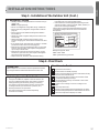
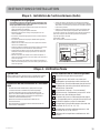
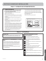
D. Electrical Connections for the Indoor Unit
NOTE: Be certain all wiring complies with local building
codes and NEC and that the supply voltage for this
system is correct.
• Place the indoor unit on a solid work surface before
making electrical connections.
• To make the electrical connections for the indoor
unit, both the outer plastic and inner galvanized
steel cover plate must be removed.
• Raise the front cover to access the screws for
removing these covers.
• Rout the 14/4 AWG wiring through the slot in the
back of the unit and into the front access panel.
• Using a wire stripper, remove the insulation and
separate the 4 wires.
• Make wiring connections at each terminal according
to wiring diagram. (Take note of the color of the
wire at each terminal and ensure the wires are
connected to the outdoor unit accordingly.)
• Ensure each wire is under the screw terminal plate
and the plate is tightened.
• Ensure the 14/4 cable is secured under the strain
relief bracket.
• After the terminal block wiring is completed, replace
both cover plates and lower the front casing.
E. Mount Indoor Unit to Mounting Plate
• Bundle the refrigerant piping, drain piping, and wiring
with tape and carefully rout the bundle through the
piping hole.
• With the top of the indoor unit closer to the wall,
hang the indoor unit on the upper hooks of the
mounting plate. Slide the unit slightly side to side to
verify proper placement.
• Rotate the lower portion of the indoor unit to the
mounting plate, pushing the unit up slightly, rotate
the lower part of the unit fully against the wall, then
pull down do the lower hooks engage the brackets.
(see illustration)
• Verify the unit is secured and flush to the wall.
• Indoor Unit installation is finished at this time.
F. Condensate Drainage Pipe
• Verify the condensate drain line has a constant pitch
downward for proper water flow. There should be
no kinks or rises in the tubing which may cause a
trapping effect of the water (see illustration).
Optional: Can use PVC pipe by connecting a 1” ID
PVC pipe to the drain line coming out of the wall and
running to desired location.
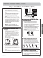
Outdoor unit
Power Wiring
3
2
1)
(N)
(L )
(C
2
1)
(N)
(L
Indoor unit
Control Wiring
4 Wire - 14 AWG
Stranded
To Service Disconnect
1
2
3
=White
=Black
=Red
=Green
Sugested Colors
230 Volt Supply. 1 to L1, 2 to L2.
Strain Relief
Brackets
mounting plate
Step 2 - Installation of the Indoor Unit (Cont.)
G. To Remove the Indoor Unit
• Slightly raise the entire unit.
• Pull the lower portion of the unit off the lower hooks
and pull slightly away from the wall.
• Lift the upper portion of the unit off the upper hooks.
C. Install the Tubing
• Always use new clean copper tubing. Never reuse
tubing if replacing an existing system.
• Measure and mark the location where the piping hole
is to be drilled.
• If pipe location will be on the left side of the unit,
follow these steps to move the drain pipe.
1. Remove the stopper in the left drain hole and
knockout the molded plug inside the port.
2. Transfer the corrugate drain hose from the right side
to the left side.
3. Insert stopper into right side drain port. Using soap
as a lubricant and a small screwdriver will allow for
easier seating of the stopper.
• Drill the lineset hole using a 2 1/4” hole saw. Angle
the drill with a downward pitch to the outside wall so
that the outside wall hole will be at least a ¼” lower
than the inside hole. This allows for proper drainage
of condensate.
• Install the lineset hole flange at the hole opening on
the inside wall.
NOTE: The flange is prescored. It may be necessary
to modify the flange to fit properly behind the wall unit
housing.
It becomes
high midway. The gap with the
ground is too small There is the bad
smell from a sewer
It waves.
The end is imm-
ersed in water.
Less than
5cm
INSTALLATION INSTRUCTIONS

12 31-5000001 Rev. 7
ENGLISH
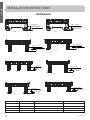
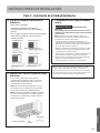
Wall Brackets
35
N
1.84in (46mm)
0.236in (6mm)
Ø 2 1/4in (57mm)
40 N
2.795in (71mm)
0.472in (12mm)
Ø 2 1/4in (57mm)
4.961in (126 mm)
1.417in (36mm)
50 N
Ø 2 1/4in (57mm) 1.417in (36mm)
4.882in (124mm)
Ø 2 1/4in (57mm)
70 N
5.906in (150mm)
1.417in (36mm)
Ø 2 1/4in (57mm)
100 N
4.961in (126mm)
1.614in (41mm)
50 T
Ø 2 1/4in (57mm) 1.614in (41mm)
4.882in (124mm)
Ø 2 1/4in (57mm)
70 T
3.150in (80mm)
1.85in (47mm)
35 T
Ø 2 1/4in (57mm)
Capacity (BTUh) Bracket Style Part Number Factory Reference Number
07K/09K/12K 35N/35T/40N WJ65X23038/WJ65X23240/WJ65X23038 10101275/10103071/10101275
15K/18K 50N/50T/70N WJ65X23251/WJ65X23251/WJ65X23056 10102598/10102598/10102740
24K 70N/70T WJ65X23056/WJ65X23056 10102740/10102740
30K/36K 100N WJ65X22785 10103059
INSTALLATION INSTRUCTIONS

31-5000001 Rev. 7 13
ENGLISH
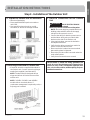
Step 3 - Installation of the Outdoor Unit
A. Prepare the Outdoor Unit for Installation
• Remove all packaging.
• Place supplied vibration pads onto outdoor
unit’s feet.
• Use team lift to place the unit on a solid
foundation, 8” above the average snowfall.
B Attaching Drain Elbow to Outdoor Unit
• If required, attach the supplied drain elbow to
the outdoor unit. Connect extension piping as
needed (not supplied). (see illustration)
NOTE: The drain elbow is designed with an
air gap and will not sit flush to bottom of the
outdoor unit.
NOTE: 2U20EH*, 3U24EH* and 4U36EH*
models will not use a drain elbow. If
condensate management is required by code, a
3rd party pan is needed.
INSTALLATION INSTRUCTIONS
NOTE: Failure to follow the wiring guidelines can
result in control board damage and communication
issues (E7 error code). This includes improper wire
size, use of solid core wire, midline splicing and poor
terminal connections.
C. Electrical Connections for the Outdoor
Unit
WARNING RISK OF ELECTRIC SHOCK.
Could cause injury or death.
Make sure power is off before touching wires.
NOTE: Be certain all wiring complies with local
building codes and NEC and that the supply
voltage for this system is correct.
• Connect the wiring for both the power source
and the indoor wiring using a conduit cable
bracket on the side of the outdoor unit
• Using a wire stripper, remove the insulation
and separate the wires.
• Verify that the wiring connections match the
indoor connections wire for wire.
• Ensure each wire is under the screw terminal
plate and the plate is tightened.
• Ensure the 14/4 wire cable is secured under the
strain relief bracket.
• Verify that all connections are secured

14 31-5000001 Rev. 7
ENGLISH
Step 3 - Installation of the Outdoor Unit (Cont.)
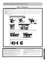
D. Wiring Error Check
• This unit is capable of automatically checking for wiring errors
between the indoor and outdoor units.
• To enter the wiring error check test, remove power to unit,
place all 4 DIP switches on the test board in the “ON” position
(illustration 6). Reapply power to the unit. The system will now
enter “Wiring Error Check”
• The numeric display will initialize and begin to alternate
between the compressor working frequency (a number
representing the Hz value) and “CH” (Checking).
• As the check is being performed, all units that are properly
connected will be indicated by the corresponding LED for that
circuit being lit constantly. (LED 1 = piping circuit A, LED 2 =
piping circuit B, ...)
• After the check has completed, if all wiring is correct,
the numeric display will indicate “0” and the single LEDs
representing the individual circuits for the connected indoor
units will be lit constantly.
• If there are any miswired units, the numeric display will flash
“EC” (error connection), and th corresponding LED for the
miswired circuit will flash. Check and correct the wiring as
needed.
• Refer to the chart shown below. (Table 2)
• When the test is complete, remove power to the system and
return the 4 DIP switches to the OFF position. Reapply power
to the the system. The test is complete.
• If the self-check is not possible, check the indoor unit wiring
and piping in the usual manner.
Outdoor unit
Power Wiring
3
2
1)
(N)
(L )
(C
2
1)
(N)
(L
Indoor unit A
Control Wiring
4 Wire - 14 AWG
Stranded
43 43
To Service Disconnect
1
2
3
=White
=Black
=Red
=Green
ABCD
Sugested Colors
230 Volt Supply. 1 to L1, 2 to L2.
Indoor unit B Indoor unit C Indoor unit D
3
2
1)
(N)
(L )
(C
3
2
1)
(N)
(L )
(C
3
2
1)
(N)
(L )
(C
Strain Relief
Brackets
Only on FlexFit 3U & 4U
and Arctic 2U & 3U
Only on FlexFit 4U
and Arctic 2U & 3U Only on FlexFit 3U
Diagnostic and Control
Models: 4U36MS2VHB
3U24EH2VHA
3U24MS2VHB
2U20EH2VHA
4U36EH2VHA
Models: 2U18MS2VHB
Outdoor unit
Power Wiring
3
2
1)
(N)
(L )
(C3
2
1)
(N)
(L )
(C
Indoor unit 2
Control Wiring
4 Wire - 14 AWG
Stranded
To Service Disconnect
1
2
3
=White
=Black
=Red
=Green
Sugested Colors
230 Volt Supply. 1 to L1, 2 to L2.
Indoor unit 1
2
1)
(N)
(L
Strain Relief
Brackets
INSTALLATION INSTRUCTIONS
Only on 3U24MS*,
4U36MS*, 2U20EH*,
3U24EH*, and 4U36EH*
Only on 3U24MS*,
4U36MS*, 2U20EH*,
3U24EH*, and 4U36EH* Only on 3U24MS

31-5000001 Rev. 7 15
ENGLISH
Step 3 - Installation of the Outdoor Unit (Cont.)
Connections Cautions
Model 4U36MS2VHB 3U24EH2VHA 3U24MS2VHB 2U18MS2VHB 2U20EH2VHA
Connection priority is
largest indoor unit on
lowest terminal set (D),
and install remaining
indoor units from
bottom to top.
A
B
C
When there are 2
indoors, the prior
service valves are
D C C B C B B A B A
When there are 3
indoors, the prior
service valves are
D C B C B A C B A / /
When there are 4
indoors, the prior
service valves are
D C B A / / / /
NOTE: For better oil return and more reliable system, please execute as the above when connecting indoor unit.
NOTE: No connection priority on 4U36EH2VHA.
LED 1 2 3 4 5 Message
Status
OFF Unit not connected
ALL Flashing Automatic checking impossible, all units connected wrong
ALL ON All units connected correctly
ON Flashing Flashing ON Flashing ON: unit connected correctly
Flashing: unit connected wrong, need to change the wiring manually
between 2, 3, and 5
ON Flashing Flashing ON ON ON: unit connected correctly
Flashing: unit connected wrong, need to change the wiring manually
between 2 and 3
Only one LED flashing
A
B
INSTALLATION INSTRUCTIONS
Model Number Factory
Charge Total Pipe
Length of
factory charge
Additional
charge rule* Branch
Maximum
pipe length
System
Maximum
pipe length Minimum pipe length
Unit oz ft oz/ft ft ft ft
2U20EH2VH* 99 100 0.2 82 164 6 ft per indoor and 20 ft per system
2U18MS2VH* 49.5 50 0.2 65 98 6 ft per indoor and 20 ft per system
3U24EH2VH* 99 100 0.2 82 197 6 ft per indoor and 20 ft per system
3U24MS2VH* 67 75 0.2 82 197 6 ft per indoor and 20 ft per system
4U36MS2VH* 113 100 0.2 82 230 6 ft per indoor and 25 ft per system
4U36EH2VH* 113 131 0.2 82 230 6 ft per indoor and 25 ft per system
Refrigerant Charge and Pipe Length Information

16 31-5000001 Rev. 7
ENGLISH
Step 3 - Installation of the Outdoor Unit (Cont.)
G. System Evacuation
NOTE– Do not open service valve.
• Remove the suction line cap and attach a manifold
gauge, micron gauge, and vacuum pump to
the suction line port using adapter AD-87 (see
illustration).
• Evacuate the system to at least 350 microns.
• Close the vacuum pump valve and check the micron
gauge. If the gauge rises above 150 microns in 60
seconds, the evacuation is incomplete or there
is a leak in the system. If the gauge does not rise
above 150 microns in 60 seconds, the evacuation is
complete.
• Once evacuation is complete, remove the adapter
and hose connection from the suction line port and
replaced the cap.
F. Leak Test
2U18MS* and 3U24MS* do not have main service
valves. Perform the following steps for EACH line set.
4U36MS*, 2U20EH*, 3U24EH*, and 4U36EH* have a
main service valve. Performing the following steps will
test ALL line sets.
• Remove the cap on the service valve.
• Using a tank of dry nitrogen and approved regulator,
charge the system with 150 psig of dry nitrogen
using mini-split adapter to connect the valve.
• Check for leaks at the flare fittings using soap
bubbles or another detection device. If a leak is
detected, make repairs to the fittings and recheck.
If no leaks are detected within 3 minutes, proceed.
• Using the same tank/regulator, charge the system
to 300 psig.
• Check for leaks as earlier. If no leaks are detected
within 3 minutes, proceed.
• Using the same tank/regulator, charge the system
to 500 psig.
• Check for leaks as earlier. Keep system pressurized
for at least 20 minutes.
WARNING Do not use acetylene, oxygen or
compressed air or mixtures
containing air, oxygen, or combustible gases for
pressure testing. Do not use mixtures of hydrogen
containing refrigerant and air above atmospheric
pressure for pressure testing as they may become
flammable and could result in an explosion. Refrigerant,
when used as a trace gas, should only be mixed with dry
nitrogen for pressurizing units. Failure to follow these
recommendations could result in death or serious
injury as well as equipment or property damage.
E. Install Copper Lineset
• For 2U20EH2VH*, 2U18MS2VH*,
3U24EH2VH*, 3U24MS2VH*, 4U36MS2VH*,
and 4U36EH2VH* see table on page 15.
• Cut the line set to length.
• Place nut over the pipe and then flare with the
R-410A flaring tool.
NOTE: Follow standard practices for creating
pipe flares. When cutting and reaming the
tubing, use caution to prevent dirt or debris
from entering the tubing. Remember to place
nut over the tubing before flaring.
• To join the line set, directly align the tubing
flare to the fitting on the other pipe. Slide the
nut onto the fitting and hand tighten.
• Torque the fittings according to the
specifications shown in the torque chart below.
Forced fastening without careful centering may
damage the threads and cause a refrigerant leak.
Pipe Diameter(Ǜ) Fastening torque
Liquid side6.35mm(1/4") 18N.m/13.3Ft.lbs
Liquid/Gas side9.52mm(3/8") 42 N.m/30.1Ft.lbs
Gas side 12.7mm(1/2") 55N.m/40.6Ft.lbs
Gas side 15.88mm(5/8") 60 N.m/44.3Ft.lbs
• Two wrenches are required to
join the flare connection; one
standard wrench and one torque
wrench adjusted to the proper
settings.
• Repeat the process for attaching
the other end of the line set.
Half union Flare nut
Torque wrenc
h
Spanner
Outdoor unit
Indoor unit
A
B
Outdoor unit
Indoor unit
A
B
A
B
Outdoor unit
Indoor unit
Oil trap
CAUTION*
Max. Elevation: A Max
= 33ft / 10m (09k / 12k)
= 50ft / 15m (18k / 24k)
In case the height of A is more than
15ft / 5m, an oil trap should be
installed every 16-23ft /5-7m
Max. Length: B Max
= 50ft / 15m (09k / 12k)
= 83ft / 25m (18k / 24k)
Ɣ
Ɣ
Ɣ
*NOTE: Oil trap is only required for
2U18MS2VH*, other multi-split systems
don’t require oil trap.
INSTALLATION INSTRUCTIONS

31-5000001 Rev. 7 17
ENGLISH
Step 4 - Final Check
System Test
Please explain to the customer how to operate the system
by using the Owner’s Manual found with the indoor unit.
Check Items for Test Run
No gas leak from linesets?
Are the linesets insulated properly?
Are the connecting wirings of indoor and outdoor firmly
inserted to the terminal block?
Is the connecting wiring of indoor and outdoor fixed?
Is condensate draining correctly?
Is the ground wire securely connected? Is the indoor
unit securely fixed?
Is power source voltage correct according to local
code?
Is there any odd noise?
Does the cooling temperature drop between 20-30°F?
Does the heating temperature raise between 35-40°F?
Is the room temperature display accurate?
Explaining Operation To the End User
• Using the User Manual, explain to the user how to use
the air conditioner/heat pump, (the remote controller,
adding/removing the air filters, placing or removing
the remote controller from the remote control holder,
cleaning methods, precautions for operation, etc.)
• Review precautions for operation.
• Recommend that the user read the Operating
Instructions carefully.
Step 3 - Installation of the Outdoor Unit (Cont.)
H. Refrigerant Charging
• Add any additional refrigerant after evacuation using a
digital scale.
NOTE: Charge liquid only.
• Fill out the refrigerant charge label using indelible ink.
• Place the factory refrigerant charge found in table on
page 15.
• Place the amount of additional refrigerant added in
box number 2.
• Add boxes 1 and 2 together and place the value in the
sum box (D).
• Adhere the filled out label in the proximity of the
product charging port and under the outside unit valve
cover.
• If no sticker found, write amounts on outdoor unit with
permanent marker above the charging port.
• Remove the cap from the liquid line valve. Using a hex
wrench, open the valve, then replace and tighten the
cap securly to avoid leaks.
• Remove the cap from the suction line valve. Using a
hex wrench, open the valve, then replace and tighten
the cap securly to avoid leaks.
• Wrap the line set, drain line, and 14/4 AWG wiring
starting at the bottom of the bundle with an overlap
type wrap until you reach the piping hole.
• Use a sealant to seal the piping hole opening on both
sides of the wall in order to prevent drafts, weather, or
pests from entering the building.
This product contains fluorinated greenhouse gases
covered by the Kyoto Protocol. Do not vent into the
atmosphere.
11+2= oz
R410A
2oz
2=
1=
B
C
D
FE
oz
A
Contains fluorinated greenhouse gases
covered by the Kyoto Protocol
Refrigerant type: R-410A
GWP* value: 2088
GWP = global warming potential
INSTALLATION INSTRUCTIONS

18 31-5000001 Rev. 7
ENGLISH
NOTES

31-5000001 Rev. 7 19
ENGLISH
LIMITED WARRANTY
Staple your receipt here. Proof of the original purchase
date is needed to obtain service under the warranty.
• Damage from improper installation.
• Damage in shipping.
• Defects other than from manufacturing (i.e.,
workmanship or materials).
• Damage from misuse, abuse, accident, alteration, lack
of proper care and/or regular maintenance, or incorrect
electrical voltage or current.
• Damage resulting from floods, fires, wind, lightning,
accidents or similar conditions.
• Damage from installation or other services performed
by other than a licensed HVAC technician.
• Labor and related services for repair or installation of
the Product.
• A Product purchased from an online retailer.
• Damage as a result of subjecting Product to an
atmosphere with corrosives or high levels of
particulates (such as soot, aerosols, fumes, grease).
• A Product sold and/or installed outside of the 50 United
States, the District of Columbia, or Canada.
• Batteries for the controller and other accessories
provided with the Product for installation (e.g., plastic
hose).
• Normal maintenance, such as cleaning of coils, cleaning
filters, and lubrication.
• For Product installed in non-owner occupied
applications, Product that has not been maintained
annually by a licensed HVAC technician (proof required).
For The Period Of: Haier Will Replace:
5 year limited parts
warranty
From the date of the
original purchase
This limited warranty cover all defects in workmanship or material for the mechanical and
electrical parts contained in the Product (“Defective Parts”) for a period of 5 years from the
Date of Purchase. Haier will provide new or refurbished parts, or a replacement for all or part
of the unit, at its sole discretion, to your licensed HVAC technician installer. This warranty also
covers all defects in workmanship or material for the unit controller for a period of 1 year. The
remote controller is covered by 1-year accessory warranty. The ductless system is covered
by standard warranty. Haier will provide a new or refurbished controller, at its sole discretion.
7 year compressor
warranty from the date
of the original purchase
The compressor contained in this product is warrantied for a period of 7 years from the Date
of Purchase. Haier will provide a new or refurbished compressor, or a replacement for all or
part of the unit, at its sole discretion, to your licensed HVAC technician installer.
For the product models listed on Attachment 1 (the “Product”), this Standard Limited Warranty is provided to the Original
Owner of the Product:
WHAT IS THE DATE OF PURCHASE
WHO IS COVERED
HOW CAN YOU GET SERVICE
THIS WARRANTY DOES NOT COVER
The “Date of Purchase” is the date that the original installation is complete and all product start-up procedures have
been properly completed and verified by the installer’s invoice. If the installation date cannot be verified, then the
Date of Purchase will be sixty (60) days after the manufacture date, as determined by the Product’s serial number. You
should keep and be able to provide your original sales receipt from the installer as proof of the Date of Purchase. In new
construction, the Date of Purchase will be the date the owner purchased the residence from the builder.
Contact your licensed HVAC technician installer. All installation and service must be performed by a licensed HVAC
technician. Failure to use a licensed HVAC technician for installation of this Product voids all warranty on this Product..
Owner occupied: The “Original Owner” of this product, which means the original owner (and his or her spouse) of the
residence where the Product was originally installed. Subject to the law of the state or province where the Product is
installed, this warranty is not transferable to subsequent owners or if the product is moved to a different residence after
the initial installation. Non-owner occupied: This limited warranty is provided for product 1) installed in a) single family
or multi-family non-owner occupied residential buildings, or b) non-industrial commercial applications, (such as office
buildings, retail establishments, hotels/motels) where the product is not subjected to an atmosphere with corrosives or
high levels of particulates (such as soot, aerosols, fumes, grease), and 2) if the product is maintained annually by a licensed
HVAC technician (proof of annual maintenance is required). The “Original Owner” of the product, means the original
owner of the building where the product was originally installed. For new construction, the purchaser of the building
from the builder will also be considered an original owner. This warranty is not transferable to subsequent owners or if the
product is moved to a different location after the initial installation.

20 31-5000001 Rev. 7
ENGLISH
LIMITED WARRANTY
10 YEAR STANDARD REGISTERED LIMITED WARRANTY
ATTACHMENT 1
THIS LIMITED WARRANTY IS GIVEN IN LIEU OF ALL OTHER WARRANTIES, EXPRESS OR IMPLIED, INCLUDING
THE WARRANTIES OF MERCHANTABILITY AND FITNESS FOR A PARTICULAR PURPOSE.
All “Indoor and Outdoor Products,” identified in Attachment 1, registered by the installer or the Original Owner within 60
days of the Date of Purchase shall receive a Standard Registered Limited Warranty, which shall be identical to the Standard
Base Warranty, except that the Limited Parts Warranty shall be for a term of 10 Years and the Limited Compressor Warranty
shall be for a term of 10 years. All Product not registered within 60 days of the Date of Purchase shall be subject to the
Standard Base Warranty. Some states and provinces do not allow warranty terms to be subject to registration; in those
states and provinces the longer terms for Limited Parts Warranty and the Limited Compressor Warranty apply.
The remedy provided in this warranty is exclusive and is granted in lieu of all other remedies. This warranty does not cover
incidental or consequential damages. Some states and provinces do not allow the exclusion of incidental or consequential
damages, so this limitation may not apply to you. Some states and provinces do not allow limitations on how long an implied
warranty lasts, so this limitation may not apply to you. This warranty gives you specific legal rights and you may also have
other rights which vary by state and province. This warranty covers units within the 50 United States, the District of Columbia
and Canada. This warranty it provided by GE Appliances a Haier company, Louisville, KY 40225.
The “Product” is defined as Haier brand Ductless Split Units. The “Product” contains 2 sub-categories of goods: “Indoor and
Outdoor Products” and “Selected Installation Products,” which are further defined below: “Indoor and Outdoor Products”
can further be identified by the following model number descriptions: 1U*, 2U*, 3U*, 4U*, AB*, AD*, AL*, AM*, AW*, AF*,
MVA* MVH* “Selected Installation Products,” identified by the following model number descriptions: PB-* FQG-*, AH1-*,
MS1-* and MS3-*
La page charge ...
La page charge ...
La page charge ...
La page charge ...
La page charge ...
La page charge ...
La page charge ...
La page charge ...
La page charge ...
La page charge ...
La page charge ...
La page charge ...
La page charge ...
La page charge ...
La page charge ...
La page charge ...
La page charge ...
La page charge ...
La page charge ...
La page charge ...
La page charge ...
La page charge ...
La page charge ...
La page charge ...
La page charge ...
La page charge ...
La page charge ...
La page charge ...
La page charge ...
La page charge ...
La page charge ...
La page charge ...
La page charge ...
La page charge ...
La page charge ...
La page charge ...
-
 1
1
-
 2
2
-
 3
3
-
 4
4
-
 5
5
-
 6
6
-
 7
7
-
 8
8
-
 9
9
-
 10
10
-
 11
11
-
 12
12
-
 13
13
-
 14
14
-
 15
15
-
 16
16
-
 17
17
-
 18
18
-
 19
19
-
 20
20
-
 21
21
-
 22
22
-
 23
23
-
 24
24
-
 25
25
-
 26
26
-
 27
27
-
 28
28
-
 29
29
-
 30
30
-
 31
31
-
 32
32
-
 33
33
-
 34
34
-
 35
35
-
 36
36
-
 37
37
-
 38
38
-
 39
39
-
 40
40
-
 41
41
-
 42
42
-
 43
43
-
 44
44
-
 45
45
-
 46
46
-
 47
47
-
 48
48
-
 49
49
-
 50
50
-
 51
51
-
 52
52
-
 53
53
-
 54
54
-
 55
55
-
 56
56


GE AD18SL2VHB Guide d'installation
- Catégorie
- Climatiseurs split-system
- Taper
- Guide d'installation
dans d''autres langues
- English: GE AD18SL2VHB Installation guide
- español: GE AD18SL2VHB Guía de instalación