Force RC FCEF060001 Le manuel du propriétaire
- Catégorie
- Jouets télécommandés
- Taper
- Le manuel du propriétaire

F-18 Blue Angel®
®
Instruction Manual
Manuel d’utilisation

EN
Safety Precautions and Warnings
14+ AGE RECOMMENDATION:
Not for children under 14
years. This is not a toy.
NOTICE
All instructions, warranties and other collateral documents are subject to change at the sole discretion of Horizon Hobby, LLC. For up-to-date product literature, visit
www.forcerc.com and click on the support tab for this product.
MEANING OF SPECIAL LANGUAGE:
The following terms are used throughout the product literature to indicate various levels of potential harm when operating this product:
WARNING: Procedures, which if not properly followed, create the probability of property damage, collateral damage, and serious injury OR create a high probability of
superfi cial injury.
CAUTION: Procedures, which if not properly followed, create the probability of physical property damage AND a possibility of serious injury.
NOTICE: Procedures, which if not properly followed, create a possibility of physical property damage AND little or no possibility of injury.
WARNING: Read the ENTIRE instruction manual to become familiar with the features of the product before operating. Failure to operate the product
correctly can result in damage to the product, personal property and cause serious injury.
This is a sophisticated hobby product. It must be operated with caution and common sense and requires some basic mechanical ability. Failure to operate this Product
in a safe and responsible manner could result in injury or damage to the product or other property. This product is not intended for use by children without direct adult
supervision. Do not use with incompatible components or alter this product in any way outside of the instructions provided by Horizon Hobby, LLC. This manual contains
instructions for safety, operation and maintenance. It is essential to read and follow all the instructions and warnings in the manual, prior to assembly, setup or use, in
order to operate correctly and avoid damage or serious injury.
As the user of this product, you are solely responsible for operating in a manner that does not endanger yourself and others or result in damage to the product or the
property of others.
• Always keep a safe distance in all directions around your model to avoid
collisions or injury. This model is controlled by a radio signal subject to
interference from many sources outside your control. Interference can cause
momentary loss of control.
• Always operate your model in open spaces away from full-size vehicles, traffi c
and people.
• Always carefully follow the directions and warnings for this and any optional
support equipment (chargers, rechargeable battery packs, etc.).
• Always keep all chemicals, small parts and anything electrical out of the reach
of children.
• Always avoid water exposure to all equipment not specifi cally designed and
protected for this purpose. Moisture causes damage to electronics.
• Never place any portion of the model in your mouth as it could cause serious
injury or even death.
• Never operate your model with low transmitter batteries.
• Always keep aircraft in sight and under control.
• Always use fully charged batteries.
• Always keep transmitter powered on while aircraft is powered.
• Always remove batteries before disassembly.
• Always keep moving parts clean.
• Always keep parts dry.
• Always let parts cool after use before touching.
• Always remove batteries after use.
• Always ensure failsafe is properly set before fl ying.
• Never operate aircraft with damaged wiring.
• Never touch moving parts.
F-18 Blue Angel
2

EN
Box Contents
Quick Start Information
Transmitter
Setup
1. Blank (Acro) Model
2. Servo Reversing: Normal
3. Travel Adjust (All Surfaces): 100%
Dual Rates
Extreme Flying Normal Flying
Ail =14mm
=14mm
=10mm
=10mm
Ele =12mm
=12mm
=8mm
=8mm
EXPO
(Soft center)
High Low
Ail 15% 5%
Ele 20% 5%
Center of
Gravity (CG) 80–85mm back from leading edge at
the root.
Flight Timer
Setting 3 minutes
Table of Contents
~23.3 oz
(~660g)
37.8 in (960mm)
26.6 in (675mm)
Specifi cations
Motor: Brushless Outrunner: KV3150 (FMMKV3150)
Installed
ESC: 40A Brushless Switch Mode (FMMPAC113) Installed
(5) Servos
(FMMSER9GP, FMMSER9G54, FMMSER9GR) Installed
Recommended Receiver: Spektrum™ AR636A
6-Channel Sport Receiver Required to
Complete
Recommended Battery: 14.8V 2400mAh 30C
4S LiPo Battery, 12AWG: EC3 (KXSB0016) Required to
Complete
Recommended Battery Charger:
4-cell Li-Po battery balancing charger Required to
Complete
Recommended Transmitter:
Full-Range 2.4GHz with Spektrum™
DSM2®/DSMX® technology. (DX6i and above)
Required to
Complete
190.7 sq in
(12.3 sq dm)
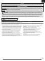
Safety Precautions and Warnings ...........................................................................2
Box Contents .........................................................................................................3
Specifi cations ........................................................................................................3
Table of Contents ...................................................................................................3
Prefl ight .................................................................................................................4
Model Assembly ....................................................................................................4
PNP Receiver Selection and Installation .................................................................6
Battery Installation and ESC Arming .......................................................................7
Center of Gravity (CG) ...........................................................................................7
Clevis Installation and Control Centering ................................................................8
Control Horn and Servo Arm Settings .....................................................................8
Power Components Service ...................................................................................9
Control Surface Direction .....................................................................................10
Flying Tips and Repairs ........................................................................................10
Post Flight............................................................................................................11
Troubleshooting Guide .........................................................................................12
AMA National Model Aircraft Safety Code .............................................................13
Limited Warranty .................................................................................................14
Warranty and Service Contact Information ...........................................................14
Replacement Parts ...............................................................................................27
If you own this product, you may be required to register with the FAA.
For up-to-date information on how to register with the FAA, please visit
https://registermyuas.faa.gov/.
For additional assistance on regulations and guidance on UAS usage,
visit knowbeforeyoufl y.org/.
3

EN
Model Assembly
A
B
Prefl ight
1 Remove and inspect contents.
2 Read this instruction manual thoroughly.
3 Charge fl ight battery.
4 Fully assemble airplane.
5 Install the fl ight battery in the aircraft (once it has been fully charged).
6 Check the Center of Gravity (CG).
7 Bind aircraft to your transmitter.
8 Make sure linkages move freely.
9 Perform the Control Direction Test with the transmitter.
10 Perform the AS3X Control Direction Test with the aircraft.
11 Adjust fl ight controls and transmitter.
12 Perform a radio system Range Test.
13 Find a safe open area to fl y.
14 Plan fl ight for fl ying fi eld conditions.
Horizontal Stabilizer Installation
1. Apply CA to the base of the horizontal stabilizer where it meets the
fuselage.
2. Apply CA in the slot in the fuselage where the horizontal stabilier fi ts.
3. Fit the horizontal stabilizer in the slot. Ensure the control horn faces down
toward the bottom of the fuselage.
Make sure the horizontal stabilizer is aligned with the wing. Adjust as
necessary before the CA fully cures.
Wing Installation
1. Slide the wing tube into the fuselage.
2. Slide the wing panels (A) on the wing tube. Ensure the wing panels are tight
against the fuselage.
3. Install 4 screws (B) to secure the main wing panels into place.
4. Attach the clevis to the aileron control horn (see instructions for clevis
connection).
5. When needed, disassemble in reverse order.
F-18 Blue Angel
3mm X 10mm
4

EN
Model Assembly (Continued)
Vertical Stabilizer Installation
1. Apply CA to the base of the vertical stabilizer where it meets the fuselage.
2. Apply CA to the fuselage where the vertical stabilier fi ts.
3. Fit the vertical stabilizer in the slot.
Make sure the vertical stabilizer angles outward as shown. Also make sure
both vertical stabilizers are angled the same amount.
Clevis Installation
1. Attach the clevises to the control horns. Additional details are located on the
following pages.
Landing Gear Installation
1. Install (4) screws to attach the landing gear.
2mm X 8mm
5

EN
The Spektrum AR636A receiver is recommended for ths airplane. If you choose to install
another receiver, ensure that it is at least a 4-channel full range (sport) receiver. Refer to
your receiver manual for correct installation and operation instructions.
Installation (AR636A shown)
1. Remove the canopy from the fuselage.
2. Mount the receiver parallel to the length of the fuselage as shown.
Use double-sided servo tape.
CAUTION: Incorrect installation of the receiver could cause a crash.
3. Attach the appropriate control surfaces to the their respective ports on the
receiver using the chart in the illustration.
Model Assembly (Continued)
PNP Receiver Selection and Installation
1 = Throttle
2 = Aileron
3 = Elevator
4 = Nose Wheel
Nose Cone Installation
1. Apply CA to the fuselage where the nose cone fi ts. Ensure the nose cone is
oriented correctly.
Missile Installation
1. Use CA to attach the missiles to the aircraft. Refer to the illustration for the
correct location for each item.
F-18 Blue Angel
6

EN
Battery Installation and ESC Arming
A
B
C
B
Center of Gravity (CG)
80-85mm
back from leading edge at the root.
Battery Selection
We recommend the Kinexsis® 14.8V 2400mAh 30C 4S LiPo Battery, 12AWG: EC3™
(KXSB0016) for standard operation. If using a different battery, the battery should
be of similar capacity, dimensions and weight of the Kinexsis Li-Po battery pack
to fi t in the fuselage. Always be sure the model balances at the recommended CG
with the battery chosen.
1. Lower the throttle and throttle trim to the lowest settings. Power on the
Transmitter, then wait 5 seconds.
2. Apply the loop side (soft side) of the hook and loop tape (A) to the bottom of
your battery.
3. Carefully lift the back of the canopy hatch (B) to remove.
4. Install the fully charged battery in the battery compartment as shown. See the
Adjusting the Center of Gravity instructions for more information.
5. Make sure the fl ight battery is secured.
6. Connect the battery to the ESC (C) (the ESC is now armed).
7. Keep the aircraft immobile and away from wind or the system will not initialize.
The ESC will sound a series of tones. If the ESC sounds a continuous double beep
after the fl ight battery is connected, recharge or replace the battery.
8. Reinstall the canopy hatch.
The CG location is measured from the leading edge of the wing at the root.
This CG location has been determined with the recommended Li-Po battery
installed all the way forward in the battery compartment.
7

EN
Control Horn and Servo Arm Settings
Horns Arms
Elevator
Ailerons
More control throw Less control throw
Clevis Installation and Control Centering
1
2
3
4
5
6
The table to the right shows the factory settings for the control horns and servo
arms. Fly the aircraft at factory settings before making changes.
NOTICE: If control throws are changed from the factory settings, the gain values may
need to be adjusted. Refer to your receiver manual for adjustment of gain values.
After fl ying, you may choose to adjust the linkage positions for the desired control
response. See the table to the right.
Control Surface Centering
After assembly and transmitter setup, confi rm that the control surfaces are
centered. If the control surfaces are not centered, mechanically center the control
surfaces by adjusting the linkages.
If adjustment is required, turn the clevis on the linkage to change the length of the
linkage between the servo arm and the control horn.
After binding a transmitter to the aircraft receiver, set the trims and
sub-trims to 0, then adjust the clevises to center the control surfaces.
Clevis Installation
• Pull the tube from the clevis to the linkage.
• Carefully spread the clevis, then insert the clevis pin into the desired hole in the
control horn.
• Move the tube to hold the clevis on the control horn.
F-18 Blue Angel
8

EN
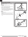
Power Components Service
B
A
C
F
J
I
H
G
E
D
K
O
L
M
N
CAUTION: Always disconnect the fl ight battery before performing motor service.
Disassembly
1. Remove the wing, disconnecting servos as needed.
2. Disconnect the motor connectors from the ESC connectors.
3. Remove the 2 screws (A) to remove the fan cover.
4. Remove the 2 screws (B) and fan unit (C) from the fuselage.
5. Remove the screw (D) and spinner (E) from the collet (F).
6. Remove the nut (G) rotor (H), washer (I) backplate (J) and collet from the motor.
You will need a tool to turn the nut. Tap lightly on the end of the collet to free the
backplate from the collet.
7. Remove 2 screws (K) and the motor (L) from the motor mount (M).
8. Remove 2 screws (N) and the housing (O) from the motor.
Assembly
• Assemble in reverse order.
• Correctly align and connect the motor wire colors with the ESC wires.
• Ensure the front of the rotor is installed facing the nose of the aircraft.
• A tool is required to tighten the nut on the rotor and collet.
• Ensure the spinner is fully connected for safe operation.
9

EN
Flying Tips and Repairs
Control Surface Direction
Consult local laws and ordinances before choosing a fl ying location.
Range Check your Radio System
Before you fl y, range check the radio system. Refer to your specifi c transmitter
instruction manual for range test information.
Rise Off Ground Takeoff
Place the aircraft in position for takeoff (facing into the wind). Select low rates
for fi rst takeoff and gradually increase the throttle to full and steer with the nose
wheel. Allow the model to accelerate to fl ying speed, then pull back gently on the
elevator and climb to a comfortable altitude.
Hand launch
It is advisable to have a helper for the fi rst few hand launches. Hold the airplane
behind the wing with the throwing hand and support the nose with the opposite hand.
Run the motor up to full throttle and give a FIRM throw straight ahead. The aircraft
should be launched fi rmly with the nose up 5–10 degrees and directly into the wind.
Flying
Always choose a wide-open space for fl ying. Due to the higher speeds of this
aircraft, it does require more room to fl y than average foam models. It is ideal
for you to fl y at a sanctioned fl ying fi eld. If you are not fl ying at an approved site,
always avoid fl ying near houses, trees, wires and buildings. You should also be
careful to avoid fl ying in areas where there are many people, such as busy parks,
schoolyards, or soccer fi elds.
In fl ight trimming
During your fi rst fl ight, trim the aircraft for level fl ight at 3/4 throttle. Make small
trim adjustments with your transmitter’s trim switches to straighten the aircraft’s
fl ight path. After landing, adjust the linkages mechanically to account for trim
changes and then reset the trims to neutral. Ensure the aircraft will fl y straight and
level with no trim or sub-trim.
Ailerons
Switch on the transmitter and connect the battery. Use the transmitter to operate
the ailerons. View the aircraft from the rear when checking the control directions.
1. Move the stick to the left. The right aileron will move down and the left aileron
move up, causing the aircrat to bank left.
2. Move the stick to the right. The right aileron will move up and the left aileron
move down, causing the aircraft to bank right.
Elevators
3. Move the stick toward the bottom of the transmitter. The elevators will move
up, causing the aircraft to climb.
4. Move the stick toward the top of the transmitter. The elevators will move
down, causing the aircraft to decend.
F-18 Blue Angel
10

EN
Flying Tips and Repairs (Continued)
WARNING:
Always
decrease throttle
before aircraft strike.
Post Flight
Low Voltage Cutoff (LVC)
When a Li-Po battery is discharged below 3V per cell, it will not hold a charge. The
ESC protects the fl ight battery from over-discharge using Low Voltage Cutoff (LVC).
Before the battery charge decreases too much, LVC removes power supplied to the
motor. Power to the motor pulses, showing that some battery power is reserved for
fl ight control and safe landing.
Disconnect and remove the Li-Po battery from the aircraft after use to prevent
trickle discharge. Charge your Li-Po battery to about half capacity before storage.
During storage, make sure the battery charge does not fall below 3V per cell. LVC
does not prevent the battery from over-discharge during storage.
NOTICE: Repeated fl ying to LVC will damage the battery.
Tip: Monitor your aircraft battery’s voltage before and after fl ying by using a Li-Po
Cell Voltage Checker (DYNF0002, sold separately).
Repairs
Thanks to the Z-Foam™ material in this aircraft, repairs to the foam can be made
using virtually any adhesive (hot glue, regular CA, epoxy, etc). When parts are not
repairable, see the Replacement Parts List for ordering by item number .
NOTICE: Use of CA accelerant on your aircraft can damage paint. DO NOT handle
the aircraft until accelerant fully dries.
Landing
For your fi rst fl ights with the recommended battery pack (KXSB0016), set your
transmitter timer or a stopwatch to 3 minutes. After three minutes, land the aircraft.
Adjust your timer for longer or shorter fl ights once you have fl own the model.
If at any time the motor pulses, land the aircraft immediately to recharge
the fl ight battery. See the Low Voltage Cutoff (LVC) section for more details on
maximizing battery health and run time.
Land the aircraft into the wind in a soft area, such as tall grass. Use a small amount
of throttle for the initial approach. Once the aircraft is on a proper approach angle and
the aircraft will land in the proper area, remove all throttle but maintain the descent.
During approach and landing, keep the wings level and the aircraft pointed into the
wind. As you approach 2-3 feet in altitude, begin your fl are. Continue easing back on
the elevator to bring the aircraft down gently on the belly.
NOTICE: If a crash is imminent, reduce the throttle and
trim fully. Failure to do so could result in extra damage to
the airframe, as well as damage to the ESC and motor.
NOTICE: After any impact, always ensure the receiver is
secure in the fuselage. If you replace the receiver, install
the new receiver in the same orientation as the original
receiver or damage may result.
NOTICE: Crash damage is not covered under warranty.
NOTICE: When you are fi nished fl ying, never leave the
aircraft in direct sunlight or in a hot, enclosed area such
as a car. Doing so can damage the aircraft.
1 Disconnect the fl ight battery from the ESC (Required for Safety and battery life).
2 Power OFF the transmitter.
3 Remove the fl ight battery from the aircraft.
4 Recharge the fl ight battery.
5 Repair or replace all damaged parts.
6 Store the fl ight battery apart from the aircraft and monitor the battery charge.
7
Make note of the fl ight conditions and fl ight plan results, planning for future fl ights.
11

EN
Problem Possible Cause Solution
Aircraft will not respond to
throttle but responds to other
controls
Throttle not at idle and/or throttle trim too high Reset controls with throttle stick and throttle trim at lowest setting
Throttle servo travel is lower than 100% Make sure throttle servo travel is 100% or greater
Throttle channel is reversed Reverse throttle channel on transmitter
Motor disconnected from ESC Make sure motor is connected to the ESC
Extra noise or extra vibration
during throttle operation
Damaged rotor, collet or motor Replace damaged parts
Rotor is out of balance Balance or replace rotor
Rotor nut is too loose Tighten the rotor nut
Reduced fl ight time or aircraft
underpowered
Flight battery charge is low Completely recharge fl ight battery
Flight battery damaged Replace fl ight battery and follow fl ight battery instructions
Flight conditions may be too cold Make sure battery is warm before use
Battery capacity too low for flight conditions Replace battery or use a larger capacity battery
Aircraft will not connect
(during binding) to transmitter
Transmitter too near aircraft during binding process Move powered transmitter a few feet from aircraft, disconnect and
reconnect fl ight battery to aircraft
Aircraft or transmitter is too close to large metal object, wire-
less source or another transmitter Move aircraft and transmitter to another location
and attempt binding again
The bind plug is not installed correctly in the bind port Install bind plug in bind port and bind the aircraft to the transmitter
Flight battery/transmitter battery charge is too low Replace/recharge batteries
Bind switch or button not held long enough during bind pro-
cess Power off transmitter and repeat bind process. Hold transmitter bind
button or switch until receiver is bound
Aircraft will not connect
(after binding) to transmitter
Transmitter too near aircraft during connecting process Move powered transmitter a few feet from aircraft, disconnect and
reconnect fl ight battery to aircraft
Aircraft or transmitter is too close to large metal object, wire-
less source or another transmitter Move aircraft and transmitter to another location and attempt con-
necting again
Bind plug left installed in bind port Rebind transmitter to the aircraft and remove the bind plug before
cycling power
Aircraft bound to different model memory
(ModelMatchTM radios only) Select correct model memory on transmitter
Flight battery/Transmitter battery charge is too low Replace/recharge batteries
Transmitter may have been bound to a different aircraft using
different DSM protocol Bind aircraft to transmitter
Control surface does not move
Control surface, control horn, linkage or servo damage Replace or repair damaged parts and adjust controls
Wire damaged or connections loose Do a check of wires and connections, connect or replace as needed
Transmitter is not bound correctly or the incorrect airplanes was
selected Re-bind or select correct airplanes in transmitter
Flight battery charge is low Fully recharge fl ight battery
BEC (Battery Elimination Circuit) of the ESC is damaged Replace ESC
Controls reversed Transmitter settings are reversed Perform the Control Direction Test and adjust the controls on the
transmitter appropriately
Motor power pulses then
motor loses power
ESC uses default soft Low Voltage Cutoff (LVC) Recharge fl ight battery or replace battery that is no longer performing
Weather conditions might be too cold Postpone flight until weather is warmer
Battery is old, worn out, or damaged Replace battery
Battery C rating might be too small Use recommended battery
Troubleshooting Guide
F-18 Blue Angel
12

EN
AMA National Model Aircraft Safety Code
Effective January 1, 2014
A. GENERAL
A model aircraft is a non-human-carrying aircraft capable of sustained fl ight in the
atmosphere. It may not exceed limitations of this code and is intended exclusively
for sport, recreation, education and/or competition. All model fl ights must be
conducted in accordance with this safety code and any additional rules specifi c to
the fl ying site.
1. Model aircraft will not be fl own:
(a) In a careless or reckless manner.
(b) At a location where model aircraft activities are prohibited.
2. M odel aircraft pilots will:
(a) Yield the right of way to all man carrying aircraft.
(b) See and avoid all aircraft and a spotter must be used when appropriate.
(AMA Document #540-D.)
(c) Not fl y higher than approximately 400 feet above ground level within three
(3) miles of an airport, without notifying the airport operator.
(d) Not interfere with operations and traffi c patterns at any airport, heliport or
seaplane base except where there is a mixed use agreement.
(e) Not exceed a takeoff weight, including fuel, of 55 pounds unless in
compliance with the AMA Large Model Aircraft program. (AMA Document
520-A.)
(f) Ensure the aircraft is identifi ed with the name and address or AMA number of
the owner on the inside or affi xed to the outside of the model aircraft. (This
does not apply to model aircraft fl own indoors).
(g) Not operate aircraft with metal-blade propellers or with gaseous boosts
except for helicopters operated under the provisions of AMA Document
#555.
(h) Not operate model aircraft while under the infl uence of alcohol or while
using any drug which could adversely affect the pilot’s ability to safely
control the model.
(i) Not operate model aircraft carrying pyrotechnic devices which explode
or burn, or any device which propels a projectile or drops any object that
creates a hazard to persons or property.
Exceptions:
• Free Flight fuses or devices that burn producing smoke and are securely
attached to the model aircraft during fl ight.
• Rocket motors (using solid propellant) up to a G-series size may be used
provided they remain attached to the model during fl ight. Model rockets
may be fl own in accordance with the National Model Rocketry Safety
Code but may not be launched from model aircraft.
• Offi cially designated AMA Air Show Teams (AST) are authorized to use
devices and practices as defi ned within the Team AMA Program Document
(AMA Document #718).
(j) Not operate a turbine-powered aircraft, unless in compliance with the AMA
turbine regulations. (AMA Document #510-A).
3. Model aircraft will not be fl own in AMA sanctioned events, air shows or model
demonstrations unless:
(a) The aircraft, control system and pilot skills have successfully demonstrated
all maneuvers intended or anticipated prior to the specifi c event.
(b) An inexperienced pilot is assisted by an experienced pilot.
4. When and where required by rule, helmets must be properly worn and fastened.
They must be OSHA, DOT, ANSI, SNELL or NOCSAE approved or comply with
comparable standards.
B. RADIO CONTROL
1. All pilots shall avoid fl ying directly over unprotected people, vessels, vehicles or
structures and shall avoid endangerment of life and property of others.
2. A successful radio equipment ground-range check in accordance with
manufacturer’s recommendations will be completed before the fi rst fl ight of a
new or repaired model aircraft.
3. At all fl ying sites a safety line(s) must be established in front of which all fl ying
takes place (AMA Document #706.)
(a) Only personnel associated with fl ying the model aircraft are allowed at or in
front of the safety line.
(b) At air shows or demonstrations, a straight safety line must be established.
(c) An area away from the safety line must be maintained for spectators.
(d) Intentional fl ying behind the safety line is prohibited.
4. RC model aircraft must use the radio-control frequencies currently allowed
by the Federal Communications Commission (FCC). Only individuals properly
licensed by the FCC are authorized to operate equipment on Amateur Band
frequencies.
5. RC model aircraft will not operate within three (3) miles of any pre-existing
fl ying site without a frequency-management agreement (AMA Documents #922
and #923.)
6. With the exception of events fl own under offi cial AMA Competition Regulations,
excluding takeoff and landing, no powered model may be fl own outdoors closer
than 25 feet to any individual, except for the pilot and the pilot’s helper(s)
located at the fl ight line.
7. Under no circumstances may a pilot or other person touch a model aircraft in
fl ight while it is still under power, except to divert it from striking an individual.
8. RC night fl ying requires a lighting system providing the pilot with a clear view of
the model’s attitude and orientation at all times. Hand-held illumination systems
are inadequate for night fl ying operations.
9. The pilot of a RC model aircraft shall:
(a) Maintain control during the entire fl ight, maintaining visual contact without
enhancement other than by corrective lenses prescribed for the pilot.
(b) Fly using the assistance of a camera or First-Person View (FPV) only in
accordance with the procedures outlined in AMA Document #550.
(c) Fly using the assistance of autopilot or stabilization system only in
accordance with the procedures outlined in AMA Document #560.
Please see your local or regional modeling association’s guidelines for proper,
safe operation of your model aircraft.
13

EN
Limited Warranty
Warranty and Service Contact Information
Country of Purchase Horizon Hobby Contact Information Address
North America
Horizon Service Center
(Repairs and Repair Requests) servicecenter.horizonhobby.com/RequestForm/
4105 Fieldstone Rd
Champaign, Illinois, 61822 USA
Horizon Product Support
(Product Technical Assistance)
productsupport@horizonhobby.com.
877-504-0233
Sales websales@horizonhobby.com
800-338-4639
What this Warranty Covers
Horizon Hobby, LLC, (Horizon) warrants to the original purchaser that the product
purchased (the “Product”) will be free from defects in materials and workmanship
at the date of purchase.
What is Not Covered
This warranty is not transferable and does not cover (i) cosmetic damage, (ii)
damage due to acts of God, accident, misuse, abuse, negligence, commercial use,
or due to improper use, installation, operation or maintenance, (iii) modifi cation of
or to any part of the Product, (iv) attempted service by anyone other than a Horizon
Hobby authorized service center, (v) Product not purchased from an authorized
Horizon dealer, (vi) Product not compliant with applicable technical regulations, or
(vii) use that violates any applicable laws, rules, or regulations.
OTHER THAN THE EXPRESS WARRANTY ABOVE, HORIZON MAKES NO OTHER
WARRANTY OR REPRESENTATION, AND HEREBY DISCLAIMS ANY AND ALL IMPLIED
WARRANTIES, INCLUDING, WITHOUT LIMITATION, THE IMPLIED WARRANTIES
OF NON-INFRINGEMENT, MERCHANTABILITY AND FITNESS FOR A PARTICULAR
PURPOSE. THE PURCHASER ACKNOWLEDGES THAT THEY ALONE HAVE
DETERMINED THAT THE PRODUCT WILL SUITABLY MEET THE REQUIREMENTS OF
THE PURCHASER’S INTENDED USE.
Purchaser’s Remedy
Horizon’s sole obligation and purchaser’s sole and exclusive remedy shall be that
Horizon will, at its option, either (i) service, or (ii) replace, any Product determined
by Horizon to be defective. Horizon reserves the right to inspect any and all
Product(s) involved in a warranty claim. Service or replacement decisions are
at the sole discretion of Horizon. Proof of purchase is required for all warranty
claims. SERVICE OR REPLACEMENT AS PROVIDED UNDER THIS WARRANTY IS THE
PURCHASER’S SOLE AND EXCLUSIVE REMEDY.
Limitation of Liability
HORIZON SHALL NOT BE LIABLE FOR SPECIAL, INDIRECT, INCIDENTAL OR
CONSEQUENTIAL DAMAGES, LOSS OF PROFITS OR PRODUCTION OR COMMERCIAL
LOSS IN ANY WAY, REGARDLESS OF WHETHER SUCH CLAIM IS BASED IN
CONTRACT, WARRANTY, TORT, NEGLIGENCE, STRICT LIABILITY OR ANY OTHER
THEORY OF LIABILITY, EVEN IF HORIZON HAS BEEN ADVISED OF THE POSSIBILITY
OF SUCH DAMAGES. Further, in no event shall the liability of Horizon exceed the
individual price of the Product on which liability is asserted. As Horizon has no
control over use, setup, fi nal assembly, modifi cation or misuse, no liability shall
be assumed nor accepted for any resulting damage or injury. By the act of use,
setup or assembly, the user accepts all resulting liability. If you as the purchaser
or user are not prepared to accept the liability associated with the use of the
Product, purchaser is advised to return the Product immediately in new and unused
condition to the place of purchase.
Law
These terms are governed by Illinois law (without regard to confl ict of law
principals). This warranty gives you specifi c legal rights, and you may also have
other rights which vary from state to state. Horizon reserves the right to change or
modify this warranty at any time without notice.
WARRANTY SERVICES
Questions, Assistance, and Services
Your local hobby store and/or place of purchase cannot provide warranty support
or service. Once assembly, setup or use of the Product has been started, you
must contact your local distributor or Horizon directly. This will enable Horizon
to better answer your questions and service you in the event that you may need
any assistance. For questions or assistance, please visit our website at www.
horizonhobby.com, submit a Product Support Inquiry, or call the toll free telephone
number referenced in the Warranty and Service Contact Information section to
speak with a Product Support representative.
Inspection or Services
If this Product needs to be inspected or serviced and is compliant in the country
you live and use the Product in, please use the Horizon Online Service Request
submission process found on our website or call Horizon to obtain a Return
Merchandise Authorization (RMA) number. Pack the Product securely using a
shipping carton. Please note that original boxes may be included, but are not
designed to withstand the rigors of shipping without additional protection. Ship
via a carrier that provides tracking and insurance for lost or damaged parcels,
as Horizon is not responsible for merchandise until it arrives and is accepted at
our facility. An Online Service Request is available at http://www.horizonhobby.
com/content/service-center_render-service-center. If you do not have internet
access, please contact Horizon Product Support to obtain a RMA number along
with instructions for submitting your product for service. When calling Horizon, you
will be asked to provide your complete name, street address, email address and
phone number where you can be reached during business hours. When sending
product into Horizon, please include your RMA number, a list of the included items,
and a brief summary of the problem. A copy of your original sales receipt must be
included for warranty consideration. Be sure your name, address, and RMA number
are clearly written on the outside of the shipping carton.
NOTICE: Do not ship LiPo batteries to Horizon. If you have any issue with a
LiPo battery, please contact the appropriate Horizon Product Support offi ce.
Warranty Requirements
For Warranty consideration, you must include your original sales receipt verifying
the proof-of-purchase date. Provided warranty conditions have been met, your
Product will be serviced or replaced free of charge. Service or replacement
decisions are at the sole discretion of Horizon.
Non-Warranty Service
Should your service not be covered by warranty, service will be completed and
payment will be required without notifi cation or estimate of the expense unless
the expense exceeds 50% of the retail purchase cost. By submitting the item for
service you are agreeing to payment of the service without notifi cation. Service
estimates are available upon request. You must include this request with your item
submitted for service. Non-warranty service estimates will be billed a minimum
of ½ hour of labor. In addition you will be billed for return freight. Horizon accepts
money orders and cashier’s checks, as well as Visa, MasterCard, American Express,
and Discover cards. By submitting any item to Horizon for service, you are agreeing
to Horizon’s Terms and Conditions found on our website http://www.horizonhobby.
com/content/service-center_render-service-center.
ATTENTION: Horizon service is limited to Product compliant in the country of
use and ownership. If received, a non-compliant Product will not be serviced.
Further, the sender will be responsible for arranging return shipment of the
un-serviced Product, through a carrier of the sender’s choice and at the
sender’s expense. Horizon will hold non-compliant Product for a period of 60
days from notifi cation, after which it will be discarded. 10/15
F-18 Blue Angel
14

FR
Précautions et avertissements liés à la sécurité
14+ 14 ans et plus. Ceci n’est pas un jouet.
REMARQUE
Toutes les instructions, garanties et autres documents de garantie sont sujets à la seule discrétion de Horizon Hobby, LLC. Veuillez, pour une littérature produits bien à
jour, visiter www.forcerc.com et cliquer sur l’onglet de support de ce produit.
MEANING OF SPECIAL LANGUAGE:
Les termes suivants servent, dans toute la documentation des produits, à désigner différents niveaux de blessures potentielles lors de l’utilisation de ce produit :
AVERTISSEMENT: Procédures qui, si elles ne sont pas correctement suivies, peuvent entraîner des dégâts matériels, dommages collatéraux et des blessures graves
éventuellement un décès OU créer un risque élevé de blessure superfi cielle.
ATTENTION: Procédures qui, si elles ne sont pas correctement suivies, peuvent entraîner des dégâts matériels ET éventuellement des blessures graves.
REMARQUE: Procédures qui, si elles ne sont pas correctement suivies, peuvent éventuellement entraîner des dégâts matériels ET créent un très faible risque de blessure.
AVERTISSEMENT : Lisez la TOTALITE du manuel d’utilisation afi n de vous familiariser avec les caractéristiques du produit avant de le faire fonctionner. Une
utilisation incorrecte du produit peut avoir comme résultat un endommagement du produit lui-même, des dégâts matériels voire entraîner des blessures graves.
Ceci est un produit de loisirs perfectionné. Il doit être manipulé avec prudence et bon sens et requiert quelques aptitudes de base à la mécanique. L’incapacité à manipuler
ce produit de manière sûre et responsable peut provoquer des blessures ou des dommages au produit ou à d’autres biens. Ce produit n’est pas destiné à être utilisé par
des enfants sans la supervision directe d’un adulte. N’essayez pas de modifi er ou d’utiliser ce produit avec des composants incompatibles hors des instructions fournies
par Horizon Hobby, LLC. Ce manuel comporte des instructions de sécurité, de mise en œuvre et d’entretien. Il est capital de lire et de respecter toutes les instructions et
avertissements du manuel avant l’assemblage, le réglage ou l’utilisation afi n de le manipuler correctement et d’éviter les dommages ou les blessures graves.
En tant qu’utilisateur de ce produit, il est de votre seule responsabilité de le faire fonctionner d’une manière qui ne mette en danger ni votre personne, ni de tiers et qui ne
provoque pas de dégâts au produit lui-même ou à la propriété d’autrui.
• Gardez une bonne distance de sécurité tout autour de votre modèle, afi n d’ éviter
les collisions ou les blessures. Ce modèle est contrôlé par un signal radio, qui peut
être soumis à des interférences provenant de nombreuses sources hors de votre
contrôle. Une interférence peut provoquer une perte momentanée de contrôle.
• Faites toujours fonctionner votre modèle dans une zone dégagée, à l’écart de
voitures, du trafi c et des personnes.
• Respectez toujours scrupuleusement les instructions et les mises en garde
concernant ce produit et tous les équipements optionnels/complémentaires
(chargeurs, packs de batteries rechargeables, etc.) que vous utilisez.
• Tenez tous les produits chimiques, les petites pièces et les composants
électroniques, hors de portée des enfants.
• Évitez toujours d’exposer à l’eau tout équipement non spécifi quement conçu et
protégé à cet effet. L’humidité endommage les composants électroniques.
• Ne léchez ni ne mettez jamais en bouche quelque partie de votre modèle que ce
soit - risque de blessures graves voire de danger de mort.
• Ne faites jamais fonctionner votre modèle lorsque les batteries de l’émetteur
sont faibles.
• Gardez toujours l’aéronef à vue et gardez-en toujours le contrôle.
• Utilisez toujours des batteries complètement chargées.
• Gardez toujours l’émetteur en marche lorsque l’aéronef est en marche.
• Enlevez toujours les batteries avant démontage.
• Veillez toujours à ce que les pièces en mouvement soient propres.
• Veillez toujours à ce que toutes les pièces soient sèches.
• Laissez toujours le temps aux pièces de refroidir avant de les toucher.
• Enlevez toujours les batteries après utilisation.
• Assurez-vous toujours que la sécurité (failsafe) est confi gurée correctement
avant de voler.
• Ne faites jamais voler un aéronef dont le câblage est endommagé.
• N’entrez jamais en contact avec des pièces en mouvement.
15

FR
Contenu de la boîte
Table des Matières
660g
Caractéristiques
12.3 sq dm
Précautions et avertissements liés à la sécurité .................................................. 15
Contenu de la boîte ............................................................................................. 16
Caractéristiques .................................................................................................. 16
Table des Matières .............................................................................................. 16
Liste des opérations à effectuer avant le vol ....................................................... 17
Assemblage du modèle ....................................................................................... 17
Version PNP Choix et installation du récepteur .................................................... 20
Installation de la batterie et armement du contrôleur .......................................... 20
Centre de gravité (CG) ......................................................................................... 20
Installation des manilles et centrage des commandes ......................................... 21
Réglages aux guignols et au bras de servos ........................................................ 21
Réparation des pièces électriques ....................................................................... 22
Direction des gouvernes ..................................................................................... 23
Conseils de vol et réparations ............................................................................. 23
Maintenance d’après vol ..................................................................................... 24
Guide de dépannage ........................................................................................... 25
Garantie Limitée ................................................................................................. 26
Coordonnées de service et de garantie ............................................................... 26
Pièces de rechange ............................................................................................ 27
Guide de démarrage rapide
Paramètres
émetteur
1. Programme avion vierge
2. Direction des servos : Normal
3. Courses (toutes les gouvernes) : 100%
Double-
débattements
Lancer main et
atterrissage Petits
Ail =14mm
=14mm
=10mm
=10mm
Prof =12mm
=12mm
=8mm
=8mm
EXPO
(Soft center)
Grand Petits
Ail 15% 5%
Prof 20% 5%
Centre de
gravité 80–85mm en arrière du bord d’attaque au
niveau de l’emplanture de l’aile
Réglage
chronomètre 3 minutes
Moteur: Moteur sans balais Outrunner: KV3150 (FMMKV3150)
Installé
Contrôleur: ESC 40A Switch Mode sans balais (FMMPAC113)
Installé
(5) servos
(FMMSER9GP, FMMSER9G54, FMMSER9GR) Installés
Récepteur recommandé: Spektrum AR636A 6 voies Requis
Batterie recommandée: Li-Po 4S 14,8V 2400mAh
30C (KXSB0016) Requise
Chargeur de batterie recommandé:
Charge et équilibrages des batterie LI-Po 4S Requis
Emetteur recommandé: Équipé de la technologie
Spektrum 2.4GHz DSM2/DSMX (DX6i ou supérieur) Requis
675mm
960mm
F-18 Blue Angel
16

FR
Assemblage du modèle
A
B
Liste des opérations à effectuer avant le vol
1 Retirez les éléments de la boîte et inspectez-les.
2 Lisez attentivement le présent manuel d’utilisation.
3 Chargez la batterie de vol.
4 Assemblez le modèle complètement.
5 Installez la batterie dans le modèle (Une fois la charge terminée).
6 Vérifi ez la position du centre de gravité (CG).
7 Affectez votre émetteur au modèle.
8 Contrôlez le mouvement des tringleries de commande.
9 Vérifi ez que les tringleries bougent librement.
10 Effectuez un essai de la réponse de l’AS3X.
11 Réglez les tringleries et l’émetteur.
12 Effecuez un essai de portée radio.
13 Trouvez un lieu dégagé et sûr.
14 Plannifi ez votre vol en fonction des conditions du terrain.
Installation des ailes
1. Glissez le tube d’aile dans le fuselage.
2. Glissez les panneaux d’aile (A) sur le tube d’aile. Assurez-vous que les
panneaux d’aile sont bien serrés contre le fuselage.
3. Installez 4 vis (B) pour fi xer les panneaux d’aile principaux à leur place.
4. Fixez la manille au guignol de contrôle de l’aileron (voir les instructions
pour le raccordement de la manille).
5. Le cas échéant, démontez-le dans l’ordre inverse.
3mm X 10mm
17

FR
Assemblage du modèle (Suite)
Installation du stabilisateur horizontal
1. Appliquez de la colle cyanoacrylate sur la base du stabilisateur horizontal
qui s’insérera dans le fuselage.
2. Appliquez de la colle cyanoacrylate dans le fuselage au niveau de la fente
du stabilisateur horizontal.
3. Insérez le stabilisateur horizontal dans la fente. Assurez-vous que le guignol
de contrôle est orienté vers le bas du fuselage.
Assurez-vous que le stabilisateur horizontal est aligné avec l’aile. Ajustez si
nécessaire avant que la colle cyanoacrylate ne soit complètement sèche.
Installation du stabilisateur vertical
1. Appliquez de la colle cyanoacrylate sur la base du stabilisateur vertical qui
s’insérera dans le fuselage.
2. Appliquez de la colle cyanoacrylate dans le fuselage au niveau de la fente
du stabilisateur vertical.
3. Insérez le stabilisateur vertical dans la fente.
Assurez-vous que le stabilisateur vertical est incliné vers l’extérieur, comme
illustré. Assurez-vous également que l’inclinaison des deux stabilisateurs
verticaux est la même.
Installation de la manille
1. Fixez les manilles aux guignols de contrôle. Pour plus d’informations,
référez-vous aux pages suivantes.
F-18 Blue Angel
18

FR
Assemblage du modèle (Suite)
Installation du train d’atterrissage
1. Installez (4) vis pour fi xer le train d’atterrissage.
Installation des missiles
1. Utilisez de la colle cyanoacrylate pour fi xer les missiles à l’appareil.
Consultez l’illustration pour l’emplacement correct de chaque objet.
Installation du cône de nez
1. Appliquez de la colle cyanoacrylate dans le fuselage au niveau du logement
du cône de nez. Assurez-vous que le cône de nez est orienté correctement.
2mm X 8mm
19

FR
Le récepteur Spektrum AR636A est recommandé pour cet avion. Si vous désirez
utiliser un autre récepteur, il devra avoir 4 voies au minimum et avoir une longue
portée. Référez-vous au manuel de votre récepteur pour consulter les instructions
relatives à son installation et son utilisation.
Installation (AR636 représenté)
1. Retirez la trappe du fuselage.
2. Installez le récepteur à la parallèle à la longueur du fuselage comme sur
l’illustration. Utilisez de l’adhésif double-face.
ATTENTION: Une installation incorrecte du récepteur peut entraîner
un crash.
3. Connectez les servos des gouvernes à leurs ports respectifs en utilisant le
tableau de référence.
Version PNP Choix et installation du récepteur
1 = Gaz
2 = Ailerons
3 = Profondeur
4 = Direction
de roue avant
Installation de la batterie et armement du contrôleur
A
B
C
B
Centre de gravité (CG)
80-85mm
en arrière du bord d’attaque au niveau de l’emplanture de l’aile.
Choix de la batterie
Nous recommandons la batterie Li-Po 2400 mAh 14,8 V 4S 30C: EC3 Kinexsis
(KXSB0016) pour le fonctionnement standard. Si vous utilisez une batterie différente, la
batterie devrait avoir une capacité, des dimensions et un poids similaires de la batterie
Kinexsis Li-Po pour s’adapter au fuselage. Assurez-vous que la maquette est équilibrée au
CG recommandé.
1. Baissez le manche et le trim des gaz aux niveaux les plus bas. Allumez
l’émetteur, puis attendez 5 secondes.
2. Appliquez le côté bouclettes (côté doux) du ruban à bouclettes (A) sur le bas
de votre batterie.
3. Soulevez soigneusement l’arrière de la trappe de verrière (B) pour la retirer.
4. Installez la batterie entièrement chargée dans le compartiment de batterie
comme illustré. Pour plus d’informations, consultez les Instructions
d’ajustement du centre de gravité.
5. Assurez-vous que la batterie de vol est bien fi xée.
6. Raccordez la batterie au variateur (C) (celui-ci est maintenant armé).
7. Maintenez l’appareil immobile et à l’abri du vent, ou le système ne démarrera
pas.
• Le variateur émettra une série de sons (consultez l’étape 6 des instructions de
couplage pour plus d’informations).
• Une DEL s’allumera sur le récepteur.
Si le variateur émet un double bip continu après que la batterie de vol a été
connectée, rechargez ou remplacez la batterie.
8. Réinstallez la trappe de la verrière.
L’emplacement du CG est mesuré à partir du bord d’attaque de l’aile, à la base.
L’emplacement du CG a été déterminé avec la batterie Li-Po recommandée
installée entièrement vers l’avant dans le compartiment de la batterie.
F-18 Blue Angel
20
La page est en cours de chargement...
La page est en cours de chargement...
La page est en cours de chargement...
La page est en cours de chargement...
La page est en cours de chargement...
La page est en cours de chargement...
La page est en cours de chargement...
La page est en cours de chargement...
-
 1
1
-
 2
2
-
 3
3
-
 4
4
-
 5
5
-
 6
6
-
 7
7
-
 8
8
-
 9
9
-
 10
10
-
 11
11
-
 12
12
-
 13
13
-
 14
14
-
 15
15
-
 16
16
-
 17
17
-
 18
18
-
 19
19
-
 20
20
-
 21
21
-
 22
22
-
 23
23
-
 24
24
-
 25
25
-
 26
26
-
 27
27
-
 28
28


Force RC FCEF060001 Le manuel du propriétaire
- Catégorie
- Jouets télécommandés
- Taper
- Le manuel du propriétaire
dans d''autres langues
- English: Force RC FCEF060001 Owner's manual