Cat Pumps CT80020 Mode d'emploi
- Catégorie
- Nettoyeurs haute pression
- Taper
- Mode d'emploi

SAVE THIS MANUAL FOR FUTURE REFERENCE
Ce nettoyeur haute pression a été conçu et fabriqué conformément
aux strictes normes de fiabilité, simplicité d’emploi et sécurité
d’utilisation. Correctement entretenu, il vous donnera des années
de fonctionnement robuste et sans problème.
AVERTISSEMENT :
Pour réduire les risques de
blessures, l’utilisateur doit lire et veiller à bien comprendre
le manuel d’utilisation avant d’utiliser ce produit.
Merci de votre achat.
Su lavadora de presión ha sido diseñada y fabricada
de conformidad con las estrictas normas para brindar
fiabilidad, facilidad de uso y seguridad para el operador. Con el
debido cuidado, le brindará muchos años de sólido y eficiente
funcionamiento.
ADVERTENCIA: Para reducir el riesgo de lesiones, el
usuario debe leer y comprender el manual del operador antes
de usar este producto.
Le agradecemos su compra.
CONSERVER CE MANUEL POUR
FUTURE RÉFÉRENCE GUARDE ESTE MANUAL PARA
FUTURAS CONSULTAS
Your pressure washer has been engineered and manufactured to our high standard for dependability, ease of operation,
and operator safety. When properly cared for, it will give you years of rugged, trouble-free performance.
WARNING: To reduce the risk of injury, the user must read and understand the operator’s manual before using
this product.
Thank you for your purchase.
OPERATOR’S MANUAL
MANUEL D’UTILISATION
MANUAL DEL OPERADOR
3800 PSI PRESSURE WASHER
NETTOYEUR HAUTE PRESSION
DE 3 800 PSI
LAVADORA A PRESIÓN
DE 3 800 PSI
CT80020
To register your pressure
washer, please visit:
http://bluepowersite.com/
Pour enregistrer votre laveuse à
pression, s’il vous plaît la visite:
http://bluepowersite.com/
Para registrar su lavadora de
presión, por favor visita:
http://bluepowersite.com/

ii
See this fold-out section for all of the figures
referenced in the operator’s manual.
Consulter l’encart à volets afin d’examiner
toutes les figures mentionnées dans le manuel
d’utilisation.
Consulte esta sección desplegable para ver
todas las figuras a las que se hace referencia en
el manual del operador.

iii
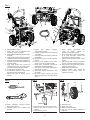
Fig. 1
Fig. 3
Fig. 2
A -Phillips screwdriver (tournevis phillips,
destornillador phillips)
B - Adjustable wrench (clé a molette, llave
ajustable)
Fig. 4
B
A
A
A - Lock nut (écrou de blocage, contratuerca)
B - Support foot (pied de support, pie de
soporte)
C - Bolts (boulons, pernos)
A - Axle (essieu, eje)
B - Wheel (roue, rueda)
C - Washer (rondelle, arandela)
D - Hitch pin (axe de blocage, pasador de
enganche)
B
C
A
B
C
D
A - Handle (poignèe, mango)
B - Trigger with lock out (gâchette avec
verrouillage, gatillo con seguro)
C - Trigger handle (poignée de gâchette, mango
del gatillo)
D - Trigger handle holder (support de la poignée
à gâchette, soporte del mango del gatillo)
E - Trigger handle storage hook (rangement de
la poignée à gâchette, almacenamiento del
mango del gatillo)
F - Spray wand storage hook (crochet de
rangement de la lance d’arrosage, gancho
para almacenamiento del tubo rociador)
G - Air filter (filtre à air, filtro de aire)
H - Oil cap/dipstick (bouchon / jauge d’huile,
tapa del aceite con varilla de nivel)
I - Support foot (pied de support, pie de
soporte)
J - Injection hose (flexible d’injection,
manguera de inyección)
K - Fuel tank (réservoir de carburant, tanque de
combustible)
L - Fuel valve (robinet de carburant, válvula de
combustible)
M - Recoil starter (lanceur à rappel, arrancador
retráctil)
N - Low oil sensor (détecteur de bas niveau
d’huile, sensor de nivel bajo de aceite)
O - On/off switch (interrupteur marche/arrêt,
interruptor de encendido/apagado)
P - Soap Blaster™ nozzle (buse Soap Blaster™,
Soap Blaster™ boquilla)
Q - Spray wand (lance de pulvérisation , tubo
de rociado)
R - Idle down cylinder (cylindre de ralenti,
cilindro de disminución de la velocidad de
ralentí)
S - Nozzle storage (porte-buses avec
ressort de support, sujetador de
boquillas con resorte de soporte)
T - Spray wand holder (crochet de rangement
de la lance d’arrosage, gancho para
almacenamiento del tubo rociador)
U - Auxiliary handle (poignée auxiliaire, mango
auxiliar)
V - Hose storage hook (crochet de rangement
du tuyau, crochet de rangement du tuyau)
W - High pressure hose (tuyau haute pression,
manguera de alta presión)
Y - Muffler (silencieux, silenciador)
Z - Pressure regulator knob (bouton de
régulation de la pression, perilla del
regulador de presión)
N
K
A
V
B
C
Q
R
I
P
W
U
Y
J
E
D
T
M
G
L
O
H
S
Z
F

iv
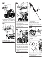
Fig. 6
Fig. 7
Fig. 5
Fig. 8
Fig. 9
A - Trigger handle (poignée de gâchette,
mango del gatillo)
B - Auxiliary handle (poignée auxiliaire,
mango auxiliar)
C - Connector (connecteur, conector)
D - Spray wand (lance de pulvérisation, tubo
rociador)
A - Handle release knob (bouton de dégagement
de la poignée, perilla de liberación del
mango)
B - Handle (poignèe, mango)
AB
C
D
BA
C
Fig. 10
A - High pressure hose (tuyau haute pression,
manguera de alta presión)
B - Collar (collier, collarín)
C - Inlet coupler (raccord d’entrée, acoplador
de entrada)
Fig. 11
A - Injection hose with filter (flexible d’injection
avec filtre, manguera de inyección con filtro)
B - Detergent bottle (bouteille de détergente,
botella del detergente)
A
A - Screw (vis, tornillo)
B - Rear panel (panneau arrière, panel posterior)
C - Handle (poignèe, mango)
D - Lock nut (écrou de blocage, contratuerca)
A - Trigger handle holder (support de la poignée
à gâchette, soporte del mango del gatillo)
B - Lock nut (écrou de blocage, contratuerca)
C - Handle (poignèe, mango)
D - Trigger handle storage hook (rangement de
la poignée à gâchette, almacenamiento del
mango del gatillo)
E - Frame (cadre, armazón)
A - Trigger handle storage hook (rangement de
la poignée à gâchette, almacenamiento del
mango del gatillo)
B - Spray wand storage hook (crochet de
rangement de la lance d’arrosage, gancho
para almacenamiento del tubo rociador)
C - Frame (cadre, armazón)
D - Rubber grommet (oeillet en caoutchouc, ojal
de goma)
E - Lock nut (écrou de blocage, contratuerca)
B
ABC
D
AB
C
E
D
B
A
B
DE
C
A
B

v
A - Oil cap/dipstick (bouchon / jauge d’huile,
tapa del aceite con varilla de nivel)
B - Funnel (entonnoir, embudo)
Fig. 14
Fig. 15
A - Funnel (entonnoir, embudo)
B - Fuel cap (bouchon de carburant, tapa del
tanque de combustible)
Fig. 16
A - On/off switch (interrupteur marche/arrêt,
interruptor de encendido/apagado)
A - Recoil starter (lanceur à rappel, arrancador
retráctil)
Fig. 18
Fig. 19
A - Slot (encoche, ranura)
B - Lock out (verrouillage, seguro)
C - Trigger (gâchette, gatillo)
Fig. 13
A - High pressure hose (tuyau haute pression,
manguera de alta presión)
B - Inlet coupler (raccord d’entrée, acoplador
de entrada)
C - Collar (collier, collarín)
Fig. 12
A - Garden hose (tuyau d’arrosage, manguera
de jardín)
B - Screen (tamis, cedazo)
C - Water intake (prise d’eau, entrada de agua)
Fig. 20
A - Spray wand (lance de pulvérisation, tubo
rociador)
B - Quick-connect collar (collier de raccord
rapide, casquillo de conexión rápida)
C - Soap Blaster™ nozzle (buse Soap Blaster™,
Soap Blaster™ boquilla)
D - Short range detergent application
(application détergente court de gamme,
aplicación de detergente corto plazo)
E - Long range detergent application
(application détergente long de gamme,
aplicación de detergente largo plazo)
F - Nozzle (buse, boquilla)
A
DB
C
F
E
B
A
C
A
B
A
C
B
A
A
B
A
B
C
OFF
ON
A
Fig. 17
A - Choke lever (levier de volet de départ,
palanca del anegador)
B - Fuel valve (robinet de carburant, válvula de
combustible)
A
B

vi
Fig. 21
Fig. 22
Fig. 23
A - Long range (long de gamme, largo plazo) B - Short range (short de gamme, corto plazo)
TO MOVE THE MACHINE
(POUR DÉPLACER
L’ÉQUIPEMENT, PARA
MOVER LA MÁQUINA)
Fig. 24
Fig. 28
A - Oil drain plug (bouchon de vidange
d’huile, tapón de drenaje del aceite)
B - Container (récipient, recipiente)
Fig. 27
A - 0.028 in. - 0.032 in.
[0,7 - 0,8 mm (0,028 po - 0,032 po),
0,7 - 0,8 mm (0,028 pulg. - 0,032 pulg.)]
A
B
A
A
B
Fig. 26
A - Screw (vis, tornillo)
B - Air filter cover (couvercle du filtre à air,
tapa del filtro de aire)
C - Air filter (filtre à air, filtro de aire)
A
B
C
Fig. 25
A - Paper clip (pièces de papier, clips de papel)
B - Nozzle (buse, boquilla)
AB
C
BA
A - To increase pressure (pour augmenter la
pression, para aumentar la presión)
B - To decrease pressure (pour réduire la
pression, para disminuir la presión)
C - Pressure regulator knob (bouton de
régulation de la pression, perilla del
regulador de presión)

vii
Fig. 30 Fig. 31
A - Fuel tank inlet screen (grillage d’admission
du réservoir de carburant, filtro de entrada
del tanque de combustible)
B - Tank filler neck (goulot de remplissage du
réservoir, boca del depósito)
A
B
Fig. 29
A - Sight glass (voyant d’huile, visor)
B - Pump oil vent cap (bouchon du réservoir
d’huile de la pompe, tapa de aceite de la
bomba)
C - Container (conteneur, recipiente)
D - Oil drain plug (bouchon huile, tapón de
drenaje del aceite)
B
CD
A

Page 2 — English
Introduction ......................................................................................................................................................................2
Introduction / Introducción
Important Safety Instructions ........................................................................................................................................... 3
Instructions importantes concernant la sécurité / Instrucciones de seguridad importantes
Specific Safety Rules ........................................................................................................................................................ 4
Règles de sécurité particulières / Reglas de seguridad específicas
Symbols ......................................................................................................................................................................... 5-6
Symboles / Símbolos
Features ............................................................................................................................................................................7
Caractéristiques / Características
Assembly .....................................................................................................................................................................8-10
Assemblage / Armado
Operation ................................................................................................................................................................... 11-14
Utilisation / Funcionamiento
Maintenance ..............................................................................................................................................................15-17
Entretien / Mantenimiento
Troubleshooting .............................................................................................................................................................. 18
Dépannage / Solución de problemas
Warranty ....................................................................................................................................................................19-20
Garantie / Garantía
Parts Ordering and Service ...............................................................................................................................Back Page
Commande de pièces et réparation / Pedidos de piezas y servicio ..................................... Page arrière / Pág. posterior
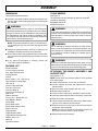
This product has many features for making its use more pleasant and enjoyable. Safety, performance, and dependability
have been given top priority in the design of this product making it easy to maintain and operate.
* * *
Ce produit offre de nombreuses fonctions destinées à rendre son utilisation plus plaisante et satisfaisante. Lors de la
conception de ce produit, l’accent a été mis sur la sécurité, les performances et la fiabilité, afin d’en faire un outil facile à
utiliser et à entretenir.
* * *
Este producto ofrece numerosas características para hacer más agradable y placentero su uso. En el diseño de este producto
se ha conferido prioridad a la seguridad, el desempeño y la fiabilidad, por lo cual se facilita su manejo y mantenimiento.
TABLE OF CONTENTS
TABLE DES MATIÈRES / ÍNDICE DE CONTENIDO
INTRODUCTION
INTRODUCTION / INTRODUCCIÓN

Page 3 — English
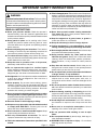
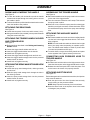
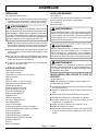
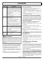
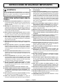
IMPORTANT SAFETY INSTRUCTIONS
WARNING:
Read and understand all instructions. Failure to follow
all instructions listed below may result in electric shock,
fire and/or carbon monoxide poisoning which will cause
death or serious personal injury.
READ ALL INSTRUCTIONS
Know your pressure washer. Read the operator’s
manual carefully. Learn the machine’s applications and
limitations as well as the specific potential hazards related
to this pressure washer.
Keep guards in place and in working order. Never
operate the pressure washer with any guard or cover
removed. Make sure all guards are operating properly
before each use.
Remove adjusting keys and wrenches. Form habit of
checking to see that keys and adjusting wrenches are
removed from pressure washer before turning it on.
To reduce the risk of injury, keep children and visitors
away. All visitors should wear safety glasses and be kept
a safe distance from work area.
Keep the area of operation clear of all persons,
particularly small children, and pets.
Do not operate the engine in a confined space
where dangerous carbon monoxide fumes can collect.
Carbon monoxide, a colorless, odorless, and extremely
dangerous gas, can cause unconsciousness or death.
Use right tool. Don’t force pressure washer or attachment
to do a job it was not designed for. Don’t use it for a
purpose not intended.
Dress properly. Do not wear loose clothing, gloves,
neckties, or jewelry. They can get caught and draw you
into moving parts. Rubber gloves and nonskid footwear
are recommended when working outdoors. Also wear
protective hair covering to contain long hair.
Do not operate the equipment while barefoot or when
wearing sandals or similar lightweight footwear. Wear
protective footwear that will protect your feet and improve
your footing on slippery surfaces.
Exercise caution to avoid slipping or falling.
Always wear eye protection with side shields marked
to comply with ANSI Z87.1. Following this rule will
reduce the risk of serious personal injury.
Don’t overreach or stand on unstable support. Keep
proper footing and balance at all times.
Use only recommended accessories. The use of
improper accessories may cause risk of injury.
Follow the maintenance instructions specified in this
manual.
Check damaged parts. Before further use of the
pressure
washer, a guard or other part that is damaged should be
carefully checked to determine that it will operate properly
and perform its intended function. Check for alignment of
moving parts, binding of moving parts, breakage of parts,
mounting, and any other conditions that may affect its
operation. A guard or other part that is damaged must
be properly repaired or replaced by an authorized service
center to avoid risk of personal injury.
Never leave pressure washer running unattended.
Turn power off. Don’t leave pressure washer until it
comes to a complete stop.
Keep the engine free of grass, leaves, or grease to
reduce the chance of a fire hazard.
Keep the exhaust pipe free of foreign objects.
Follow manufacturer’s recommendations for safe
loading, unloading, transport, and storage of machine.
Be thoroughly familiar with controls. Know how to stop
the product and bleed pressure quickly.
Keep pressure washer dry, clean, and free from
lubricant and grease. Always use a clean cloth when
cleaning. Never use brake fluids, gasoline, petroleum-
based products, or any solvents to clean pressure
washer.
Stay alert and exercise control. Watch what you are
doing and use common sense. Do not operate pressure
washer when you are tired. Do not rush.
Do not operate the product while under the influence
of drugs, alcohol, or any medication.
Check the work area before each use. Remove all
objects such as rocks, broken glass, nails, wire, or
string which can be thrown or become entangled in the
machine.
Do not use pressure washer if switch does not turn it
off. Have defective switches replaced by an authorized
service center.
Before cleaning, repairing, or inspecting, shut off the
engine and make certain all moving parts have stopped.
Disconnect the spark plug wire, and keep the wire away
from the plug to prevent accidental starting.
Avoid dangerous environment. Don’t use in damp or
wet locations or expose to rain. Keep work area well
lit.
Never use in an explosive atmosphere. Normal
sparking of the motor could ignite fumes.
Do not operature while smoking or near an open
flame.
Do not operate around dry brush, twigs, cloth rags, or
other flammable materials.
WARNING: Risk of injection or injury – Do not direct
discharge stream at persons.

Page 4 — English
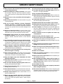
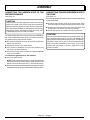
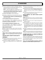
SPECIFIC SAFETY RULES
Never direct a water stream toward people or pets,
or any electrical device.
Before starting any cleaning operation, close doors
and windows. Clear the area to be cleaned of debris,
toys, outdoor furniture, or other objects that could create
a hazard.
Never pick up or carry a machine while the engine is
running.
Never start the machine if ice has formed in any part
of the equipment.
Do not use acids, alkalines, solvents, flammable
material, bleaches, or industrial grade solutions
in this product. These products can cause physical
injuries to the operator and irreversible damage to the
machine.
Always operate the machine on a level surface. If the
engine is on an incline, it could seize due to improper
lubrication (even at the maximum lubricant level).
WARNING: High pressure jets can be dangerous
if subject to misuse. The jet must not be directed at
persons, animals, electrical devices, or the machine
itself.
Hold the handles and wand securely with both hands.
Expect the trigger handle to kickback when the trigger
is pulled due to reaction forces. Failure to do so could
cause loss of control and injury to yourself and others.
Never attempt to make any adjustments while the
engine (motor) is running (except where specifically
recommended by the manufacturer).
Protective covers must always cover rotating parts
when the engine is running.
Keep cooling air intake (recoil starter area) and muffler
side of the engine at least 3 feet away from buildings,
obstructions, and other combustible objects.
Keep the engine away from flammables and other
hazardous materials.
Keep away from hot parts. The muffler and other engine
parts become very hot; use caution.
Do not touch the spark plug and ignition cable when
starting and operating the engine.
Check fuel hoses and joints for looseness and fuel
leakage before each use.
Check bolts and nuts for looseness before each use.
A loose bolt or nut may cause serious engine problems.
Always refuel outdoors. Never refuel indoors or in a
poorly ventilated area.
Never store the machine with fuel in the fuel tank
inside a building where ignition sources are present,
such as hot water and space heaters, clothes dryers,
and the like.
If the fuel tank has to be drained, do this outdoors.
To reduce the risk of fire and burn injury, handle fuel
with care. It is highly flammable.
Do not smoke while handling fuel.
Add fuel before starting the engine. Never remove the
cap of the fuel tank or add fuel while the engine is running
or when the engine is hot.
Loosen fuel cap slowly to release pressure and to keep
fuel from escaping around the cap.
Replace all fuel tank and container caps securely.
Wipe spilled fuel from the pressure washer. Move 30
feet away from refueling site before starting engine.
If fuel is spilled, do not attempt to start the engine but
move the machine away from the area of spillage and
avoid creating any source of ignition until fuel vapors
have dissipated.
Never attempt to burn off spilled fuel under any
circumstances.
Before storing, allow the engine to cool.
Store fuel in a cool, well-ventilated area, safely away
from spark and/or flame-producing equipment.
Store fuel in containers specifically designed for this
purpose.
Empty fuel tank and restrain the pressure washer from
moving before transporting in a vehicle.
When servicing use only identical replacement parts.
Use of any other parts may create a hazard or cause
product damage.
ONLY use cold water.
Make sure minimum clearance of 3 feet is maintained
from combustible materials.
Never spray close to the surface to be cleaned as you
can damage the surface.
After stopping the engine, always pull the trigger on
the trigger handle to relieve stored pressure in the
high pressure hose. Failure to do so could result in
serious personal injury.
For outdoor use only.
Ensure the high pressure hose is properly connected
before using the product.
Save these instructions. Refer to them frequently and
use them to instruct other users. If you loan someone this
pressure washer, loan them these instructions also.

Page 5 — English
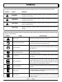
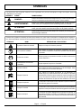
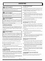
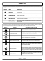
SYMBOLS
Some of the following symbols may be used on this product. Please study them and learn their meaning for safe
operation of this product.
SYMBOL NAME EXPLANATION
Safety Alert Indicates a potential personal injury hazard.
Read Operator’s Manual To reduce the risk of injury, user must read and understand
operator’s manual before using this product.
Eye Protection Always wear eye protection with side shields marked to comply
with ANSI Z87.1.
Wet Conditions Alert Do not expose to rain or use in damp locations or spray directly
on the pressure washer.
Hot Surface To reduce the risk of injury or damage, avoid contact with any
hot surface.
Risk of Injections
To reduce the risk of injection or injury, never direct a water
stream towards people or pets or place any body part in the
stream. Leaking hoses and fittings are also capable of causing
injection injury. Do not hold hoses or fittings.
Risk of Explosion Fuel and its vapors are explosive and can cause severe burns
or death.
Risk of Fire Fuel and its vapors are extremely flammable and explosive. Fire
can cause severe burns or death.
Toxic Fumes
Gas products emit carbon monoxide, an odorless, colorless,
poison gas. Breathing carbon monoxide can cause nausea,
fainting, or death.
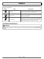
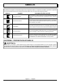
The following signal words and meanings are intended to explain the levels of risk associated with this product.
SYMBOL SIGNAL MEANING
DANGER: Indicates an imminently hazardous situation, which, if not avoided, will result
in death or serious injury.
WARNING: Indicates a potentially hazardous situation, which, if not avoided, could result
in death or serious injury.
CAUTION: Indicates a potentially hazardous situation, which, if not avoided, may result in
minor or moderate injury.
CAUTION: (Without Safety Alert Symbol) Indicates a situation that may result in property
damage.

Page 6 — English
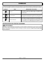
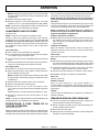
SYMBOLS
Some of the following symbols may be used on this product. Please study them and learn their meaning for safe
operation of this product.
SYMBOL NAME EXPLANATION
Kickback To reduce the risk of injury from kickback, hold the spray wand
securely with both hands when the machine is on.
Electric Shock Failure to use in dry conditions and to observe safe practices
can result in electric shock.
Chemical Burns
To reduce the risk of injury or damage, DO NOT USE ACIDS,
ALKALINES, BLEACHES, SOLVENTS, FLAMMABLE MATERIAL,
OR INDUSTRIAL GRADE SOLUTIONS in this product.
WARNING:
This product, its exhaust, and other substances that may become airborne from its use may contain chemicals, includ-
ing lead, known to the State of California to cause cancer, birth defects, or other reproductive harm. Wash hands after
handling
CALIFORNIA PROPOSITION 65

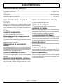
Page 7 — English
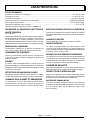
FEATURES
PRODUCT SPECIFICATIONS
Fuel Tank Capacity ....................................................................................................................................................... 1.8 gal
Engine Oil Capacity .................................................................................................................................................... 37.2 oz.
Pump Oil Capacity .....................................................................................................................................................10.5 oz.
Maximum Pounds Per Square Inch Pressure* .........................................................................................................3,800 psi
Maximum Gallons Per Minute* ...................................................................................................................................3.5 gpm
Maximum Inlet Water Temperature ................................................................................................................................104˚F
*Max. rating determined by PWMA Standard 101
KNOW YOUR PRESSURE WASHER
See Figure 1.
The safe use of this product requires an understanding of
the information on the pressure washer and in this operator’s
manual as well as a knowledge of the project you are
attempting. Before use of this product, familiarize yourself
with all operating features and safety rules.
FUEL TANK
This fuel tank has a maximum capacity of 1.8 gal. Use
unleaded automotive gasoline in the engine.
HOSE STORAGE
Once the high pressure hose is rolled, hang it on the back
of the machine using the stretch strap to secure in place.
IDLE DOWN
The engine idle speed is automatically reduced when the
trigger is released. This feature increases fuel efficiency,
reduces the noise level, and decreases wear and tear over
the life of the pressure washer.
LOW OIL SENSOR
The low oil sensor will light and the engine will automatically
shut off whenever the lubricant level in the engine becomes
low.
ON/OFF SWITCH
The on/off switch is used in combination with the recoil starter
to start the engine. It is also used to turn the engine off.
PRESSURE REGULATOR KNOB
The pressure regulator knob regulates the outgoing pressure
from the pump to the high pressure hose.
RECOIL STARTER
The recoil starter is pulled to start the machine.
SPARK ARRESTOR
This engine is not factory equipped with a spark arrestor.
In some areas it is illegal to operate an engine without a spark
arrestor. A spark arrestor is available by calling customer
service for assistance.
THERMAL RELIEF VALVE
This pump feature will prevent water temperatures from
reaching harmful levels by releasing a small amount of
water. Once the water has drained, the thermal relief valve
will reset itself.
TRIGGER HANDLE
The trigger handle has gripping surfaces that provide added
control of the spray wand and helps reduce fatigue.
TRIGGER WITH LOCK OUT
Pulling the trigger releases a stream of water for high
pressure cleaning. The lock out provides protection against
unauthorized use.
YAMAHA MZ300 ENGINE
This Yamaha engine enables the pressure washer to achieve
3,800 psi (pounds per square inch) at a rate of 3.5 gpm
(gallons per minute). Please read the engine manual included
with this product.

Page 8 — English
ASSEMBLY
TOOLS NEEDED
See Figure 2.
The following tools (not included or drawn to scale) are
needed for assembly:
Adjustable Wrench (2)
Phillips Screwdriver
WARNING:
If any parts are damaged or missing do not operate this
product until the parts are replaced. Use of this product
with damaged or missing parts could result in serious
personal injury.
WARNING:
Do not attempt to modify this product or create acces-
sories not recommended for use with this product. Any
such alteration or modification is misuse and could result
in a hazardous condition leading to possible serious
personal injury.
WARNING:
To prevent accidental starting that could cause serious
personal injury, always disconnect the engine spark plug
wire from the spark plug when assembling parts.
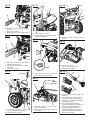
ATTACHING THE WHEEL ASSEMBLY AND
SUPPORT FEET
See Figures 3 - 4.
NOTE: Never place the pressure washer in any position
other than upright.
Locate 2 support feet, 4 lock nuts, and 4 bolts.
Lift the machine and slide the support feet onto the
machine base.
Secure in place using the bolts and lock nuts.
Repeat with second foot.
Locate 2 axles, 2 hitch pins, 2 washers, and 2 wheels.
Insert the axle through the hole in the center of the wheel.
Slide the washer onto the axle.
Lift the machine and slide the axle into the wheel mount-
ing hole in the machine base as shown.
Push the hitch pin into the hole on the end of the axle to
secure the wheel assembly.
NOTE: The hitch pin should be pushed into the axle until
the center of the pin rests on top of the axle.
Repeat with the second wheel.
UNPACKING
This product requires assembly.
Carefully remove the product and any accessories from
the box. Make sure that all items listed in the packing list
are included.
WARNING:
Do not use this product if any parts on the Packing List
are already assembled to your product when you unpack
it. Parts on this list are not assembled to the product by
the manufacturer and require customer installation. Use
of a product that may have been improperly assembled
could result in serious personal injury.
NOTE: This pressure washer is heavy. To avoid back in-
jury, lift with your legs, not your back, and get help when
needed.
Inspect the pressure washer carefully to make sure no
breakage or damage occurred during shipping.
Do not discard the packing material until you have care-
fully inspected and satisfactorily operated the pressure
washer.
If any parts are damaged or missing, please call
1-877-202-1480 for assistance.
PACKING LIST
Pressure Washer
4-Cycle Engine Lubricant
50 ft. High Pressure Hose
Auxiliary Handle
Axle (2)
Bolt (1/4-20 x 1.9 in., Hex Hd.) (4)
High Pressure Hose Storage
Hitch Pin (2)
Injection Hose with Filter
Lock Nut (1/4-20) (8)
Lock Nut (M10) (4)
Quick-Connect Nozzle (4)
Rear Panel
Rubber Grommet
Screw (1.4 in., Phillips Hd.) (4)
Soap Blaster™ Nozzle
Spray Wand
Spray Wand Holder
Spray Wand Storage Hook
Support Foot (2)
Trigger Handle
Trigger Handle Holder
Trigger Handle Storage Hook
Washer (5/8 in.) (2)
Wheel (2)
Operator’s Manual

Page 9 — English
ASSEMBLY
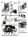
RAISING AND LOWERING THE HANDLE
See Figure 5.
To raise the handle: pull the handle up until the handle
release knob snaps through the locking hole to secure
the handle in place.
To lower the handle: pull the handle release knob out then
lower the handle to the position.
ATTACHING THE REAR PANEL
See Figure 6.
Locate the rear panel, 4 lock nuts, and 4 screws (1.4 in.).
Using a screwdriver (not provided), secure panel to handle
using the screws and nuts.
ATTACHING THE TRIGGER HANDLE HOLDER
AND STORAGE HOOK
See Figure 7.
Raise handle as described in the Raising and Lowering
Handle section.
Locate the trigger handle holder and lock nut.
Insert the trigger handle holder into the handle.
Install lock nut; tighten securely.
Locate the trigger handle storage hook and lock nut.
Insert the trigger handle storage hook into the pressure
washer frame, as shown.
Install lock nut; tighten securely.
ATTACHING THE SPRAY WAND STORAGE HOOK
See Figure 8.
Locate the spray wand storage hook, rubber grommet,
and lock nut.
Slide the spray wand storage hook through the hole in
the rubber grommet.
Insert the spray wand storage hook into the pressure
washer frame, as shown.
Install lock nut; tighten securely.
ASSEMBLING THE TRIGGER HANDLE
See Figure 9.
Place the threaded end of the spray wand in the connector
on the end of the trigger handle.
Turn the connector clockwise until it stops. This secures
the spray wand in place.
When not in use, remove the spray wand from the trigger
handle by turning the connector counterclockwise. Store
the unassembled spray wand in the spray wand storage
area.
ATTACHING THE AUXILIARY HANDLE
See Figure 9.
Place the threaded stud on the end of the auxiliary handle
into the hole in the trigger handle as shown. Turn clock-
wise to tighten.
NOTE: You can install the handle on either the left or right
side of the spray wand, depending on operator prefer-
ence. The handle must always be used to prevent loss
of control and possible serious injury.
To switch sides, remove the auxiliary handle and place
on the opposite side. Tighten securely before use.
CONNECTING HIGH PRESSURE HOSE TO
TRIGGER HANDLE
See Figure 10.
Pull back and hold the collar on the high pressure hose.
Insert the inlet coupler on the trigger handle into the collar.
Release the collar and push until it locks into place. Pull
on the hose to be certain it is properly secured.
ATTACHING INJECTION HOSE
See Figure 11.
Before detergent can be used with this machine, the injection
hose must be attached.
Push the open end of the clear injection hose securely
over the fitting on the pressure washer.
NOTE: Keep injection hose away from hot surfaces.
Place the filtered end of the injection hose in the bottle
of detergent (not provided).

Page 10 — English
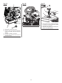
ASSEMBLY
CONNECTING THE GARDEN HOSE TO THE
PRESSURE WASHER
See Figure 12.
CAUTION:
Always observe all local regulations when connnecting
hoses to the water main. Some areas have restrictions
against connecting directly to public drinking water sup-
ply to prevent the feedback of chemicals into the drinking
water supply. Direct connection through a receiver tank
or backflow preventer is usually permitted.
The water supply must come from a water main. NEVER use
hot water or water from pools, lakes, etc. Before connecting
the garden hose to the pressure washer:
Run water through the hose for 30 seconds to clean any
debris from the hose.
Inspect the screen in the water intake.
If the screen is damaged, do not use the machine until
the screen has been replaced.
If the screen is dirty, clean it before connecting the garden
hose to the machine.
To connect the garden hose to the machine:
Uncoil the garden hose.
NOTE: There must be a minimum of 10 feet of unrestricted
hose between the pressure washer intake and the hose
faucet or shut off valve (such as a “Y” shut off connector).
With the hose faucet turned completely off, attach the end of
the garden hose to the pump’s water intake. Tighten by hand.
CONNECTING THE HIGH PRESSURE HOSE TO
THE PUMP
See Figure 13.
After the high pressure hose has been uncoiled and attached
to the spray wand:
Pull back and hold the collar on the pump outlet. Insert
the inlet coupler on the high pressure hose into the collar.
Release the collar and push until it locks into place. Pull
on the hose to be certain it is properly secured.
Pull on the hose to be certain it is properly secured.
CAUTION:
Do not run the pressure washer pump without water sup-
ply connected and turned on, as this may damage the
high pressure seals and decrease pump life. Completely
unwind the hose from its reel or coil and make sure the
hose is not being restricted by tires, rocks, or any other
objects that may lessen or prevent water flow to the
pressure washer.

Page 11 — English
OPERATION
WARNING:
Do not allow familiarity with this product to make you
careless. Remember that a careless fraction of a second is
sufficient to inflict serious injury.
WARNING:
Always wear eye protection with side shields marked to
comply with ANSI Z87.1. Failure to do so could result in
objects being thrown into your eyes resulting in possible
serious injury.
WARNING:
Do not use any attachments or accessories not recom-
mended by the manufacturer of this product. The use of
attachments or accessories not recommended can result
in serious personal injury.
WARNING:
Never direct a water stream toward people or pets, or
any electrical device. Failure to heed this warning could
result in serious injury.
APPLICATIONS
You may use this product for the purposes listed below:
Removing dirt and mold from decks, cement patios, and
house siding
Cleaning boats, motorcycles, outdoor furniture, and grills
CHECKING/ADDING LUBRICANT
See Figure 14.
NOTE: This machine has been shipped with approximately
2 oz. of lubricant in the engine from testing. You must add
lubricant to the engine before starting it the first time.
CAUTION:
Any attempt to start the engine without adding lubricant
will result in engine failure.
Place pressure washer on a flat, level surface.
Unscrew the oil cap / dipstick by turning counter-
clockwise.
Wipe dipstick clean and re-seat in hole; do not re-thread.
Remove dipstick again and check lubricant level. Lu-
bricant level should fall within the upper portion of the
dipstick.
If level is low, add 4-stroke engine lubricant (SAE 30 or
SAE 10W30), until the fluid level rises to the upper portion
of the dipstick (32 oz., 4-cycle engine lubricant provided).
Do not overfill.
Replace the oil cap / dipstick and securely tighten.
NOTE: This engine has a total lubricant capacity of 37.2 oz.
OXYGENATED FUELS
DO NOT USE E85 FUEL. IT WILL VOID YOUR WARRANTY.
NOTE: Fuel system damage or performance problems re-
sulting from the use of an oxygenated fuel containing more
than the percentages of oxygenates stated below are not
covered under warranty.
Ethanol. Gasoline containing up to 10% ethanol by volume
(commonly referred to as E10) is acceptable. E85 is not.

Page 12 — English
OPERATION
ADDING GASOLINE TO THE FUEL TANK
See Figure 15.
WARNING:
Gasoline and its vapors are highly flammable and ex-
plosive. To prevent serious personal injury and property
damage, handle gasoline with care. Keep away from igni-
tion sources, handle outdoors only, do not smoke while
adding fuel, and wipe up spills immediately.
When adding gas to the pressure washer, make sure the
pressure washer is sitting on a flat, level surface. If the engine
is hot, let the pressure washer cool before adding gas. AL-
WAYS fill the fuel tank outdoors with the machine turned off.
NOTE: Use unleaded gas only. DO NOT mix lubricant with gas.
Before removing the fuel cap, clean the area around it.
Remove the fuel cap.
Insert a clean funnel into the fuel tank. Then slowly pour
gasoline into the tank. Fill tank to approximately 1-1/2
in. below the top of the tank neck (this allows for fuel
expansion).
Replace fuel cap and tighten until the cap “clicks”.
Clean up any spills before starting the engine.
WARNING:
Always shut off engine before fueling. Never add fuel to
a machine with a running or hot engine. Move at least
30 ft. from refueling site before starting engine. Do not
smoke and stay away from open flames and sparks!
Failure to follow these instructions could result in serious
personal injury.
STARTING AND STOPPING THE PRESSURE
WASHER
See Figures 16 - 18.
CAUTION:
Do not run the pressure washer pump without water sup-
ply connected and turned on, as this may damage the
high pressure seals and decrease pump life. Completely
unwind the hose from its reel or coil and make sure the
hose is not being restricted by tires, rocks, or any other
objects that may lessen or prevent water flow to the
pressure washer.
Before starting the engine:
Connect all hoses.
Check all fluids (lubricant and gas).
Turn on the garden hose then squeeze the trigger to
relieve air pressure; hold the trigger until a steady stream
of water appears.
To start the engine:
Put the on/off switch in the ON position.
Move the choke to the START position.
Turn the fuel valve to the ON position.
Grasp the recoil starter and pull slowly until resistance is
felt. Give the recoil starter a short, brisk pull to start the
engine.
NOTE: Do not allow the recoil starter to snap back after
starting; return it gently to its original place.
CAUTION:
If the engine does not start after each pull of the recoil
starter, squeeze the trigger to relieve water pressure
before attempting to start the engine again.
Let engine run for several seconds, then move the choke
to the RUN position.
To stop the engine:
Put the on/off switch in the OFF position.
Turn the fuel valve to the OFF position.
Shut off the water supply and pull trigger to release
water pressure.
WARNING:
Hold the handles and wand securely with both hands.
Expect the trigger handle to kickback when the trigger
is pulled due to reaction forces. Failure to do so could
cause loss of control and injury to yourself and others.
USING THE SPRAY WAND TRIGGER
See Figure 19.
For greater control and safety, keep both hands on the
trigger handle at all times.
Pull back and hold the trigger to operate the pressure
washer.
Release the trigger to stop the flow of water through the
nozzle.
To engage the lock out:
Push up on the lock out until it clicks into the slot.
To disengage the lock out:
Push the lock out down and into its original position.
For the most effective cleaning, the spray nozzle should be
between 8 in. and 24 in. from the surface to be cleaned. If
the spray is too close it can damage the cleaning surface.

Page 13 — English
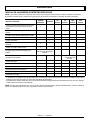
USING THE NOZZLES
See Figure 20.
Each of the nozzles has a different spray pattern. Before
starting any cleaning job, determine the best nozzle for the
job. The following chart offers some general guidelines to
help you choose the best nozzle for your application.
Nozzle Application
0º Red Spot cleaning of high, hard-to-reach areas
• Removing caked-on mud from heavy con-
struction, farm, or lawn equipment
• Cleaning tar, glue, or stubborn stains from
concrete
• Cleaning overhead areas
• Removing rust from steel and oxidation
from aluminum
15º Yellow For narrow surfaces
• Removing heavy mildew stains
• Removing marine growth from boats and
marine equipment
• Removing rust from steel and oxidation
from aluminum
• Removing grease or dirt from equipment
• Removing paint from wood, masonry or
metal
25º Green For general purpose or large surfaces
• General cleaning of dirt, mud, and grime
• Cleaning roofs, gutters, and downspouts
• Removing light mildew stains
• Removing algae and bacteria build-up from
pools
• Rinsing surfaces in preparation for painting
40º White For wide-angle rinsing
• Light cleaning and washing
• Washing and rinsing of painted surfaces
and boats
• Cleaning roofs, windows, patios, and
driveways
Soap
Blaster™
For all detergent applications and for gentle
rinse
WARNING:
NEVER change nozzles without turning off the pressure
washer and locking the lock out on the trigger handle
and never point the wand at your face or at others. The
quick-connect feature contains small springs that could
eject the nozzle with some force. Failure to heed this
warning could cause personal injury.
OPERATION
Using the quick-connect collar, changing nozzles is easy.
To connect a nozzle to the spray wand:
Turn off the pressure washer and shut off the water
supply. Pull trigger to release water pressure.
Engage the lock out on the trigger handle by pushing up
on the lock out until it clicks into the slot.
Push the nozzle into the quick-connect collar until it clicks
in place and is secured properly.
To disconnect a nozzle from the spray wand once the
cleaning job is complete:
Turn off the pressure washer and shut off the water
supply. Pull trigger to release water pressure.
Engage the lock out on the trigger handle by pushing up
on the lock out until it clicks into the slot.
Remove the nozzle by placing hand over nozzle then
pulling back the quick-connect collar.
USING THE HIGH PRESSURE HOSE
The high pressure hose features an outer covering that pro-
vides strength to the hose. If the outer covering becomes
damaged, the hose must be replaced immediately. Do not
use a high pressure hose if the outer covering is damaged.
To prevent damage to the outer covering:
Inspect the hose before every use.
Fully unwrap and straighten hose before use.
Do not allow the high pressure hose to be kinked.
Keep hose away from hot surfaces and sharp edges.
Do not pull pressure washer by high pressure hose.
Do not allow hose to be crushed or wrapped around
objects.
USING THE PRESSURE REGULATOR KNOB
See Figure 21.
Use the pressure regulator knob to adjust the amount of
pressure being delivered through the high pressure hose.
To increase pressure, rotate knob clockwise.
To decrease pressure, rotate knob counterclockwise.
WASHING WITH DETERGENT
See Figures 22 - 23.
As sold, this pressure washer is designed for use with “down-
stream” pressure washer detergents. To convert for use with
“upstream” detergents, contact an authorized customer
service center for more information.
Use only detergents designed for pressure washers; house-
hold detergents, acids, alkalines, bleaches, solvents,
flammable material, or industrial grade solutions can
damage the pump. Many detergents may require mixing
prior to use. Prepare cleaning solution as instructed on the
solution bottle.

Page 14 — English
OPERATION
Remove the cap from the detergent container. Place the
injection hose with filter in the bottle; the filter end should
rest at the bottom of the bottle.
NOTE: The machine setting of this pressure washer is
1:20, which usually allows the use of 1 gallon detergent
without further dilution. Check your detergent instructions
to be sure additional dilution is not necessary.
Install the Soap Blaster™ nozzle on the spray wand.
Spray the detergent on a dry surface using long, even,
overlapping strokes. To prevent streaking, do not allow
detergent to dry on the surface.
For long range detergent application:
With the Soap Blaster™ nozzle installed on the spray wand
and the engine turned off, pull the nozzle up until it clicks
into place.
For short range detergent application:
With the Soap Blaster™ nozzle installed on the spray wand
and the engine turned off, push the Soap Blaster™ nozzle
down as far as it will go.
Before shutting off the engine:
Place the injection hose in a bucket of clean water.
Flush for 1 - 2 minutes (spray clear water through the
spray wand).
Shut off the engine.
NOTE: Shutting off the engine WILL NOT relieve pressure
in the system. Pull trigger to release water pressure.
RINSING WITH THE PRESSURE WASHER
Turn off the pressure washer and shut off the water
supply. Pull trigger to release water pressure.
Engage the lock out on the trigger handle by pushing up
on the lock out until it clicks into the slot.
Remove the nozzle by placing hand over nozzle then
pulling back the quick-connect collar.
Select the right nozzle for the job. Refer to the chart in
Using the Nozzles to determine which nozzle is correct
for your application.
Start at the top of the area to be rinsed and work down,
overlapping the strokes.
MOVING THE PRESSURE WASHER
See Figure 24.
NOTE: Never lift or carry this product using the handle and
never place the pressure washer in any position other than
upright on its wheels.
Turn the pressure washer off and ensure the fuel valve is
closed.
Pull the handle up until the handle release knob snaps into
the locking position (if not already up and locked). Ensure
the lock is secured in the frame hole before moving.
Tilt the machine toward you until it balances on the wheels
then roll the machine to the desired position.
NOTE: Ensure the handle is properly locked in the raised
position before attempting to move the machine.
STORING PRESSURE WASHER AFTER USE
You must pull the trigger to release water pressure before
attempting to disconnect the nozzle or high pressure hose
for storage. Shutting off engine will not relieve pressure in
the system.
For long term storage, see Long-Term Storage Of The
Pressure Washer in the Maintenance section of this manual.
La page est en cours de chargement...
La page est en cours de chargement...
La page est en cours de chargement...
La page est en cours de chargement...
La page est en cours de chargement...
La page est en cours de chargement...
La page est en cours de chargement...
La page est en cours de chargement...
La page est en cours de chargement...
La page est en cours de chargement...
La page est en cours de chargement...
La page est en cours de chargement...
La page est en cours de chargement...
La page est en cours de chargement...
La page est en cours de chargement...
La page est en cours de chargement...
La page est en cours de chargement...
La page est en cours de chargement...
La page est en cours de chargement...
La page est en cours de chargement...
La page est en cours de chargement...
La page est en cours de chargement...
La page est en cours de chargement...
La page est en cours de chargement...
La page est en cours de chargement...
La page est en cours de chargement...
La page est en cours de chargement...
La page est en cours de chargement...
La page est en cours de chargement...
La page est en cours de chargement...
La page est en cours de chargement...
La page est en cours de chargement...
La page est en cours de chargement...
La page est en cours de chargement...
La page est en cours de chargement...
La page est en cours de chargement...
La page est en cours de chargement...
La page est en cours de chargement...
La page est en cours de chargement...
La page est en cours de chargement...
La page est en cours de chargement...
La page est en cours de chargement...
La page est en cours de chargement...
La page est en cours de chargement...
La page est en cours de chargement...
La page est en cours de chargement...
-
 1
1
-
 2
2
-
 3
3
-
 4
4
-
 5
5
-
 6
6
-
 7
7
-
 8
8
-
 9
9
-
 10
10
-
 11
11
-
 12
12
-
 13
13
-
 14
14
-
 15
15
-
 16
16
-
 17
17
-
 18
18
-
 19
19
-
 20
20
-
 21
21
-
 22
22
-
 23
23
-
 24
24
-
 25
25
-
 26
26
-
 27
27
-
 28
28
-
 29
29
-
 30
30
-
 31
31
-
 32
32
-
 33
33
-
 34
34
-
 35
35
-
 36
36
-
 37
37
-
 38
38
-
 39
39
-
 40
40
-
 41
41
-
 42
42
-
 43
43
-
 44
44
-
 45
45
-
 46
46
-
 47
47
-
 48
48
-
 49
49
-
 50
50
-
 51
51
-
 52
52
-
 53
53
-
 54
54
-
 55
55
-
 56
56
-
 57
57
-
 58
58
-
 59
59
-
 60
60
-
 61
61
-
 62
62
-
 63
63
-
 64
64
-
 65
65
-
 66
66


Cat Pumps CT80020 Mode d'emploi
- Catégorie
- Nettoyeurs haute pression
- Taper
- Mode d'emploi
dans d''autres langues
- English: Cat Pumps CT80020 User guide
- español: Cat Pumps CT80020 Guía del usuario