
User Guide
使用说明
使用說明
ユーザーガイド
사용자 가이드
Handbuch
Guía de usuario
Guide d’utilisateur
Guida per l’Utente
Gebruikershandleiding
Manual do utilizador
Руководство пользователя
2023.08v1.0
DJI Video Receiver

2
Contents
CHS
CHT
EN
JP
KR
Disclaimer and Warning 5
Introduction 5
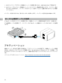
Installation and Connection 7
Activation 8
Linking 9
Display Screen Operations 11
Appendix 13
免责声明和警告 15
简介 15
安装连线 17
激活 18
对频 19
屏幕操作 21
附录 23
免責聲明和警告 25
簡介 25
安裝連線 27
啟動 28
配對 29
螢幕操作 31
附錄 33
35
35
37
38
39
41
43
고지 사항 및 경고 45
소개 45
설치 및 연결 47
활성화 48
연동 49
디스플레이 화면 조작 51
부록 53

3
DE
ES
FR
IT
NL
Haftungsausschluss und Warnhinweise 55
Einführung 55
Montage und Anschluss 58
Aktivierung 59
Kopplung 60
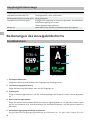
Bedienungen des Anzeigebildschirms 62
Anhang 64
Renuncia de responsabilidad y advertencia 66
Introducción 66
Instalación y conexión 69
Activación 70
Vinculación 71
Operaciones en la pantalla de visualización 74
Apéndice 76
Clause exclusive de responsabilité et mise en garde 78
Introduction 78
Installation et connexion 80
Activation 81
Appairage 82
Opérations sur l’écran d’affichage 85
Annexe 87
Limitazioni di responsabilità e avvertenze 89
Introduzione 89
Installazione e collegamento 91
Attivazione 92
Collegamento 93
Operazioni dello schermo di visualizzazione 96
Appendice 98
Disclaimer en waarschuwing 100
Inleiding 100
Installatie en aansluiting 102
Activering 103
Koppelen 104
Schermbewerkingen weergeven 107
Bijlage 109

4
Exoneração de Responsabilidade e Aviso 111
Introdução 111
Instalação e ligação 113
Ativação 114
Ligação 115
Operações do ecrã de visualização 118
Apêndice 120
Отказ от ответственности и предупреждение 122
Введение 122
Установка и подключение 124
Активация 125
Сопряжение 126
Управление дисплеем 129
Приложение 131
RU
PT

5
EN
Disclaimer and Warning
Carefully read this entire document and all safe and lawful practices provided before use.
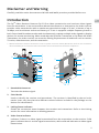
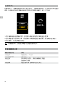
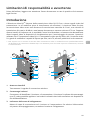
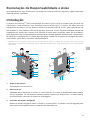
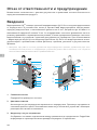
Introduction
The DJITM Video Receiver features DJI O3 Pro video transmission and receives video signals
from the transmitter. In an environment without interference or obstruction, the video receiver
provides video transmission with a maximum transmission range of 6 km*, a bitrate of up to
40 Mbps, and a minimum end-to-end latency of 70 ms. It supports multiple frequency bands in
both Control and Broadcast modes and simultaneously outputs multiple video signals to display
devices for remote monitoring. When used with the DJI Video Transmitter or DJI Ronin 4D Video
Transmitter, the video receiver can meet the lming requirements of mediums such as movies,
TV series, advertisements, and documentaries.
* Measured with the video transmission control system in Control mode (Broadcast mode in the transmitter
device disabled) in an unobstructed environment free of interference with FCC compliance.
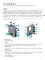
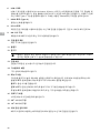
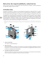
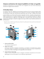
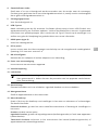
1. Detachable Antennas
Transmit the wireless signal.
2. Color Marks
Used to identify the receiver and transmitter. The receiver is identified by the red color
marks. Users can also place the dierent colored stickers included in the package on the
devices for identication.
3. Linking Status Indicator
Shows the connection status between the receiver and transmitter. Refer to the Linking
section for more information on blinking patterns.
4. Video Status Indicator
Indicates if there is a video signal transmitted from the transmitter to the receiver. Solid
green indicates there is a video signal transmission, while solid red indicates no video signal
transmission.
1
2
3
4
5
6
7
8
9
9
10
11
12
13
14
15
16
1718
19

6
EN
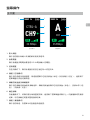
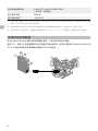
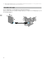
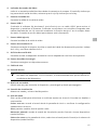
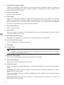
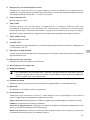
5. SDI Output Ports
Output the video signal.
6. USB-C Port
Connect to the DJI Assistant 2 (Ronin Series) software using a USB-C cable for device
activation and rmware updates. Connect headphones with a built-in mic for voice calls. It
is required to set the Type-C function on the receiver before use. Refer to the Menu section
for more information.
7. HDMI Port (Type A)
Outputs the video signal.
8. DC-in Port
Supplies power to the video receiver using the provided power cable. Voltage 6-18 V and
max current 2 A.
9. M4 Screw Holes
Mount the battery adapter or other adapters for expansion.
10. Power Output Port
Supplies power to an external device.
11. Air Vent
12. Air Intake
• DO NOT cover the air vent, air intake, or both sides of the battery adapter if mounted.
Otherwise, the performance of the device may be aected due to overheating.
13. Power Button
Press once to power on. Press and hold to power o.
14. Display Screen
Displays the device status and menu.
15. Menu Dial
Turn or press the dial to select or conrm settings in the menu. See details below.
Press once: enter the menu from the home screen, or conrm settings in the menu.
Turn: switch between options.
Press and hold: enter linking status (Control mode) or search for devices (Broadcast mode).
Press twice: in the home screen, select the channel (Control mode) or device number
(Broadcast mode).
16. Back Button
Press to return to the previous screen of the menu.
17. 3/8″-16ScrewHole
18. 1/4″-20ScrewHoles
19. External Power Input Port
Mount the battery adapter and compatible battery to supply power to the video receiver.

7
EN
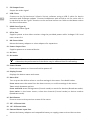
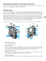
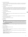
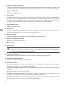
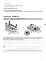
Installation and Connection
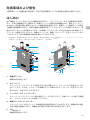
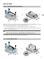
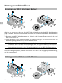
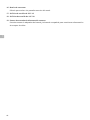
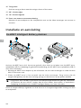
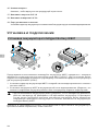
Mounting the WB37 Intelligent Battery
Before rst use, activate the WB37 battery by charging with the WB37 Battery Charging Hub
(USB-C). Refer to the WB37 Battery Charging Hub (USB-C) User Guide for more information.
1. Mount the WB37 battery adapter to the back of the video receiver and tighten the three
M4×12 screws.
2. Insert the WB37 battery into the battery compartment of the video receiver. Make sure that
the battery release button pops up and the battery clicks into place.
• Make sure to use the WB37 battery within the operating temperature range. DO NOT
disassemble or pierce the battery in any way. Otherwise, the battery may leak, catch re,
or explode. Refer to the WB37 Intelligent Battery Safety Guidelines for more information.
Press and hold the release button and push the battery in the opposite direction to remove it.
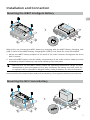
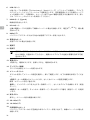
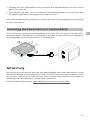
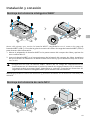
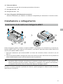
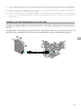
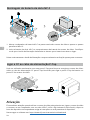
Mounting the NP-F Series Battery

8
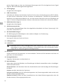
EN
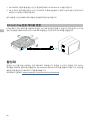
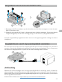
1. Mount the NP-F battery adapter to the back of the video receiver and tighten the four M4×12
screws.
2. Insert the NP-F series battery into the battery compartment of the video receiver. Make sure
that the battery release button pops up and the battery clicks into place.
Press and hold the release button and push the battery in the opposite direction to remove it.
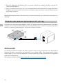
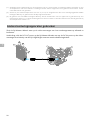
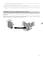
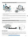
Connecting the DC to P-Tap Power Cable
A battery with a P-Tap port can be used to provide power to the video receiver. Use the
provided DC to P-Tap power cable to connect the P-Tap port of the battery and the DC-in port of
the video receiver.
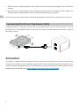
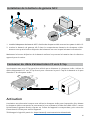
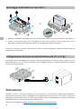
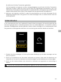
Activation
Activation is required when using the video receiver for the first time. Power on the video
receiver and connect it to a computer using a USB-C cable. Launch DJI Assistant 2 (Ronin Series),
click the corresponding device icon, and follow the on-screen instructions to activate the device.
Download the software from: https://www.dji.com/transmission/downloads

9
EN
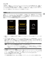
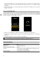
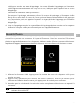
Linking
The video receiver must be linked to the transmitter device before use. The video transmission
system of the video receiver oers Control mode and Broadcast mode for connection between
the video receiver and transmitter device, which use different linking methods. Refer to the
following section for instructions and linking status indicator descriptions.
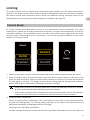
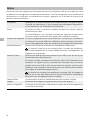
Control Mode
In Control mode (with Broadcast mode in the transmitter device disabled), the video
transmission system has a longer transmission distance, stronger anti-interference, and more
selectable channels. The transmitter device can also receive the control signal from the video
receiver when connecting a DJI Pro accessory, such as the DJI Master Wheels to the video
receiver for remote control.
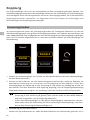
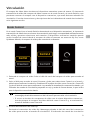
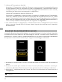
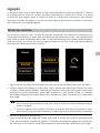
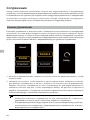
1. Power on the video receiver. Press the menu dial on the video receiver to enter the menu.
2. Press the dial to enter the Connect menu, turn the dial to select Control in the menu, and
press the dial to conrm. Select to set the video receiver to Control A or Control B and press
the dial again to conrm. The display screen shows Linking and the linking status indicator
blinks red and green alternately, indicating the device is linking.
• If the video receiver is in Control mode and is set to the desired Control A or Control
B, press and hold the menu dial directly to enter linking.
• If two video receivers will be connected to the same transmitter device, link with the
Control A video receiver rst and then link with the Control B video receiver.
3. Using DJI Video Transmitter:
Power on the DJI Video Transmitter. Press and hold the menu dial on the video transmitter
to enter the linking status. The linking status indicator on the video transmitter blinks red
and green alternately, indicating the device is linking.
Using DJI Ronin 4D Video Transmitter:
To start linking, hold the link button on the Ronin 4D Video Transmitter or go to the menu on
Connect
Control
Broadcast
Control A
Control B
Linking...

10
EN
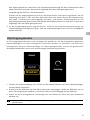
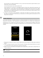
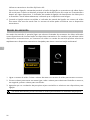
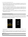
1. Power on the video receiver. Press the menu dial on the video receiver to enter the menu.
2. Press the dial to enter the Connect menu, turn the dial to select Broadcast in the menu, and
then press the dial to conrm.
3. Wait for the search results to be complete and select a device to connect.
• In Broadcast mode, press and hold the dial to refresh the search results.
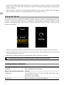
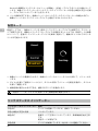
Linking Status Indicator
Linking Status Indicator Description
Solid red Device started, not connected.
Blinks red and green alternately Linking.
Solid green Successfully linked in Control mode. Wireless video
transmission is normal.
Broadcast mode enabled.
Blinks red Device malfunction. Contact DJI Support.
Connect
Control
Broadcast
Searching...
the Ronin 4D High-Bright Main Monitor, tap Transmission, and then Link Device. The linking
status indicator on the video transmitter blinks red and green alternately, indicating the
device is linking.
4. When linking is complete, the linking status indicator on the video receiver turns solid green
and the video receiver can communicate with the transmitter device.
Broadcast Mode
In Broadcast mode, an unlimited number of video receivers used as monitoring devices can
connect to the transmitter device. In scenarios using multiple transmitter devices, video
receivers in Broadcast mode can select the desired transmitter device quickly to achieve multi-
channel monitoring.

11
EN
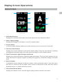
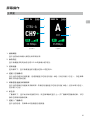
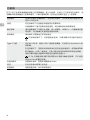
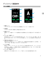
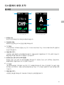
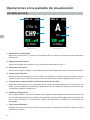
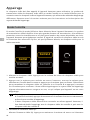
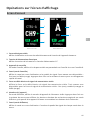
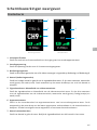
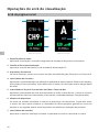
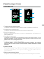
Display Screen Operations
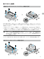
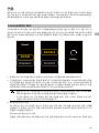
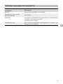
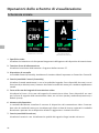
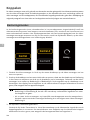
Home Screen
1. VideoSpecications
Displays the resolution and frame rate of the input from the transmitter device.
2. Power Supply Voltage
Displays the voltage of the battery or the DC-in power input.
3. Control Device
In Control mode, displays whether the video receiver is set to Control A or Control B.
4. Channel (Control Mode)
Displays the current channel in use and its signal quality. There are two statuses, including
strong (green) and weak (red). Press the menu dial twice for quick channel switch.
5. Video Transmission Signal Strength and Bitrate
Displays the video transmission signal strength and bitrate. There are three statuses for the
video transmission signal strength, including strong (green), moderate (orange), and weak
(red).
6. Device Number
In Broadcast mode, displays the device number of the transmitter device. Press the menu
dial twice to view the last recorded search results in Broadcast mode, and then switch
between devices or refresh the search results.
7. Channel (Broadcast Mode)
Displays the channel in use. View the signal quality of each channel in the menu.
CH1
A
35.9Mbps
RX
CTRL-A
CH9
35.9Mbps
RX
1080P 24 16.8V 1080P 24 16.8V
Control Mode Broadcast Mode
1 2
3
4
5
6
7

12
EN
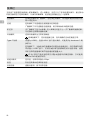
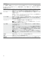
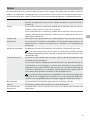
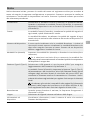
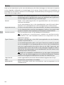
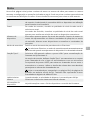
Menu
On the home screen, press the menu dial on the video receiver to enter the menu and perform
the following conguration and operations. Turn or press the dial to select or conrm settings
in the menu. Press the back button to return to the previous screen.
Connect Select Control mode or Broadcast mode. When Control mode is
selected, it is required to set the device in use to Control A or Control B.
Channel In Control mode, view the signal quality of each channel and select the
channel.
In Broadcast mode, view the signal quality of each channel only to
assist channel selection in the transmitter device.
Device Number This menu will appear only in Broadcast mode. The last search results
in Broadcast mode will be displayed after entering the menu. Switch
between devices or refresh the search results.
Fan Mode Set the fan mode to Standard or Low Noise.
If Low Noise is selected, the fan mode will switch to Standard
automatically when the temperature of the device is too high.
Type-C Function Select USB when using the USB-C port for the rmware update in DJI
Assistant 2.
In Control mode, set the Type-C function on both the transmitter and
receiver to Voice Call and connect headphones with a built-in mic to the
USB-C ports to enable voice calls between the transmitter and receiver.
Use the volume buttons on the headphones to adjust the volume for
voice calls.
View the compatible headphones on the FAQ page of the product
page on the ocial DJI website. Other 48kHz/16bit digital headphones
are also supported.
Low Latency When enabled, the frame rate is converted to 60fps.
Language Select the system language in the language list.
Device Info View information such as the device SN and rmware version.

13
EN
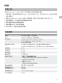
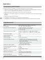
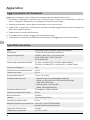
Appendix
Firmware Update
Update the video receiver using the DJI Assistant 2 (Ronin Series) software.
1. Power on the device. Make sure the Type-C function is set to USB on the menu. Connect the
device to a computer with a USB-C cable.
2. Launch DJI Assistant 2 (Ronin Series) and log in with a DJI account.
3. Select the device and click Firmware Update on the left side of the screen.
4. Select the rmware version.
5. The rmware will download and update automatically.
6. The device will restart automatically after the rmware update is complete.
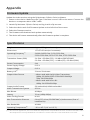
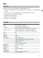
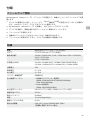
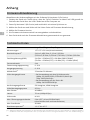
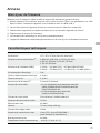
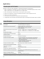
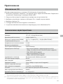
Specications
Weight Approx. 350 g (receiver only, excl. antennas)
Dimensions 127×87×26 mm (excl. antennas)
Operating Frequency[1] 2.4000-2.4835 GHz, 5.150-5.250 GHz,
5.250-5.350 GHz, 5.470-5.725 GHz, 5.725-5.850 GHz
Transmitter Power (EIRP) 2.4 GHz: <33 dBm (FCC), <20 dBm (SRRC/CE/MIC)
5.8 GHz: <33 dBm (FCC), <14 dBm (CE), <23 dBm (SRRC)
Power Consumption 9 W
Power Supply Voltage 6-18 V
Output Voltage 6-18 V
Battery Life[2] 3 hours 50 minutes
Output Video Format • When used with the DJI Video Transmitter:
1080p: 23.98/24/25/29.97/30/50/59.94/60fps
720p: 50/59.94/60fps
• When used with Ronin 4D:
1080p: 24/25/30/50/60fps
Output Audio Format SDI embedded, HDMI embedded
Video Transmission System O3 Pro
Max Bitrate 40 Mbps
Latency 70 ms (1080p 60fps)
Video Coding Format H.264
Max Transmission Distance 6 km (FCC), 4 km (CE/SRRC/MIC) (Unobstructed, free of
interference)
Max Bandwidth 40 MHz
Operating Temperature[3] -10° to 45° C (14° to 113° F)
[1] Due to local regulations, the 5.1/5.2/5.8 GHz frequencies are prohibited in some countries and the 5.1/5.2
GHz frequencies are only allowed for use indoors in some countries. 5.600-5.650 GHz is not used.

14
EN
[2] Tested in a room temperature of 25° C (77° F) when powered by a fully charged WB37 Intelligent Battery
and used with the DJI Video Transmitter.
[3] When using the WB37 Intelligent Battery, it is recommended to operate the device in a temperature above
0° C. Take measures to keep the battery warm when using in a temperature below 0° C.
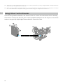
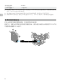
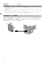
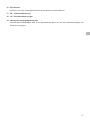
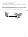
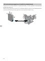
Using Other Control Devices
Connect the DJI Master Wheels to the video receiver to control the transmitter device remotely.
Connection: connect the DC-OUT port on the DJI Master Wheels to the DC-IN port on the video
receiver using the DJI High-Bright Remote Monitor Controller Cable.

15
CHS
免责声明和警告
使用本产品之前,请仔细阅读并遵循本文及与本产品相关的所有安全与合规操作指引。
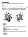
简介
DJITM 图传接收器采用 DJI O3 Pro 图传技术,接收发射端视频信号。在无干扰和无遮挡环境下,
可实现最大可达 6千米 *地面端通信距离与 40 Mbps 码流高清图传,端到端延时低至 70 ms。
支持多种频段,具备控制模式和广播模式,可同时输出多路视频信号到显示设备,实现远程监看。
配合 DJI 图传发射器或 DJI Ronin 4D 图传发射器使用时,可满足影视剧、广告、纪录片等各类
题材的拍摄需求。
*无线图传控制系统切换至控制模式(发射端广播模式关闭),在 FCC 标准无干扰环境下测得。
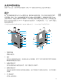
1. 可拆卸天线
传输无线信号。
2. 色标
用于区分接收器和发射器。接收器此处为红色圆圈。用户亦可将包装内附带的不同颜色贴
纸粘贴在设备上进行区分。
3. 对频状态指示灯
指示接收器和发射端的连接状态。指示灯描述见对频章节。
4. 视频状态指示灯
显示发射端是否有视频信号传输至接收器。绿灯常亮表示有视频信号传输,红灯常亮表示
无传输。
5. SDI 输出接口
用于输出视频信号。
1
2
3
4
5
6
7
8
9
9
10
11
12
13
14
15
16
1718
19

16
CHS
6. USB-C 接口
使用 USB-C 线连接至 DJI Assistant 2 (Ronin 系列 )调参软件以激活设备、升级固件。亦可
插入自带麦克风的耳机进行语音通话。使用前需在接收器的 Type-C 功能设置中切换接口用
途。详见菜单栏章节。
7. HDMI 接口(A口)
用于输出视频信号。
8. DC-IN 电源输入接口
可通过标配的供电线实现对图传接收器的供电。供电电压 6-18 V,电流最大 2 A。
9. M4 螺纹接口
用于安装电池转接板以及各类转接件的扩展。
10. 对外供电接口
对外部设备进行供电。
11. 出风口
12. 进风口
• 使用时请勿遮挡出风口及进风口或电池转接板的两侧(若已安装),以免设备温度
过高影响性能。
13. 电源按键
短按开机、长按关机。
14. 显示屏幕
显示设备状态及菜单。
15. 菜单拨轮
可通过转动和按压拨轮进行选择及确认等,以操作屏幕菜单。具体功能如下。
短按:由主界面进入菜单栏;在菜单栏中确认选择。
转动:切换选项。
长按:进入对频状态(控制模式)或搜索设备(广播模式)。
双击:在主界面选择信道(控制模式)或机位号(广播模式)。
16. 返回按键
控制屏幕菜单返回上一级。
17. 3/8″-16 螺纹接口
18. 1/4″-20 螺纹接口
19. 外部电源输入接口
通过连接不同的电池转接板以安装电池,用于为接收器供电。

17
CHS
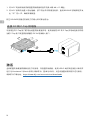
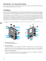
安装连线
安装 WB37 智能电池
首次使用需通过 WB37 充电管家(USB-C)为 WB37 电池充电以激活电池。详情参阅《WB37
充电管家(USB-C)使用说明》。
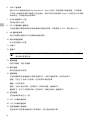
1. 将WB37 电池转接板安装至图传接收器背面并旋紧 3颗M4×12 螺丝。
2. 将WB37 智能电池置入电池插槽,按下电池并将其推至底部,直到 RELEASE 按键弹起并发
出“咔”的一声,确保安装稳固。
• 务必在工作环境温度范围内使用 WB37 电池。禁止以任何方式拆解或用尖利物体刺破电
池。否则将会引起电池着火甚至爆炸。详情参阅《WB37 智能电池安全使用指引》。
按住 RELEASE 按键沿安装反方向用力即可取出电池。
安装 NP-F 系列电池

18
CHS
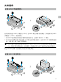
1. 将NP-F 电池转接板安装至图传接收器背面并旋紧 4颗M4×12 螺丝。
2. 将NP-F 系列电池置入电池插槽,按下电池并将其推至底部,直到 RELEASE 按键弹起并发
出“咔”的一声,确保安装稳固。
按住 RELEASE 按键沿安装反方向用力即可取出电池。
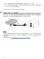
连接 DC 转P-Tap 供电线
可使用含有 P-Tap 接口的电池给图传接收器供电。使用标配的 DC 转P-Tap 供电线连接供电电
池的 P-Tap 接口及图传接收器的 DC-IN 电源输入接口。
激活
全新的图传接收器需要激活后方可使用。开启图传接收器,使用 USB-C 线将其连接至计算机并
运行 DJI Assistant 2 (Ronin 系列 )调参软件,登录 DJI 账号,点击设备图标按照提示进行激活。
调参软件下载地址:https://www.dji.com/transmission/downloads

19
CHS
对频
图传接收器需与发射端设备对频后方可使用。接收器与发射端设备的连接模式分为控制模式和
广播模式,其对频方式略有不同。详见以下操作说明及对频状态指示灯描述。
控制模式
控制模式下(发射端设备广播模式关闭),图传系统的传输距离更远,抗干扰能力更强,可设
置信道更多。同时,发射端设备可接收到图传接收器的控制信号,如接入 DJI 大师摇轮等专业配
件进行远程控制。
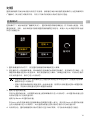
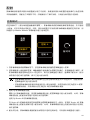
1. 图传接收器开机状态下,按压图传接收器的菜单拨轮进入菜单。
2. 按压拨轮进入连接模式菜单,转动拨轮在连接模式中选择控制模式,按压拨轮进行确认。选
择图传接收器为控制 A或控制 B,再次按压拨轮进行确认。屏幕显示配对中,对频状态指示
灯红绿交替闪烁,表示已进入对频状态。
• 若图传接收器已处于控制模式且已设置为所需的控制 A或控制 B,则直接长按菜单
拨轮即可进入对频状态。
• 若两个图传接收器同时连接至同一发射端设备,则需先对频设置为控制 A的图传接
收器,然后再对频设置为控制 B的图传接收器。
3. 使用 DJI 图传发射器:
开启 DJI 图传发射器,长按图传发射器上的菜单拨轮以进入对频状态,此时图传发射器上的
对频状态指示灯红绿交替闪烁。
使用 DJI Ronin 4D 图传发射器:
在Ronin 4D 的机身高亮监视器菜单中选择图传设置 > 配对,或长按 Ronin 4D 图传发射器
上的对频按键以进入对频状态,此时图传发射器上的对频状态指示灯红绿交替闪烁。
4. 对频成功后,图传接收器的对频状态指示灯显示绿灯常亮,可与发射端设备进行通信。
配对中
连接
模式
控制模式
广播模式
控制 A
控制 B

20
CHS
广播模式
广播模式下,图传接收器作为监看设备,其连接数量不设限制。在有多个发射端设备的场景,
以广播模式连接的图传接收器可快速切换发射端机位,实现多路监看。
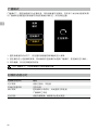
1. 图传接收器开机状态下,按压图传接收器的菜单拨轮进入菜单。
2. 按压拨轮进入连接模式菜单,转动拨轮在连接模式中选择广播模式,按压拨轮进行确认。
3. 等待搜索,然后选择连接的设备。
• 在广播模式下,长按菜单拨轮可刷新搜索结果。
对频状态指示灯
对频状态指示灯 描述
红灯常亮 设备已启动,未连接
红绿灯交替闪烁 正在对频
绿灯常亮 控制模式对频成功,无线图传正常连接
广播模式已开启
红灯闪烁 设备内部故障,请联系 DJI 技术支持
连接
模式
控制模式
广播模式
正在搜索...
La page charge ...
La page charge ...
La page charge ...
La page charge ...
La page charge ...
La page charge ...
La page charge ...
La page charge ...
La page charge ...
La page charge ...
La page charge ...
La page charge ...
La page charge ...
La page charge ...
La page charge ...
La page charge ...
La page charge ...
La page charge ...
La page charge ...
La page charge ...
La page charge ...
La page charge ...
La page charge ...
La page charge ...
La page charge ...
La page charge ...
La page charge ...
La page charge ...
La page charge ...
La page charge ...
La page charge ...
La page charge ...
La page charge ...
La page charge ...
La page charge ...
La page charge ...
La page charge ...
La page charge ...
La page charge ...
La page charge ...
La page charge ...
La page charge ...
La page charge ...
La page charge ...
La page charge ...
La page charge ...
La page charge ...
La page charge ...
La page charge ...
La page charge ...
La page charge ...
La page charge ...
La page charge ...
La page charge ...
La page charge ...
La page charge ...
La page charge ...
La page charge ...
La page charge ...
La page charge ...
La page charge ...
La page charge ...
La page charge ...
La page charge ...
La page charge ...
La page charge ...
La page charge ...
La page charge ...
La page charge ...
La page charge ...
La page charge ...
La page charge ...
La page charge ...
La page charge ...
La page charge ...
La page charge ...
La page charge ...
La page charge ...
La page charge ...
La page charge ...
La page charge ...
La page charge ...
La page charge ...
La page charge ...
La page charge ...
La page charge ...
La page charge ...
La page charge ...
La page charge ...
La page charge ...
La page charge ...
La page charge ...
La page charge ...
La page charge ...
La page charge ...
La page charge ...
La page charge ...
La page charge ...
La page charge ...
La page charge ...
La page charge ...
La page charge ...
La page charge ...
La page charge ...
La page charge ...
La page charge ...
La page charge ...
La page charge ...
La page charge ...
La page charge ...
La page charge ...
La page charge ...
La page charge ...
-
 1
1
-
 2
2
-
 3
3
-
 4
4
-
 5
5
-
 6
6
-
 7
7
-
 8
8
-
 9
9
-
 10
10
-
 11
11
-
 12
12
-
 13
13
-
 14
14
-
 15
15
-
 16
16
-
 17
17
-
 18
18
-
 19
19
-
 20
20
-
 21
21
-
 22
22
-
 23
23
-
 24
24
-
 25
25
-
 26
26
-
 27
27
-
 28
28
-
 29
29
-
 30
30
-
 31
31
-
 32
32
-
 33
33
-
 34
34
-
 35
35
-
 36
36
-
 37
37
-
 38
38
-
 39
39
-
 40
40
-
 41
41
-
 42
42
-
 43
43
-
 44
44
-
 45
45
-
 46
46
-
 47
47
-
 48
48
-
 49
49
-
 50
50
-
 51
51
-
 52
52
-
 53
53
-
 54
54
-
 55
55
-
 56
56
-
 57
57
-
 58
58
-
 59
59
-
 60
60
-
 61
61
-
 62
62
-
 63
63
-
 64
64
-
 65
65
-
 66
66
-
 67
67
-
 68
68
-
 69
69
-
 70
70
-
 71
71
-
 72
72
-
 73
73
-
 74
74
-
 75
75
-
 76
76
-
 77
77
-
 78
78
-
 79
79
-
 80
80
-
 81
81
-
 82
82
-
 83
83
-
 84
84
-
 85
85
-
 86
86
-
 87
87
-
 88
88
-
 89
89
-
 90
90
-
 91
91
-
 92
92
-
 93
93
-
 94
94
-
 95
95
-
 96
96
-
 97
97
-
 98
98
-
 99
99
-
 100
100
-
 101
101
-
 102
102
-
 103
103
-
 104
104
-
 105
105
-
 106
106
-
 107
107
-
 108
108
-
 109
109
-
 110
110
-
 111
111
-
 112
112
-
 113
113
-
 114
114
-
 115
115
-
 116
116
-
 117
117
-
 118
118
-
 119
119
-
 120
120
-
 121
121
-
 122
122
-
 123
123
-
 124
124
-
 125
125
-
 126
126
-
 127
127
-
 128
128
-
 129
129
-
 130
130
-
 131
131
-
 132
132
-
 133
133


dans d''autres langues
- italiano: dji Transmission Guida utente
- español: dji Transmission Guía del usuario
- Nederlands: dji Transmission Gebruikershandleiding
- português: dji Transmission Guia de usuario
- 日本語: dji Transmission ユーザーガイド
Documents connexes
-
dji 1000012552 Mode d'emploi
-
dji Assistant 2 (Enterprise Series) Mode d'emploi
-
dji Assistant 2 (Enterprise Series) Mode d'emploi
-
dji Assistant 2 (Enterprise Series) Mode d'emploi
-
-
-
-
-
dji Pilot Guide de démarrage rapide
-
dji Assistant 2 (Enterprise Series) Mode d'emploi