Skyblade STOL Series Guide d'installation
- Catégorie
- Ventilateurs ménagers
- Taper
- Guide d'installation

Where Form Follows Function Where Form Follows Function Where Form
Follows Function Where Form Follows Function Where Form Follows
Function Where Form Follows Function Where Form Follows Function
Where Form Follows Function Where Form Follows Function Where Form
Follows Function Where Form Follows Function Where Form Follows
Function Where Form Follows Function Where Form Follows Function
Where Form Follows Function Where Form Follows Function Where Form
Follows Function Where Form Follows Function Where Form Follows
Function Where Form Follows Function Where Form Follows Function
Where Form Follows Function Where Form Follows Function Where Form
Follows Function Where Form Follows Function Where Form Follows
Function Where Form Follows Function Where Form Follows Function
Where Form Follows Function Where Form Follows Function Where Form
Follows Function Where Form Follows Function Where Form Follows
Function Where Form Follows Function Where Form Follows Function
Where Form Follows Function Where Form Follows Function Where Form
Follows Function Where Form Follows Function Where Form Follows
Function Where Form Follows Function Where Form Follows Function
Where Form Follows Function Where Form Follows Function Where Form
Follows Function Where Form Follows Function Where Form Follows
Function Where Form Follows Function Where Form Follows Function
Where Form Follows Function Where Form Follows Function Where Form
Follows Function Where Form Follows Function Where Form Follows
Function Where Form Follows Function Where Form Follows Function
Where Form Follows Function Where Form Follows Function Where Form
Follows Function Where Form Follows Function Where Form Follows
Function Where Form Follows Function Where Form Fo
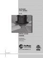
SkyBlade
STOL Series
12’-24’
Installation
Manual
Custom Designed
Reduced Maintenance
STOL Technology
Cat.No.SBF1-1
www.SKYBLADEFANS.com
Patent pending

2
SKYBLADE FANS -
Where Form Follows Function
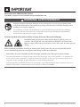
READ AND SAVE THESE INSTRUCTIONS.
A printable, electronic version is available online at skybladefans.com.
Improper installation, adjustment, alteration, service or maintenance can cause property damage, injury
or death. Read and understand the installation, operating and maintenance instructions thoroughly before
installing or servicing this equipment.
Une installation, un réglage, une modication, un service ou d’entretien peuvent causer des dommages
matériels, des blessures ou la mort. Lire et comprendre les instructions d’installation, d’exploitation et
d’entretien avant d’installer ou de réparer ce matériel.
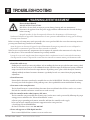
To Reduce the Risk of Fire, Electric Shock, or Injury to Persons, Observe the Following:
Installation work and electrical wiring must be done by qualied person(s) in
accordance with all applicable codes and standards, including re-rated construction.
Failure to comply could result in personal injury, electric shock, death, re and/or property
damage.
Before attempting installation, servicing or cleaning unit, switch power o at the service panel and lock the
service disconnecting means to prevent power from being switched on accidentally.
Pour réduire le risque d’incendie, de choc électrique ou de blessures, observer les points suivants:
Les travaux d’installation et le câblage électrique doivent être eectués par une personne qualiée (s) en conformité avec
tous les codes et normes applicables, y compris la construction coupe-feu. Le non-respect peut entraîner des blessures
corporelles, de choc électrique, la mort, un incendie et / ou des dommages matériels.
Avant d’entreprendre l’installation, l’entretien ou un nettoyage, coupez l’alimentation électrique au panneau de service et
bloquez les dispositifs de sectionnement pour éviter une mise en marche accide
ntelle.
WARNING/ AVERTISSEMENT
!
!
IMPORTANT
!

SKYBLADE FANS -
Where Form Follows Function 3
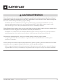
e installation must be in accordance with the requirements specied in this installation manual and with any additional
requirements set forth by the national electric code (NEC), ANSI/NFPA 70-1999, and all local codes. Failure to comply with
these codes could result in personal injury or property damage.
L’installation doit être en conformité avec les exigences spéciées dans le présent manuel d’installation et avec des
exigences supplémentaires prévues par le code électrique national (NEC), ANSI / NFPA 70-1999, et tous les codes
locaux. Le non respect de ces codes peut entraîner des blessures ou des dommages matériels.
e installation of this fan requires the use of power tools. Follow the safety procedures found in the owner’s manual of these
tools and do not use them for purposes other than those intended by the manufacturer.
L’installation de ce ventilateur nécessite l’utilisation d’outils électriques. Suivez les consignes de sécurité gurant dans le
manuel du propriétaire de ces outils et ne pas les utiliser à des ns autres que celles prévues par le fabricant.
is unit has an unguarded impeller. Do not use in locations readily accessible to people or animals.
Cet appareil possède une roue sans surveillance. Ne pas utiliser dans des endroits facilement accessibles pour les
personnes ou les animaux.
Use this unit only in the manner intended by the manufacturer. If you have questions, contact the manufacturer. e limited
warranty does not cover equipment damage or failure that is caused by improper installation.
Utiliser cet appareil uniquement de la manière prévue par le fabricant. Si vous avez des questions, contactez le fabricant.
La garantie limitée ne couvre pas les dommages à l’équipement ou de l’échec qui est causé par une mauvaise installation.
CAUTION /ATTENTION
!
IMPORTANT
!

4
SKYBLADE FANS -
Where Form Follows Function
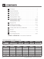
Contents
1 Fan Diagram ................................................................................................................ 6
2 Important Information .............................................................................................. 7
3 Mounting Considerations ......................................................................................... 8
4 Preparing the Work Site ............................................................................................. 9
5 Mounting Method 1: I-Beam .................................................................................. 10
6 Mounting Method 2: Angle Iron ...................................................................... 11-15
Mounting Method 3: Purlins ............................................................................ 16-17
Mounting Method 3: Purlins ............................................................................ 18-19
7 Hanging the Fan ................................................................................................. 20-21
8 Installing Guy Wires/Gripple ............................................................................ 22-23
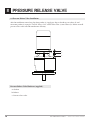
Pressure Relief Valve Installation ............................................................................ 24
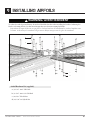
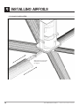
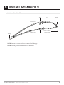
9 Installing Airfoils, Motor Cover, and Motor Hub .......................................... 25-31
10 Electrical .............................................................................................................. 32-38
11 Troubleshooting ........................................................................................................ 39
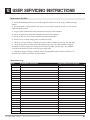
12 User Servicing Instructions ............................................................................... 40-41
SkyBlade
®
and SkyBlade Fans
®
are the trademarks of Skyblade Fans.
STOL Airfoils (patent pending)
STOL Control and Power Assembly (patent pending)
Model Description Length (Y) Width (X) Height (Z) Shipping Weight
STOL Control & Airfoil Assembly 33.0” (839mm) 30.5” (775mm) 30.5” (775mm) 145 lbs. (65 kg.)
Model Description Width (X) Length (Y) Height (Z) Shipping Weight
1236-6 12’ / 3.6M Fan 5’-6” (1680mm) 24.0” (610mm) 17.0” (432mm) 125 lbs. (57 kg.)
1443-6 14’ / 4.3M Fan 6’-6” (1982mm) 24.0” (610mm) 17.0” (432mm) 140 lbs. (64 kg.)
1649-6 16’ / 4.9M Fan 7’-6” (2286mm) 24.0” (610mm) 17.0” (432mm) 155 lbs. (71 kg.)
1855-6 18’ / 5.5M Fan 8’-6” (2591mm) 24.0” (610mm) 17.0” (432mm) 170 lbs. (77 kg.)
2061-6 20’ / 6.1M Fan 9’-6” (2896mm) 24.0” (610mm) 17.0” (432mm) 185 lbs. (84 kg.)
2473-6 24’ / 7.3M Fan 11’-6” (3505mm) 24.0” (610mm) 17.0” (432mm) 215 lbs. (97 kg.)

SKYBLADE FANS -
Where Form Follows Function 5
Clamping Shim
(x2)
Extension Bar
(x1)
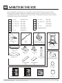
What’s in the box
Prior to installation, verify that you have received all fan contents included with your system by checking
them against the packing list. Materials not included in the fan contents (e.g., Grade 5 hardware, etc.) are the
responsibility of the installer. Notify your product representative or Skyblade Fan Company of any discrepancy
or missing kit contents prior to installing unit.
Wingtip Fence
(x6)
Airfoil
(x6)
VFD Enclosure (x1) &
Strain Relief Bushing (x3)
Control Box (x1) &
Strain Relief Bushing (x1)
Motor & Chassis
(x1)
Upper Yoke
(x1)
Lower Yoke
(x2)
Clamping Plate
(x2)
Control Wire
(x1 - 100’)
Motor Supply Cable
(x1 x 25’)
6 #6 x 5/8” Flat Phil Screw
4 1/2”-13x2-1/2” GR 5 Bolt
4 1/2”-13x3-1/2” GR 5 Bolt
4 1/2”-13x1-1/2” GR 5 Bolt
24 1/2” Flat Washer
12 1/2”-13 Nylock Nut
6 5/16”-24x2” GR 5 Bolt
6 5/16”-24x1-3/4”
GR 5 Bolt
24 5/16”
Flat Washer
12 5/16”-24
Nylock Nut
5 5 Gripple Fasteners
Hardware Packet 1 Hardware Packet 2 Gripple Packet
Airfoil Straight
Bracket (x6)
Airfoil Boomerang
Bracket (x6)

6
SKYBLADE FANS -
Where Form Follows Function
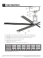
1 Fan Diagram
A. Safety Cable: Used as a redundant safety feature that secures the fan to the mounting structure.
B. Upper Yoke: Secures the fan to the structure and allows the fan to hang in a vertical direction.
C. Extension Bar: Extends the fan from the ceiling to reach optimum operating height.
D. Lower Yoke: Connects the chassis to mounting assembly.
E. Chassis: Housing for the motor and gear reducer
F. Airfoil: Provides air movement.
G. Wingtip Fence: Improves air movement eciency by reducing drag.
Series
STOL STOL STOL STOL STOL STOL
Diameter
12’ / 3.6M 14’ / 4.3M 16’ / 4.9M 18’ / 5.5M 20’ / 6.1M 24’ / 7.3M
Blades
6 6 6 6 6 6
Voltage Input
115 230 460 575 115 230 460 575 115 230 460 575 115 230 460 575 115 230 460 575 115 230 460 575
Model Number Ordering Format: SERIES-DIAMETER-BLADES-INPUT VOLTAGE-PHASE
Sample Model Number: STOL-1649-623-1

SKYBLADE FANS -
Where Form Follows Function 7
2 Important Information
2.1 Skyblade Safety Components
Skyblade fans are designed with redundant safety features to provide protection in the unlikely event of a
catastrophic failure. Follow installation instructions carefully when installing fans.
2.2 Fan Spacing’s and Placement
A standard ceiling fan should be mounted so that the bottom of the fans hub is 38 inches below the bottom of
the beam which it is mounted. Fan blades should be mounted between 10’ and 50’ above the oor with optimum
height between 20’-30’. If desired, extension bars are available to lower the fan if needed. Avoid mounting fans
directly below lights or skylights to avoid a strobe eect caused by the moving blades.
When mounting a fan in an area where objects may be lied or moved into the path of the fan, Skyblade Fans
recommends marking or painting hash lines on the oor to alert personnel of the above movement of the fan.
e area within 15% of the diameter when the fan is at rest is considered “close clearance”. It is extremely
dangerous to mount the fans within “close clearance” of any object or path of object. We strongly recommend
not mounting the fan closer than 15% of its diameter to any object or its path. If this is an issue, mounting
extension bars and smaller fans are available from Skyblade Fans.
2.3 Fire Suppression Systems and Fan Placement
If installing Fans in a location where re sprinklers are in place, do not interfere with their correct operation.
Fans should be located in the center of each sprinkler quadrant and no less than 3 feet below the sprinkler.
Review all codes applicable to sprinkler systems prior to installation; it is the customer’s responsibility to see that
the installation is completed to code and that it is correct.
2.4 Locating Control Panels
Each fan has its own motor control enclosure (MCE). Each MCE must be located no less than 5 feet outside
maximum blade length, and within 25 feet of the fan. Compliance with OSHA requires the lockable service
disconnect on the side of the MCE is within line of sight of the motor.
2.5 Shielded Motor Cable
To minimize electromagnetic interference and stray voltage, each Skyblade fan includes 25 feet of shielded motor
cable, cable glands, and a variable frequency drive with a built-in lter. e shielded motor cable connects the
motor and variable frequency drive. is shielded system reduces the likelihood of broadcasting and receiving
electronic noise which can interfere with radio and other sensitive equipment.
2.6 Check Compliance with Federal, State, and Local Codes
Check all relevant codes to make sure product certications, product listings, and building regulations are met.
Code compliance is the responsibility of the installer.

8
SKYBLADE FANS -
Where Form Follows Function
3 mOUNTING cONSIDERATIONS
3.1 General Mounting
Each type of mounting system requires a specic mounting bracket. Most are available from Skyblade Fans.
Check with the contractor, building owner, or architect to ensure the structure is sound and will support the
weight of the fan before beginning installation. Skyblade Fans provides guidelines for mounting fans; however, it
is the sole responsibility of the building owner and installer to ensure the safety of the mounting system, that the
building structure is sound, and the installation complies with all federal, state, and local codes.
3.2 Weight
A Standard 1-horsepower 16 foot 6-blade fan and mounting assembly weighs about 250 pounds. In inverted-
blade applications designed to blow air upward, there is an additional downward force of about 80 pounds due
to fan thrust. We recommend applying a safety factor of 2 times the stated hanging weight of the fan when
determining the capabilities of the building structure.
3.3 Torque
e maximum torque that must be handed by the mounting system and the building structure will occur at the
fans startup. For a 16 foot fan, maximum potential startup torque is 300 -lbs. Skyblade Fans use a so-start
technology which allows the rpm to ramp up as desired over 60 seconds. e event of this max torque being
applied is unlikely and will only apply due to a failure of the variable frequency drive and its so start technology.
3.4 Safety Cable
A Skyblade fan should never be run without proper installation of Safety Cables. ese are supplied with every
fan. You must install safety cable for warranty to be in eect.
3.5 Guy Wires
While in operation a fan can sway due to minor imbalance or because of wind. Since the mounting system is
capable of swiveling, it will not stop fan movement, so it is important that the guy wires be installed properly.
Proper installation includes the angle and tension of the guy wires. See page 17-18 for more information.
3.6 Universal Mounting Hardware
We recommend mounting the fan to a horizontal structural beam, however, this is not always possible in
buildings with pitched roof construction. For this reason, our universal mounting system is designed to allow the
fan to hang in a level position perpendicular to the ground by rotating the upper yoke 90 degrees.
When cutting or drilling into a wall or ceiling, take care not to damage electrical wiring or other utilities.
Lorsque vous coupez ou percez un mur ou un plafond, prenez garde à ne pas endommager les ls électriques ou
d’autres services publics.
Select a location that is free from obstructions that may interfere with the fan’s operation.
Choisissez un emplacement qui est libre de tout obstacle pouvant interférer avec le fonctionnement du ventilateur.
CAUTION /ATTENTION
!

SKYBLADE FANS -
Where Form Follows Function 9
4 Preparing the Work Site
4.1 Mechanical Installation
A 24’ (7.3m) STOL fan (our largest model) weighs, at maximum, 310 lbs (140kg). A scissor li, or other suitable
means for liing and a minimum of two installation personnel, will be required.
Skyblade Fans can only be hung from an I-beam or angle irons. See installation instructions on the following
page. Do not mount the fan to single purlins, trusses, or bar joists. Consult a structural engineer for installation
methods not covered in the manual.
e fan installation area and path must be free of obstructions such as lights, cables, sprinklers, or other building
structure. We strongly recommend not mounting the fan closer than 15% of its diameter to any object or its path.
Do not install the fan where it will be continuously subjected to high winds (ex. Under a high velocity HVAC
system). Allow a required 2x the fans diameter between the fan and the HVAC (or other air-moving) equipment
when measured from the center of the fan to the equipment.
e spacing between multiple fans should be no less than 2.5x the fans diameter when measured from the center
of the fans.
e mounting structure must be able to withstand the torque which is generated by the fan. A 20’ diameter fan
generates a maximum of nearly 300 -lb (406.7 N-m) of torque during operation.
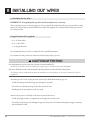
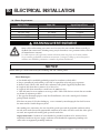
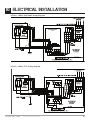
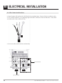
4.2 Electrical Installation
To reduce the risk of electrical shock, wiring should be performed by a qualied electrician. Incorrect assembly
can cause electric shock or damage the motor and controller.
e installation of a Skyblade Fan must comply with the National Electrical Code, ANSI/NFPA 70-1999, and all
local codes.
All unused conductors that share conduit with the AC supply feeds must be grounded on both ends.
If required, a local disconnect should be installed per NEC and all local codes.
Refer to specications on page 24 for appropriate circuit requirements.
Each fan requires dedicated branch circuit protection.
To reduce the risk of injury to persons, install the fan so that the blade(s) is at least 10 feet (3.05 meters) above the
oor.
Pour réduire le risque de blessures, installez le ventilateur de sorte que la lame (s) est d’au moins 10 pieds (3,05
mètres) au-dessus du sol.
CAUTION /ATTENTION
!

10
SKYBLADE FANS -
Where Form Follows Function
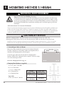
5 mOUNTING Method 1: I-Beam
5.1 Attach Upper Yoke (to I-Beam)
Measure the ange width of the I-beam you are wanting to hang the
fan from. Compare the I-beam ange width to the diagram below to
determine what mounting holes you will require.
Secure the upper yoke to the I-beam with the “Clamping Plate”
hardware shown below. Tighten the bolts to 90 -lb, (122 N-m) using a
3/4” socket and torque wrench.
Proceed to “Hanging the Fan” on pg. 14.
Clamping Plate Hardware (supplied):
a. (4) 1/2“-13x2.5” GR 5 Bolt
b. (8) 1/2” Flat Washer
c. (4) 1/2”-13 Nylock Nut
d. (2) Clamping Plate
e. (2) Clamping Shim
Upper Yoke
13-3/4” (45.7cm) x 8” (20.3cm)
I-Beam
Flange Width
Upper Yoke
Mounting Holes
5” (12.7cm)
8-3/8” (21.2cm)
inner holes
>8-3/8” (21.2cm)
9” (22.8cm)
outer holes
Outer Holes
Inner Holes
Install the “Clamping Shims” only if the thickness of the I-beam ange exceeds 3/8” (1cm). e
mounting holes of the shim are closer to one side than the other. Make sure this side is facing the I-beam.
Installez les cales de serrage que si l’épaisseur de la semelle de la poutre supérieure à 3/8 “(1 cm). Les trous de
xation de la cale sont plus près d’un côté que de l’autre. Assurez-vous que ce côté est confronté à la poutre
CAUTION /ATTENTION
!
Support Directly From Building Structure.
All mounting instructions assume that the building structure from which the fan will be hung
is of sound construction, undamaged, and capable of supporting loads of up to 650 lbs (295 kg).
It is the sole responsibility of the customer to verify that the building’s structure is adequate for
fan installation. Skyblade Fans recommends consulting with a structural engineer prior to fan
installation.
Aider directement à la structure du bâtiment.
Toutes les instructions de montage supposent que la structure du bâtiment à partir de laquelle le ventilateur sera
pendu est de construction solide, en bon état, et capable de supporter des charges de jusqu’à 650 lb (295 kg). Il
est de la seule responsabilité du client de vérier que la structure du bâtiment est susante pour l’installation du
ventilateur. Skyblade fans recommande de consulter un ingénieur en structure avant d’attiser installation.
WARNING/ AVERTISSEMENT
!
!

SKYBLADE FANS -
Where Form Follows Function 11
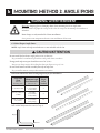
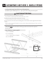
6 mOUNTING Method 2: Angle Irons
6.1 Select Proper Angle Irons:
NOTE: Angle Irons and angle iron hardware are not included with the fan.
Angle Iron
Span
(between
mounting point)
Minimum Angle
Iron Dimensions
(W x H x T)
Qty. of
Angle
Irons
Needed
6’ (1.8m) or less
2.5”(6.4cm)
x 2.5”(6.4cm)
x .25”(.6cm)
2
over 6’ (1.8m) - 8’
(2.4m)
3”(7.6cm)
x 3”(7.6cm)
x .25”(.6cm)
2
over 8’ (2.4m) -
12’ (3.7m)
3”(7.6cm)
x 3”(7.6cm)
x.25”(.6cm)
4*
ickness
Height
Width
6’ (1.8m) or less
over 6’ (1.8m) - 8’ (2.4m)
over 8’ (2.4m) - 12’ (3.7m)
Never use clamping plate or clamping shims when mounting the fan to angle irons!
Ne jamais utiliser la plaque de serrage ou des cales de serrage lors du montage du ventilateur à
cornières!
Beam clamps are only intended for I-beam installations.
Serre-poutres sont uniquement destinées aux installations de faisceaux.
WARNING/ AVERTISSEMENT
!
Do not install the fan from a single purlin, truss, or bar joist.
Ne pas installer le ventilateur à partir d’une seule panne, botte, ou solives.
Unsupported angle iron spans should not exceed 12’ (3.7m).
Non pris en charge travées de fer d’angle ne doit pas dépasser 12 pi (3,7 m).
Do not install motor and hub assembly directly on angle iron.
Ne pas installer moteur et moyeu directement sur cornière.
CAUTION /ATTENTION
!
Follow the table below when selecting angle irons for fan installation.
*2 pairs of angle irons. Pairs should be placed
back to back and fastened in center (see step 2).

12
SKYBLADE FANS -
Where Form Follows Function
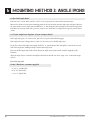
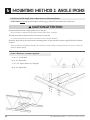
6 mOUNTING Method 2: Angle Irons
6.2 Pre-Drill Angle Irons:
Drill two 9/16” (1.4cm) holes exactly 5-15/32” (13.8 cm) apart in the center of the two angle irons.
Measure the distance between the mounting points of the roof structure that the angle irons will span. Measure
the same distance on the angle irons and drill 9/16” (1.4cm) diameter holes through each end of the angle irons.
Drill holes in two angle irons if the span is 8’ (2.4m) or less. Drill holes in 4 angle irons if span is greater than 8’
(2.4m)
.
6.3. Fasten Angle Irons Together (if span is longer than 8’)
If the angle iron span is 8’ (2.4m) or less, proceed to step 6.4a on the following page.
If the angle iron span is longer than 8’ (2.4m), it is necessary to use double angle irons.
Locate the center of the angle iron length. Drill 9/16” (1.4cm) diameter hole through the center of the vertical
wall of the angle iron. Drilling through a total of four angle irons.
Place two drilled angle irons back to back. Fasten the angle irons together with customer supplied grade 5
hardware.
Align the angle irons to each other and tighten the bolts to 90 -lb (122 N-m) using a 3/4” socket with torque
wrench.
Proceed to step 6.4b.
Grade 5 Hardware (customer supplied)
a. (2) 1/2”-13 GR 5 Bolt
b. (4) 1/2” Flat Washer
c. (2) 1/2” Nylock Nut

SKYBLADE FANS -
Where Form Follows Function 13
6 mOUNTING Method 2: Angle Irons
6.4a Fasten Single Angle Iron to Roof Structure Mounting Points:
If installation requires double angle irons (i.e., span is greater than 8’(2.4m)), proceed to step 6.4b.
ATTENTION: Do not tighten the hardware until the upper yoke has been mounted to the angle irons.
Proceed to step 6.4b.
Grade 5 Hardware (customer supplied):
a. (4) 1/2”-13 GR 5 Bolt
b. (8) 1/2” Flat Washer
c. (4) 2-1/2” Square Washer (see diagram)
d. (4) 1/2” Nylock Nut
Do not install the fan from a single purlin, truss, or bar joist.
Ne pas installer le ventilateur à partir d’une même purlin, botte, ou solives.
e angle irons must be fastened to the roof structure at each end.
Les cornières doivent être attachés à la structure de toit à chaque extrémité.
Fasten the angle irons to the roof structure mounting points at each end with customer-supplied Grade 5 hardware
as shown.
Fixer les cornières aux points de xation de la structure du toit à chaque extrémité fourni par le client 5 e année du
matériel comme indiqué.
CAUTION /ATTENTION
!
2.5”
(6.4 cm)
9/16” Dia.
(1.4 cm)
2.5”
(6.4 cm)

14
SKYBLADE FANS -
Where Form Follows Function
6 mOUNTING Method 2: Angle Irons
6.4b Fasten Double Angle Irons to Roof Structure Mounting Points:
ATTENTION: Do not tighten the hardware until the upper yoke has been mounted to the angle irons.
Grade 5 Hardware (customer supplied):
a. (4) 1/2”-13 GR 5 Bolt
b. (8) 1/2” Flat Washer
c. (4) 2-1/2” Square Washer (see diagram)
d. (4) 1/2” Nylock Nut
Do not install the fan from a single purlin, truss, or bar joist.
Ne pas installer le ventilateur à partir d’une même purlin, botte, ou solives.
e angle irons must be fastened to the roof structure at each end.
Les cornières doivent être attachés à la structure de toit à chaque extrémité.
Fasten the angle irons to the roof structure mounting points at each end with customer-supplied Grade 5 hardware
as shown.
Fixer les cornières aux points de xation de la structure du toit à chaque extrémité fourni par le client 5 e année du
matériel comme indiqué.
CAUTION /ATTENTION
!

SKYBLADE FANS -
Where Form Follows Function 15
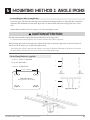
6 mOUNTING Method 2: Angle Irons
6.5 Attach Upper Yoke (to Angle Iron):
Secure the upper yoke directly to the angle irons with the Beam Clamp hardware as depicted below. Consult the
diagrams below for distances between the angle irons. Do not install the fan from a single purlin, truss, or bar
joist.
Tighten bolts to 90 -lb (122 N-m) using a 3/4” socket and torque wrench.
Beam Clamp Hardware (supplied):
a. (4) 1/2”-13x2-1/2” GR 5 Bolt
b. (8) 1/2” Flat Washer
c. (4) 1/2”-13 Nylock Nut
11 1/4: (28.32cm)
Upper Yoke Top View
13 3/4” (34.9cm) x 8” (20.32cm)
a
b
b
c
Upper Yoke Side View
e angle irons should be aligned with the outermost holes of the upper yoke.
Les cornières devraient être alignées avec les trous extérieurs de la culasse supérieur.
Aer attaching upper yoke to the angle irons, tighten all the bolts securing the angle irons to the roof structure to
90 -lb (122 N-m) using a 3/4” socket with torque wrench.
Après l’avoir xée culasse supérieure aux cornières, serrer tous les boulons de xation des cornières à la structure
du toit à 90 lb-pi (122 Nm) avec une “prise 3/4 avec une clé dynamométrique.
CAUTION /ATTENTION
!

16
SKYBLADE FANS -
Where Form Follows Function
d
c
b
a
e
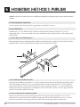
6
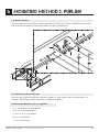
Mounting Method 3: PuRlins
NOTE: Purlin brackets and hardware are available from SkyBlade Fan Company upon request and not included
standard.
6.6 Selecting Proper Angle Irons
Select the proper angle irons based on the requirements stated under section 6.1.
6.7 Pre-Drill Purlins
Drill four 9/16” (1.4 cm) diameter holes centered vertically along the purlin spaced apart 4.5” (11.4 cm)
horizontally and 1.5” (3.8 cm) vertically. ese holes should match up perfectly with those of the purlin bracket
and back plate.
6.8 Attach Brackets and Backing Plates
Purlin mounting brackets and backing plates should be attached using the provided 1/2” grade 5 bolts, washers,
and nylock nuts. A washer should be placed on both sides of the plate for each bolt.
6.9 Pre-Drill Angle Iron Brackets Holes
Your angle iron should be cut to allow 1/2” (1.27 cm) clearance between the end of the angle iron and the purlin
you are mounting to. Drill one 9/16” (1.4 cm) diameter hole centered vertically exactly 1” (2.54 cm) from the
edge on both ends of the vertical wall of the angle iron. Drill a second hole exactly 3” (7.6 cm) inward from the
rst hole on both ends. Repeat for the second angle iron. ese holes will be used to secure the angle iron to the
purlin bracket with the provided hardware.
6.10 Pre-Drill Angle Iron Fan Mounting Holes
Measure the distance between the mounting points that each angle iron will span. Drill two 9/16” (1.4 cm)
diameter holes centered on the bottom wall of each angle iron. e two holes should be spaced 5.5” (13.9 cm)
apart to best match those of the upper yolk. ese holes will attach the upper yolk to the angle iron.

SKYBLADE FANS -
Where Form Follows Function 17
d
a
e
c
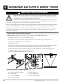
6
Mounting Method 3: PuRlins
6.11 Mount Angle Iron
Attach the angle irons to the brackets using the provided 1/2” grade 5 bolts, washers, and nylock nuts. e angle
irons must be facing outward secured to the outside faces of the purlin brackets.
6.12 Attach Upper Yoke to Angle Iron
Attach the upper yolk to the angle irons using the provided 1/2” grade 5 bolts, washers, and nylock nuts. See
section 6.5 “Attach Upper Yoke (to Angle Iron)” to continue installation.
Purlin Bracket Hardware (per set, supplied):
a. (2) 1/4” Formed Steel Purlin Bracket
b. (2) 1/4” Steel Purlin Backplate
c. (16) 1/2”-13-1 3/4” GR 5 Bolt
d. (16) 1/2” Nylock Nut
e. (32) 1/2” Flat Washer

18
SKYBLADE FANS -
Where Form Follows Function
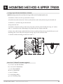
6
Mounting Method 4: Upper Truss
6.13 Upper Open Web Joist Installation (Unistrut)
NOTE: Mounting materials located above the Upper Yolk are NOT included with the fan.
1. Install the 8” at bar over the top chord of the web joist.
2. Install the threaded rod into the 8” at bar, and install the washer and nut atop the threaded rod.
3. Weld the 1/2” nylock nut atop the threaded rod.
4. Repeat for all 8 rods.
5. Install the Unistrut with open sides facing up and the 8” at bar beneath them onto threaded rods using 1/2”
washers and 1/2”-13 nylock nuts thus sandwiching the top chord of the joist. Torque to 90 /lbs.
6. Route safety cable around the beam assembly and top chord of the joist at each mounting point. Secure
safety cable using two wire rope clips on each cable.
7. Continue with fan mounting procedures in section 7.0.
Weight calculations must be done to select the proper size unistrut. Failure to do so may result in
damages to the fan and building or even personal harm. Skyblade Fan Company is NOT liable for
any damages or injury resulting from improper installation.
Calculs de masse doit être fait pour sélectionner le unistrut de taille appropriée. Défaut de le faire peut
aboutir à dommages au ventilateur et de bâtiment ou même un préjudice personnel. Skyblade Fan Company est pas
responsable de tout dommage ou blessure résultant d’une mauvaise installation.
It is the sole responsibility of the customer to verify that the building’s structure and mounting assembly is adequate
for fan installation. Skyblade Fans recommends consulting with a structural engineer prior to fan installation.
Il est de la seule responsabilité du client de vérier que la structure du bâtiment et ensemble de montage est adéquat
pour l’installation du ventilateur. Ventilateurs Skyblade recommande de consulter un ingénieur en structure avant
l’installation du ventilateur.
WARNING /AVERTISSEMENT
!
!
Parts List “Unistrut” (customer supplied):
a. (4) 8”x 9”x 1/4” Flat Steel Plates
b. (2) Unistrut Bars
c. (8) 1/2” readed Rods
d. (16) 1/2” Nylock Nuts
a
b
c
e
d
f
e. (16) 1/2” Washers
f. (2) Steel Safety Cables
g. (4) 1/8” Wire Rope Clips
Side View

SKYBLADE FANS -
Where Form Follows Function 19
e
a
6
Mounting Method 4: Upper Truss
6.14 Upper Open Web Joist Installation (C Channel)
NOTE: Mounting materials located above the Upper Yolk are NOT included with the fan.
1. Install the 8” at bar over the top chord of the web joist.
2. Install the threaded rod into the 8” at bar, and install the washer and nylock nut atop the threaded rod.
3. Weld the 1/2” nylock nut atop the threaded rod.
4. Repeat for all 8 rods.
5. Install the C Channels with open sides facing away from each other onto threaded rods using 1/2” washers
and 1/2”-13 nylock nuts thus sandwiching the top chord of the joist. Torque to 90 /lbs.
6. Route safety cable through a whole drilled in the beam assembly and above the top chord of the joist at each
mounting point. Secure safety cable using two wire rope clips on each end of the cable.
7. Continue with fan mounting procedures in section 7.1.
Parts List “C Channel”(customer supplied):
a. (2) 8”x 9”x 1/4” Flat Steel Plates
b. (2) 1/4” Steel C Channel Bars
c. (8) 1/2” readed Rods
d. (16) 1/2” Nylock Nuts
e. (16) 1/2” Washers
f. (2) Steel Safety Cables
g. (4) 1/8” Wire Rope Clips
b
c
d
f
Side View

20
SKYBLADE FANS -
Where Form Follows Function
c
b
a
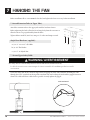
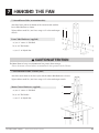
7 Hanging The Fan
Before installation all set screws must be checked, and tightened where necessary, before installation.
7.1 Attach Extension Tube (to Upper Yoke):
Attach the extension tube to the upper yoke with the hardware shown.
Before tightening the bolts, allow the fan to hang freely from the structure to
allow the fan to rest perpendicularly from the oor.
Tighten bolts to 90 -lb (122 N-m) using a 3/4” socket and torque wrench.
Single Pivot Hardware (supplied):
a. (2) 1/2”-13 x 3-1/2” GR 5 Bolt
b. (4) 1/2” Flat Washer
c. (2) 1/2”-13 Nylock Nut
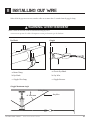
7.2 Secure Upper Safety Cable:
Secure the safety cable to the I-beam or angle iron by wrapping the safety cable around it, threading the cable
through the 17/32” open hole on the top of the extension tube, and securing the ends with the gripple fastener as
shown. e cable must have as little slack as possible. Securely tighten the gripple.
Cable End Detail
e safety cable is a critical safety feature of the fan and must be installed correctly.
Le câble de sécurité est une caractéristique de sécurité essentielle de la souante qui doit être installé
correctement.
WARNING/ AVERTISSEMENT
!
La page est en cours de chargement...
La page est en cours de chargement...
La page est en cours de chargement...
La page est en cours de chargement...
La page est en cours de chargement...
La page est en cours de chargement...
La page est en cours de chargement...
La page est en cours de chargement...
La page est en cours de chargement...
La page est en cours de chargement...
La page est en cours de chargement...
La page est en cours de chargement...
La page est en cours de chargement...
La page est en cours de chargement...
La page est en cours de chargement...
La page est en cours de chargement...
La page est en cours de chargement...
La page est en cours de chargement...
La page est en cours de chargement...
La page est en cours de chargement...
La page est en cours de chargement...
La page est en cours de chargement...
La page est en cours de chargement...
La page est en cours de chargement...
-
 1
1
-
 2
2
-
 3
3
-
 4
4
-
 5
5
-
 6
6
-
 7
7
-
 8
8
-
 9
9
-
 10
10
-
 11
11
-
 12
12
-
 13
13
-
 14
14
-
 15
15
-
 16
16
-
 17
17
-
 18
18
-
 19
19
-
 20
20
-
 21
21
-
 22
22
-
 23
23
-
 24
24
-
 25
25
-
 26
26
-
 27
27
-
 28
28
-
 29
29
-
 30
30
-
 31
31
-
 32
32
-
 33
33
-
 34
34
-
 35
35
-
 36
36
-
 37
37
-
 38
38
-
 39
39
-
 40
40
-
 41
41
-
 42
42
-
 43
43
-
 44
44


Skyblade STOL Series Guide d'installation
- Catégorie
- Ventilateurs ménagers
- Taper
- Guide d'installation
dans d''autres langues
Autres documents
-
 Backyard Discovery 1802513com Guide d'installation
-
Big Ass Fans ShopFan/BA 4900 Guide d'installation
-
-
-
-
 Zoo Fans H30 Guide d'installation
-
-
-
-

