
TLP Pro 525T, 725T, and 1025T Series • Setup Guide
Overview
The TLP Pro 525 Series are 5-inch tabletop capacitive touchscreens with a resolution of 800x480 and 24-bit color depth.
The TLP Pro 725T Series are 7-inch tabletop capacitive touchscreens with a resolution of 1024x600 and 24-bit color depth.
The TLP Pro 1025T Series are 10-inch tabletop capacitive touchscreens with a resolution of 1280x800 and 24-bit color depth.
All these models can be placed on any convenient at surface.
This guide provides instructions for experienced installers to install these touchpanels. For complete instructions, see the
TLPPro 525, 725, and 1025 Series User Guide, at www.extron.com.
Setup Checklist
Get Ready
Download and install the latest version of the following software:
GUI Designer — for designing layouts for Extron TouchLink
®
Pro touchpanels and third party touch interfaces
Global Configurator
®
Professional or Global Configurator Plus — for setting up and conguring the control processor
and touchpanel
Toolbelt — provides device discovery, device information, rmware updates, and conguration of network settings,
system utilities, and user management for TouchLink Pro devices
Global Scripter
®
— provides an integrated development environment for Extron control systems programming
NOTE: All four software programs are available from www.extron.com.
Obtain the following network information from your network administrator:
DHCP status (on or off). If DHCP is off, you must also obtain:
IP address Subnet mask Gateway
Username — This can be either admin or user.
Password — By default this is extron (for either admin or user).
Make a note of the touchpanel MAC address.
Mount and Cable All Devices
ATTENTION:
• Do not power on the touchpanels until you have read the ATTENTION in the “Base” section of the TLPPro 525, 725,
and 1025 Series User Guide.
• Ne branchez pas les écrans tactiles avant d’avoir lu la mise en garde dans la section «Base » du TLPPro 525, 725,
and 1025 Series User Guide.
Mount the units. There are several mounting options for TouchLink Pro touchpanels (see Mounting on the next page).
Connect the touchpanel to a Power over Ethernet injector (not provided). Extron recommends the XTP PI 100 power injector,
which must be purchased separately.
Connect the power injector to the LAN and power it on.
Set up the Touchpanels for Network Communication
Connect the PC that you are using for setup, the control processor, and touchpanel to the same Ethernet subnetwork.
Use the Setup Menu (see page 4) or Toolbelt to set the DHCP status and, if necessary, the IP address, subnet mask,
gateway, and related settings for the touchpanel.
Configure the Touchpanels
Create a graphical user interface with GUI Designer (see GUI Designer Help File for step-by-step instructions).
Associate functions with the graphical user interface features by conguring (see the Global Configurator Help File) or
programming (see the Global Scripter Help File) the system. Global Scripter provides an Extron-exclusive Python library
(ControlScript
®
) and Global Scripter modules to get you started.
1
Product Category
IMPORTANT:
Go to for the
complete user guide and installation
instructions before connecting the
product to the power source.
www.extron.com

Mounting
The base allows these touchpanels to be placed on any suitable at surface.
For additional security, the touchpanels can be attached to a table or desktop.
1. Connect an Ethernet cable to the LAN/PoE input (see figure 3,
F
, on the next page) and run the cable through the cable
guide (
D
).
2. Drill two holes through the desktop from underneath, 3.07" (78 mm) apart.
3. Attach the touchpanel with two #8-32 screws through the desktop from underneath into the two mounting holes in the base
of the unit (
A
).
The touchpanels can also be mounted with the optional Extron SMA-2 swivel mount adapter, which allows them to be secured
to the table and swivel up to 180° in either direction. Attach the SMA-2 to the mounting holes in the base (
A
) and follow the
instructions in the SMA-2 Swivel Mount Adapter Kit User Guide.
Front Panel Features
Figure 1 shows the TLP Pro 725T Series front panel. The front panels of the TLP Pro 525T and TLP Pro 1025T Series are very
similar.
BBCC
E
E
D
D
A
A
BB
Figure 1. TLP Pro 725T Front Panel
A
LCD touchscreen
z TLP Pro 525T Series — 5-inch, 800x480 resolution touchscreen
z TLP Pro 725T Series — 7-inch, 1024x600 resolution touchscreen
z TLP Pro 1025T Series — 10-inch, 1280x800 resolution touchscreen
The touchscreen is made with Corning Gorilla Glass, which is stronger and more scratch-resistant than standard glass, while
maintaining touch sensitivity, color saturation, and brightness.
B
Motion sensor (2) — Detects motion between three to ve feet from the touchpanel, and at least 15° from the center axis.
z When no motion has been detected for a user-dened period of time, the touchpanel enters sleep mode.
z When motion is detected by the sensor, the screen display is restored and active.
C
Communication LED — Shows the conguration and connection status of the touchpanel:
z Unlit during normal operation (the touchpanel is congured and connected to an IP Link Pro control processor).
z Blinks red if the touchpanel has been congured but is not connected to an IP Link Pro control processor.
z Solidly lit if the touchpanel has not been congured.
The indicator can be toggled between enabled and disabled, using the Setup Menu (see page 4).
D
Light sensor — Monitors ambient light level and adjusts screen brightness, based on the settings congured using the
Setup Menu.
E
Status light — Can be programmed to provide system feedback:
z Light red or green
z Blink or light continuously
For information about conguring or programming this light, see the Global Configurator Help File or the Global Scripter Help
File.
2
TLP Pro 525T, 725T, and 1025T Series • Setup Guide (Continued)

Rear Panel Features
AA
BB
CC
Figure 2. TLP Pro 725T Rear Panel
Figure 2 shows the TLP Pro 725T Series rear panel. The
TLP Pro 525T and 1025T Series rear panels are very similar.
A
Status light — Can be programmed to provide system
feedback:
z Light red or green
z Blink or light continuously
For information about conguring or programming this light,
see the Global Configurator Help File or the Global Scripter
Help File.
B
USB-A port — Compatible with USB 2.0. The port is
concealed behind a plastic cover, which can be removed
with a small, at-bladed screwdriver.
C
Cable guide — The LAN cable is inserted through this hole
at the back of the base (see LAN/PoE connector below).
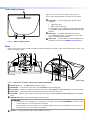
Base
Figure 3 shows the TLP Pro 525T and 725T Series models from the bottom. The base of the TLP Pro 1025T Series models is very
similar to the TLP Pro 725T.
FFAABBDDE
EG
GCC AA
TLP Pr
o 725T
FFDD
BBCCEEGGAA TLP Pro 525T
Figure 3. Base Panels of TLP Pro 725T (Left) and TLP Pro 525T (Right)
A
Mounting holes (2) — See Mounting on the previous page.
B
Menu button — Activates the Setup menu (see Setup Menu on the following page).
C
Reset button — Initiates one of three reset modes for the unit (see Reset Modes: a Brief Summary on the following page).
D
Cable guide — The LAN/PoE cable is inserted through this hole at the back of the base.
E
Reset LED — Indicates power status and reset status of the device (see Reset Modes: a Brief Summary on the following
page).
F
LAN/PoE Connector — Attach the LAN cable to this RJ-45 port.
ATTENTION:
• Do not power on the touchpanels or control processors until you have read the ATTENTION in the “Base” section
of the TLP Pro 525, 725, and 1025 Series User Guide.
• Ne branchez pas les écrans tactiles ou les contrôleurs avant d’avoir lu la mise en garde dans la section «Base »
du TLP Pro 525, 725, and 1025 Series User Guide.
G
Speaker — A single speaker provides audible feedback for the user.
3
Product Category

TLP Pro 525T, 725T, and 1025T Series • Setup Guide (Continued)
100-240V
~
50-60Hz
0.4A MAX
XTP
PWR
XTP PWR
To network switchTo touchpanel
1
12
2
3
3
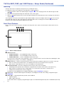
Figure 4. Connecting to a Power Injector
Connecting the Power injector
The power injector must be purchased separately. Figure 4 shows the Extron
XTP PI 100. Your power injector may look different.
Connect a straight-through Ethernet cable from the power injector to a
switch or router (see gure 4,
1
). This cable carries network information
from the switch or router to the power supply input. A second straight-
through cable (
2
) carries the network information and 48VDC from the
power injector to the touchpanel LAN/PoE connector (see figure 3,
F
, on
the previous page). Connect the IEC power cord to a convenient 100 VAC to
240 VAC, 50-60 Hz power source (
3
).
Reset Modes: a Brief Summary
The TLP Pro 525T, 725T, and 1025T Series touchpanels offer the following reset modes:
• Use Factory Firmware: Use this mode with Toolbelt software to replace rmware in the event of conicts arising from
uploading a rmware update.
Press and hold the Reset button (see
C
) while applying power to the unit.
• Reset All IP Settings: Use this mode to reset all network settings without affecting user-loaded les.
Press and hold the Reset button until the Reset LED (
E
) blinks twice (about 6 seconds).
Release and momentarily press the Reset button again.
• Reset to Factory Defaults: Use this mode to return the touchpanel to factory default settings.
Press and hold the Reset button until the Reset LED blinks three times (about 9 seconds).
Release and momentarily press the Reset button again.
• Enable or Disable the
DHCP Client:
Use this mode to toggle between DHCP enabled and DHCP disabled.
Press the Reset button ve times, consecutively. After the fth press, do not press the button
again within 3 seconds. If DHCP was enabled, it is now disabled and the Reset LED blinks three
times. If DHCP was disabled, it is now enabled and the Reset LED blinks six times.
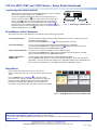
Setup Menu
Figure 5 shows the Setup menu Status screen for the
TLP Pro 725T model. The menu screens for all other models are very
similar.
Press the Menu button (see figure 3,
B
) to open the Setup
menu. Select any of the ve available screens (Status, Network,
Display, Audio, and Advanced) by pressing the appropriate
button in the navigation bar at the top of the screen (for more
information, see the TLP Pro 525, 725, and 1025 Series User Guide).
Info
Model: TLP Pro 725T
Part Number:60-1562-02
Firmware
Version:
1.02.0000.b003
PoE: Active
Network
IP Address:
DHCP:
Host Name:
Off
192.168.254.251
TLI-AB-CD-EF
Display
Resolution:
Project:
Sleep Timer:
1024x600
1024x600
5 Minutes
Audio
Master Volume:
Master Mute: Off
100
Status
Display
Audio
Advanced
Exit
Network
Advanced
Controller IP: 192.168.254.250
Project Size: 1/197 MB
Bootloader
Version:
1.03.0000
Figure 5. Setup Menu: Status Screen for TLP Pro 725T
4
68-2831-54 Rev. A
01 19
For information on safety guidelines, regulatory compliances, EMI/EMF compatibility, accessibility, and related topics, see the
Extron Safety and Regulatory Compliance Guide on the Extron website.
For information about replacing and disposing of batteries, see the TLP Pro 525, 725, and 1025 Series User Guide at
www.extron.com.
© 2019 Extron Electronics — All rights reserved. www.extron.com
All trademarks mentioned are the property of their respective owners.
Worldwide Headquarters: Extron USA West, 1025 E. Ball Road, Anaheim, CA 92805, 800.633.9876
-
 1
1
-
 2
2
-
 3
3
-
 4
4


Extron TLP Pro 525T Manuel utilisateur
- Taper
- Manuel utilisateur
- Ce manuel convient également à
dans d''autres langues
- English: Extron TLP Pro 525T User manual
Documents connexes
-
Extron TLP Pro 525T Manuel utilisateur
-
-
Extron TLI Pro 101 Manuel utilisateur
-
-
-
Extron TLI Pro 201 Manuel utilisateur
-
-
Extron TLP Pro 725M Manuel utilisateur
-
Extron TLP Pro 525C Manuel utilisateur
-