

www.welbilt.com 800-225-9916 2
Table of Contents
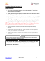
General Safety Information ........................................................................................................ 3
Receiving Inspection ................................................................................................................... 4
Locating and Mounting Condensing Units ...............................................................................4-5
Condensing Unit Specifications ................................................................................................... 6
Locating and Mounting Evaporator Coils .................................................................................7-8
Evaporator Unit Specifications .................................................................................................... 8
Wiring ......................................................................................................................................... 9
Piping ..................................................................................................................................... 9-14
Leak Test ............................................................................................................................. 15-16
Evacuation ........................................................................................................................... 16-17
Refrigerant Charging ................................................................................................................. 17
Suction/Liquid Line Sizing Chart ............................................................................................... 18
Operational Start-Up ................................................................................................................ 19
Navigation Using The Basic Display .......................................................................................... 19
Introduction To ArcticFox Smart Access............................................................................... 20-26
Setting Up Email/Text Alerts ..................................................................................................... 27
Maintenance ....................................................................................................................... 28-29
Evaporator Troubleshooting ...................................................................................................... 29
Condensing Unit Troubleshooting ........................................................................................ 30-31
System Start-Up Data Sheet ................................................................................................ 32-35
Warranty Information................................................................................................................. 36

www.welbilt.com 800-225-9916 3
General Safety Information
Read this manual carefully before beginning the installation and operation of the
refrigeration system. Special attention is required to all sections identified with the
following warning and caution notices provided in both English and French languages:
WARNING
Text in a Warning box alerts you to a potential personal injury situation. Read each
Warning statement before proceeding and work carefully.
AVERTISSEMENT
Le texte qui figure dans les encadrés d’avertissement vous alerte d’une
situation pouvant potentiellement causer des blessures. Lire chaque
déclaration d’avertissement avant de procéder et travailler prudemment.
CAUTION
Text in a Caution box alerts you to a situation in which you could damage the
refrigeration system. Read each Caution statement before proceeding and work
carefully.
MISE EN GARDE
Le texte qui figure dans les encadrés de mise en garde vous alerte d’une
situation dans laquelle le système de réfrigération pourrait subir des
dommages. Lire chaque déclaration de mise en garde avant de procéder et
travailler prudemment.
Disregarding these special notices may result in personal injury and/or damage to the
refrigeration system.
Safety Notices:
Installation and maintenance/servicing are to be performed only by trained and
qualified personnel familiar with commercial refrigeration systems.
Ensure that all field wiring conforms to the equipment requirements and all
applicable local and national codes.
Disconnect all power sources before servicing the refrigeration equipment.
Sheet metal and coil surfaces have sharp edges. Use appropriate protective
gloves to prevent injury.
Use appropriate eye protection during installation and servicing.

www.welbilt.com 800-225-9916 4
Receiving Inspection
Check the shipment carefully and compare to the bill of lading. Account for all items
listed and inspect each container for damage. Carefully inspect for any concealed
damage. Report any shortages or damages to the carrier, note on the bill of lading, and
file a freight claim.
Damaged material cannot be returned to the manufacturer without prior approval. A
Return Material Authorization (RMA) must be obtained. Contact a sales representative
at 800-826-7036.
Locating and Mounting Condensing Unit
General Guidelines:
Check the selected installation location to ensure that racks, braces, flooring,
foundations, etc. are adequate to support the condensing unit weight.
The installation location is clean, dry, and level.
Locate away from corrosive and noise sensitive atmospheres.
Use the condensing unit skid and base when moving the unit. Do not remove
unit from skid until the unit is moved to the mounting location.
Mount the condensing unit base to pads or structural rails using properly sized
bolts through the unit base. Center of condensing unit needs to be properly
supported.
WARNING
Do not lift the condensing unit by the refrigerant tubing or components. These
features will not support the condensing unit weight. Injury and unit damage may
occur!
AVERTISSEMENT
Ne pas soulever le groupe compresseur-condenseur par les tubes ou les
composants du réfrigérant. Ces éléments ne supporteront pas le poids du
groupe compresseur-condenseur. Cela pourrait entraîner des blessures et
des dommages à l’appareil!

www.welbilt.com 800-225-9916 5
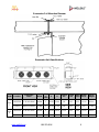
Clearance Requirements:
Locate where there is a sufficient and unrestricted supply of clean ambient air.
Locate where this is adequate space for the removal of the heated discharged air
from the condensing unit area.
Do not position multiple units so that discharge air from one unit is blowing into
the condenser inlet air of the other unit.
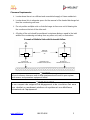
All sides of the unit should be positioned a minimum distance equal to the total
width of the condensing unit away from any other unit, wall, or obstruction.
Example of Multiple Units with Horizontal Airflow
CAUTION
Failure to observe clearance and air flow requirements will result in poor system
performance and premature equipment failure!
MISE EN GARDE
Le non-respect des exigences de dégagement et de circulation d’air aura
pour résultat un rendement médiocre du système et une défaillance
prématurée de l’équipement!
BUILDING WALL
(VIEWED FROM ABOVE)
AIR
FLOW
AIR
FLOW
MINIMUM
DISTANCE
24”
INTAKE AIR
MINIMUM DISTANCE 24”
24”
INTAKE AIR
MINIMUM DISTANCE 24”
24”

www.welbilt.com 800-225-9916 6
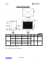
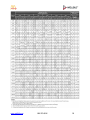
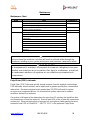
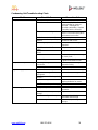
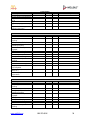
Condensing Unit Specifications
Model Location Compressor Voltage HP MCA MOP
Approx.
Weight
MAC 7
FREEZER ZF13K4E-TF5 208-230/3/60 4.5
31.3 40 660 lbs
COOLER CF04K6E-TF5 208-230/3/60 1.5
MAC 8
FREEZER ZF15K4E-TF5 208-230/3/60 5.5
38.8 50 660 lbs
COOLER CF04K6E-TF5 208-230/3/60 1.5
MCA – Minimum Circuit Ampacity.
MOP – Maximum Overcurrent Protection.

www.welbilt.com 800-225-9916 7
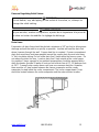
Locating and Mounting Evaporator Coil
General Guidelines:
Do not place the evaporator above or close to door openings. This will help
prevent potential icing problems.
Allow a minimum clearance equal to or greater than the coil height on all sides of
the coil for proper air flow and service access.
Use the evaporator coil for a template to locate and drill the mounting holes (1/2”
diameter).
Place a 1” and a 1-5/8” washer on each nylon bolt and insert through the drilled
mounting holes in the ceiling from the exterior of the walk-in ceiling panel.
NOTE: Nylon bolts are supplied to prevent thermal transfer between the exterior
of the walk-in and the interior of the walk-in. Do not use metal bolts.
Lift the evaporator coil until the nylon bolts extend through the mounting
brackets.
Install washers and secure with nuts. Tighten until the coil is firm against the
ceiling. The evaporator coil must be level.
Additional information is available in the installation manual supplied with the
evaporator.
CAUTION
Failure to observe clearance and air flow requirements will result in poor system
performance and premature equipment failure!
MISE EN GARDE
Le non-respect des exigences de dégagement et de circulation d’air aura
pour résultat un rendement médiocre du système et une défaillance
prématurée de l’équipement!

www.welbilt.com 800-225-9916 8
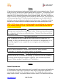
Evaporator Coil Mounting Diagram
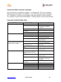
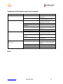
Evaporator Unit Specifications
Model Location
Evaporator
Model
BTUH
No.
of
Fans
A B
Suction
OD
Liquid
OD
Motor
Amps
Heater
Amps
Approx.
Weight
MAC
7
FREEZER EL36-140-2MAC 14,000 3 63.50 55.00 7/8" 3/8" 1.35 13.00 115 lbs
COOLER AM28-134-2MAC 13,400 2 45.50 37.00 7/8" 3/8" 0.90 n/a 77 lbs
MAC
8
FREEZER EL46-185-2MAC 18,500 4 81.50 36.50 1-1/8" 3/8" 1.80 13.00 155 lbs
COOLER
AM28-134-2MAC
13,400
2
45.50
37.00
7/8"
3/8"
0.90
n/a
77 lbs

www.welbilt.com 800-225-9916 9
Wiring
All electrical connections and routing must comply with local and national codes. Do not
modify the factory installed wiring without written factory approval. The field wiring must
enter through the knockouts provided. Refer to the nameplate on the condensing or
evaporator coil to determine the proper electrical power supply. Wire type should be of
copper conductor only and properly sized to handle the electrical load. The unit and coil
must be properly grounded. Condensing unit wiring diagrams are located inside this
installation manual and attached inside the electrical box cover. Evaporator coil wiring
diagrams are located inside this installation manual and inside the evaporator cover.
NOTE: CAT-5 cables, which are included, need to be routed from the evaporators
to the network router for access to the internet. Please contact the end user for
proper connection point.
WARNING
All wiring must comply with local and national codes. Wiring must be performed only
by a refrigeration technician or certified electrician. Failure to follow these guidelines
may result in injury!
AVERTISSEMENT
Tout le câblage doit être conforme aux codes locaux et nationaux. Le
câblage ne doit être effectué que par un technicien en réfrigération ou un
électricien agréé. Le non-respect de ces consignes peut entraîner des
blessures!
CAUTION
Check all wiring connections, including factory terminals, before operation.
Connections can become loose during shipment and installation.
MISE EN GARDE
Vérifier toutes les connexions de câblage, y compris les bornes installées
en usine, avant de faire fonctionner l’appareil. Les connexions peuvent
devenir lâches pendant l’expédition et l’installation.
Piping
General Requirements:
All refrigeration piping and components are to be installed in accordance with applicable
local and national codes and in conformance with industry refrigeration guidelines to
ensure proper operation of the refrigeration system. Only refrigeration grade copper
tubing should be used. Long radius elbows should be used. Short radius elbows have

www.welbilt.com 800-225-9916 10
points of excessive stress concentration and are subject to breaking at these points, do
not use short radius elbows. Suction lines must be insulated with a minimum ¾” thick
insulation tubing to reduce heat pick-up.
Cleanliness:
Condensing units and evaporator coils are cleaned and dehydrated at the factory. The
condensing unit must remain closed and pressurized until the piping is complete and
final connections are ready to be made.
CAUTION
The maximum air exposure for dehydrated condensing units is 15 minutes. Systems
exposed longer than 15 minutes must have the compressor oil and drier filter
replaced. Leaving a system exposed to the atmosphere for more than 15 minutes
can result in premature system failure.
MISE EN GARDE
L’exposition maximale à l’air des groupes compresseurs-condenseurs
déshydratés est de 15 minutes. L’huile du compresseur et le filtre du
dessiccateur doivent être remplacés sur les systèmes qui ont été exposés à
l’air pendant plus de 15 minutes. L’exposition d’un système à l’atmosphère
pendant plus de 15 minutes peut avoir pour résultat une défaillance
prématurée du système.
Do not remove base mount valve covers until work is ready to be performed. Ensure
that all refrigeration tubing is clean and dry prior to installation. Use only tubing cutters
when trimming tubing to the proper length. Do not use saws to cut tubing.
CAUTION
The use of saws to cut tubing can contaminate the system with copper chips causing
premature system failure.
MISE EN GARDE
L’utilisation de scies pour couper le tubage peut contaminer le système par
des copeaux de cuivre et causer une défaillance prématurée du système.
Brazing joints require a dry inert gas, typically nitrogen, be passed through the lines at a
low pressure to prevent scaling and oxidation. Use only silver solder brazing alloys.
Minimize the amount of flux to prevent internal contamination. Flux only the male
portion of the joint. Thoroughly clean fluxed joints after brazing.

www.welbilt.com 800-225-9916 11
CAUTION
Dry inert gas must be passed through the system while brazing to prevent scaling and
oxidation. Scaling and oxides can clog refrigeration components resulting in system
failure.
MISE EN GARDE
Le gaz sec inerte doit passer par le système pendant le brasage afin de
prévenir l’entartrage et l’oxydation. Le tartre et les oxydes peuvent
bloquer les éléments de réfrigération et causer une défaillance du système.
Pipe Supports:
All tubing should be supported in a least two locations (near the end of each tubing run).
Long runs will require additional support. As a guide, support 3/8” to 7/8” pipe every five
feet, 1-1/8” to 1-3/8” every seven feet, and 1-5/8” to 2-1/8” every ten feet. Do not leave
a corner unsupported when changing directions. Place supports within 2 feet of each
direction change. Piping that is attached to a vibrating object (such as a compressor or
compressor base) must be supported in a manner that will not restrict the movement of
the vibrating object. Rigid mounting will fatigue the tubing causing refrigerant leaks.
Oil Traps:
To ensure proper oil return to the compressor, a P-type oil trap should be installed at
the base of each suction riser of four feet or more. The suction trap must be the same
size as the suction line. Additional traps are necessary for long vertical risers. Add a
trap for each length of pipe (approximately 20 feet) to insure proper oil return. Suction
lines must slope ¼” per 10 feet toward the compressor. Install a suction line trap at the
evaporator outlet if the suction line rises to a point higher than the connection on the
evaporator.
CAUTION
Failure to properly install oil traps can prevent sufficient oil return to the compressor
resulting in premature compressor failure.
MISE EN GARDE
L’installation incorrecte des siphons d’huile peut empêcher un retour
d’huile suffisant au compresseur, entraînant une défaillance prématurée du
compresseur.

www.welbilt.com 800-225-9916 12
Pressure Regulating-Relief Valves:
WARNING
Do not defeat, cap, add piping to the outlet of the valve, or, attempt to
change the relief setting.
AVERTISSEMENT
Ne pas annuler, mettre un capuchon, ajouter de la tuyauterie à la prise de
la valve ou tenter de modifier le réglage de décharge.
Drain Lines:
Evaporator coil drain lines should be pitched a minimum of 1/2” per foot to allow proper
drainage and exit the walk-in as quickly as possible. Insulate and seal the drain line
where it passes through the wall. Copper drain line is required. Freezer compartment
drain lines must have heat tape wrapped around the copper drain line and must have
¾” thick insulation tubing. Do not locate drain line P-traps within the freezer space. Do
not reduce the drain line size. Locate a drain line P-trap outside of the cooler space.
Any outdoor P-traps exposed to low ambient temperatures should be wrapped with a
drain line heater (provide 20 watts of heat per foot of drain line at 0°F, 30 watts per foot
at -20°F. Freezer/cooler combo boxes can have one common drain line. However,
there must be a P-trap located between the freezer evaporator and the cooler
evaporator located inside the cooler compartment. The cooler compartment P-trap
should be located between the cooler evaporator and the external drain location.

www.welbilt.com 800-225-9916 13
Pre-Charged lines and Quick Connects:
Route the suction and liquid line sets between the condensing unit and evaporator coil
following the piping guidelines identified in this manual. Remove the dust caps from the
quick connect fittings and verify that the o-rings are intact. Wipe the coupling seals and
threaded surfaces with a clean cloth to prevent contamination. Lubricate the threads
and o-rings with Polyol Ester oil. Thread the coupling halves together by hand to
ensure proper thread mating. Tighten with a wrench until the coupling bodies “bottom”
or until there is definite resistance. Tighten an additional ¼ turn to ensure proper brass-
to-brass seating. Once the system is opened and pressurized, check each fitting for
refrigerant leaks. If a leak is detected, tighten until the leak stops.
WARNING
Do not loosen and disconnect the quick connect fittings before reclaiming the
refrigerant and depressurizing the system. Disconnecting a pressurized system can
result in injury!

www.welbilt.com 800-225-9916 14
Pre-Charged lines and Quick Connects (continued):
AVERTISSEMENT
Ne pas desserrer et désaccoupler les raccords rapides avant de récupérer
le réfrigérant et de dépressuriser le système. La déconnexion d’un système
sous pression peut entraîner des blessures!
CAUTION
Quick connects are for one time use only. Once disconnected, the coupling cannot
be re-used. Refrigerant leaks will occur if the couplings are re-used resulting in poor
system performance.
MISE EN GARDE
Les raccords rapides ne sont prévus que pour un seul usage. Une fois
désaccouplés, ils ne peuvent plus être utilisés de nouveau. Des pertes de
réfrigérant se produiront si les raccords sont réutilisés, ayant pour résultat
un rendement médiocre du système.
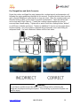
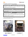
Excess line set length should never be allowed to coil in the vertical position. Excess
line length should be laid flat on its side.

www.welbilt.com 800-225-9916 15
Leak Testing
After all connections are complete the refrigeration system must be tested for leaks.
Failure to perform a leak test can result in unsatisfactory system performance,
additional servicing and service costs, and possible system failure. Leak test should be
performed using an electronic leak detector. All joints and components, both factory
and field installed, should be thoroughly inspected for leaks. The system installation
must be leak free!
Leak Testing “PR” model systems:
Open both the liquid and suction service valves.
Ensure the solenoid valve is energized and open.
Add 50 psi refrigerant, then pressurize with dry nitrogen to the low side test
pressure identified on the unit rating label.
Allow thirty minutes for refrigerant to reach all parts of the system.
Check all joints and components with an electronic leak detector.
Leak Testing “PC” model systems:
Leave the service valves closed, the condensing unit is charged with refrigerant.
Ensure the solenoid valve is energized and open.
Add 50 psi refrigerant, then pressurize with dry nitrogen to the low side test
pressure identified on the unit rating label.
Allow thirty minutes for refrigerant to reach all parts of the system.
Check all joints and components with an electronic leak detector.
Leak Testing “PCL” model systems:
Open both the liquid and suction service valves.
Ensure the solenoid valve is energized and open.
Allow thirty minutes for refrigerant to reach all parts of the system.
Check all joints and components with an electronic leak detector.
If a leak is detected, relieve the pressure and/or reclaim the refrigerant and repair the
leak. If additional brazing is required, pass a dry inert gas (nitrogen) through the system
to prevent contamination. Reference page 12 of this manual for leaks located at quick
connects couplings. Retest the system as outlined above until no leaks are detected.
CAUTION
If a braze joint is detected leaking, dry inert gas must be passed through the system
while repairing the joint to prevent scaling and oxidation. Scaling and oxides can clog
refrigeration components resulting in system failure.
MISE EN GARDE
Si une fuite d’un joint de brasage a été détectée, le gaz inerte doit passer
par le système lors de la réparation du joint afin de prévenir l’entartrage et

www.welbilt.com 800-225-9916 16
l’oxydation du système. Le tartre et les oxydes peuvent bloquer les
éléments de réfrigération et causer une défaillance du système.
CAUTION
Always use the system specified refrigerant when pressuring to perform a leak test.
MISE EN GARDE
Utiliser toujours le réfrigérant du système précisé lors de la mise sous
pression dans le but de réaliser un essai de fuite.
System Evacuation
Evacuation of the refrigeration system is necessary to remove all air and moisture from
the system. A reliable rotary vacuum pump with an accurate deep vacuum gauge is
recommended. Do not use the system compressor as a vacuum pump and do not
operate the compressor while the system is under vacuum.
Evacuation of “PR” model systems:
Open both the liquid and suction service valves.
Ensure the solenoid valve is energized and open.
Connect vacuum pump to the liquid and suction service valves located on the
condensing unit.
Evacuate the system to 250 microns and maintain for a minimum of 4 hours.
Perform a vacuum decay test for a minimum of ten minutes to ensure the system
is leak free and dry.
Evacuation of “PC” model systems:
Leave the service valves closed, the condensing unit has been evacuated and is
charged with refrigerant.
Ensure the solenoid valve is energized and open.
Connect vacuum pump to the liquid and suction service valves. located on the
condensing unit.
Evacuate the system to 250 microns and maintain for a minimum of 4 hours.
Perform a vacuum decay test for a minimum of ten minutes to ensure the system
is leak free and dry.

www.welbilt.com 800-225-9916 17
Evacuation of “PCL” model systems:
“PCL” systems do not require evacuation.
CAUTION
Do not use the system compressor to evacuate the system. Do not start the
compressor while the system is under vacuum. This may damage to the compressor
and cause premature system failure.
MISE EN GARDE
Ne pas utiliser le compresseur du système pour vidanger celui-ci Ne pas
démarrer le compresseur pendant que le système est sous vide. Cela peut
endommager le compresseur et causer une défaillance prématurée du
système.
Refrigerant Charging
The refrigerant charge should be added to the system through the liquid line
service valve located on the condensing unit. Do not charge liquid refrigerant
into the suction service valve! The initial charge should be determined by weight
and sight glass indication. Start the system. If the condensing temperature is
105° F or greater, charge the system until the sight glass clears. If the
condensing unit temperature is below 105° F, reduce the condenser face surface
area to raise the discharge pressures above 105° F and to charge to a clear sight
glass. Return to a full condenser face area when charging is complete.
NOTE: PC & PCL refrigerant charge amounts are based on average ambient
operating temperatures across the United States. Any refrigerant amount added
or removed based on ambient operating temperatures is considered part of
normal maintenance and is not covered under warranty.
CAUTION
Do not charge liquid refrigerant into the suction service valve located on the
condensing unit. Do not overcharge the system. These conditions can permit liquid
refrigerant to enter the compressor and cause damage to internal components
resulting in premature system failure.
MISE EN GARDE
Ne pas charger le réfrigérant liquide dans le robinet d’aspiration de service.
Ne pas surcharger le système. Ces conditions peuvent permettre au
réfrigérant d’entrer dans le compresseur et de causer des dommages aux
composants internes, entraînant une défaillance prématurée du système.


www.welbilt.com 800-225-9916 19
Operational Start-Up
The first 2 – 4 hours of operation after initial start-up is a critical time. Do not just start
the system and leave. Connecting the evaporators to the site’s network router, verifying
proper temperatures, and inspecting for excessive vibrations and loose connections are
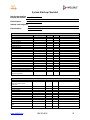
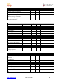
some of checks that must be performed prior to leaving the system. A System Start Up
Checklist is located near the end of this manual and should be followed for completion.
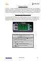
Navigation Using The Basic Display
The ArcticFox WiFi OEM board has multiple methods of user input. Evaporators ship
with the Basic Display installed on the right evaporator end panel. This display uses
KE2 Therm’s familiar menu structure to allow service technicians to change the major
setpoints. The setpoints may also be accessed using the controller’s webpages.

www.welbilt.com 800-225-9916 20
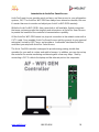
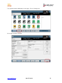
Introduction to ArcticFox Smart Access
ArcticFox Smart Access provides quick and easy, real time access to your refrigeration
systems, 24/7. The ArcticFox WiFi OEM has always been internet accessible, but now
it’s easier than ever to monitor and adjust your ArcticFox WiFi OEM remotely.
While the ArcticFox WiFi OEM’s free connectivity is still available, Kolpak recognizes
that some customers prefer the simplicity and convenience of ArcticFox Smart Access
to provide the benefits of the controller’s communication capability.
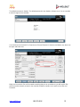
All the ArcticFox WiFi OEM needs is a physical connection to the network router with a
CAT-5 cable. Once enabled, ArcticFox Smart Access quickly connects to your personal
web portal, hosted by KE2 Therm, and provides a “customized” dashboard of all the
controllers you setup with ArcticFox Smart Access.
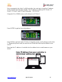
The Arctic Fox Wifi controller is designed to provide energy saving, trouble free
operation for your walk-in coolers and walk-in freezers. In addition, you can also set up
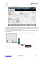
the controller for remote monitoring and alarming with a few easy steps. Start by
connecting a CAT-5 cable to the laptop and the ethernet port on the evaporator.
La page est en cours de chargement...
La page est en cours de chargement...
La page est en cours de chargement...
La page est en cours de chargement...
La page est en cours de chargement...
La page est en cours de chargement...
La page est en cours de chargement...
La page est en cours de chargement...
La page est en cours de chargement...
La page est en cours de chargement...
La page est en cours de chargement...
La page est en cours de chargement...
La page est en cours de chargement...
La page est en cours de chargement...
La page est en cours de chargement...
La page est en cours de chargement...
-
 1
1
-
 2
2
-
 3
3
-
 4
4
-
 5
5
-
 6
6
-
 7
7
-
 8
8
-
 9
9
-
 10
10
-
 11
11
-
 12
12
-
 13
13
-
 14
14
-
 15
15
-
 16
16
-
 17
17
-
 18
18
-
 19
19
-
 20
20
-
 21
21
-
 22
22
-
 23
23
-
 24
24
-
 25
25
-
 26
26
-
 27
27
-
 28
28
-
 29
29
-
 30
30
-
 31
31
-
 32
32
-
 33
33
-
 34
34
-
 35
35
-
 36
36


Kolpak Tru-Dmnd by ArcticFox MAC7/8 Manuel utilisateur
- Taper
- Manuel utilisateur
- Ce manuel convient également à
dans d''autres langues
Documents connexes

Autres documents
-
NAPOLEON NT13A018C-1 Manuel utilisateur
-
Maytag C7B(A,H)M0 Guide d'installation
-
-
Medallion C6BH-X Guide d'installation
-
Hoshizaki HR15A-G Manuel utilisateur
-
Hoshizaki RM-7-HC Manuel utilisateur
-
-
Manitowoc RF0399 Le manuel du propriétaire
-
Manitowoc RF-0244 Mode d'emploi
-