NAPOLEON WTACS0042RA1-N Manuel utilisateur
- Catégorie
- Climatiseurs split-system
- Taper
- Manuel utilisateur

IOM
W415-3148 / A / 10.04.23
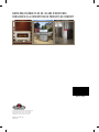
SEER2 13.4 & SEER2 14.3 CENTRAL AIR CONDITIONERS
Wolf Steel Ltd., 24 Napoleon Rd., Barrie, ON, L4M 0G8 Canada /
103 Miller Drive, Crittenden, Kentucky, USA, 41030
• www.napoleon.com •
MANUFACTURER RESERVES THE RIGHT TO DISCONTINUE, OR CHANGE AT ANY TIME,
SPECIFICATIONS OR DESIGNS WITHOUT NOTICE AND WITHOUT INCURRING OBLIGATIONS.
INSTALLATION AND OPERATING
INSTRUCTIONS
Certified to CSA C22.2 No. 60335-2-40:17
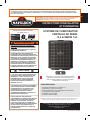
• SEER2 13.4 & SEER2 14.3 eciencies
• Capacities from 1.5 ton to 5.0 tons
• Utilizes environmentally friendly R-410A refrigerant
• High Eciency Compressors
• Micro Channel Condenser
• Swept Fan Blades
Congratulations on the purchase of your Napoleon Air Conditioner.
Napoleon’s line of Split Air Conditioners oer industry leading quality
and are equipped with multiple advanced features:
FEATURES:
INSTALLER: PLEASE FAMILIARIZE YOURSELF WITH THIS MANUAL BEFORE
PROCEEDING WITH THE INSTALLATION. LEAVE THIS MANUAL
WITH THE APPLIANCE FOR FUTURE REFERENCE.
CONSUMER: RETAIN THIS MANUAL FOR FUTURE REFERENCE.
INSPECT THE SHIPPING CONTAINER IMMEDIATELY UPON RECEIVING YOUR UNIT. ANY DAMAGE SHOULD BE NOTED ON
FREIGHT BILL BEFORE SIGNING AND CLAIMS SHOULD BE FILLED WITH CARRIER AS SOON AS POSSIBLE. MAKE SURE
THAT RATING PLATE MATCHES THE MODEL NUMBER YOU PURCHASED.
ELECTRICAL SHOCK, FIRE OR EXPLOSION
HAZARD. FAILURE TO FOLLOW SAFETY
WARNINGS AND INSTRUCTIONS EXACTLY
COULD RESULT IN SERIOUS INJURY, DEATH
OR PROPERTY DAMAGE.
THIS INFORMATION IS INTENDED FOR USE
BY QUALIFIED HVAC TECHNICIANS
POSSESSING ADEQUATE BACKGROUNDS OF
ELECTRICAL AND MECHANICAL
EXPERIENCE. ANY ATTEMPT TO REPAIR A
CENTRAL AIR CONDITIONING PRODUCT
MAY RESULT IN PERSONAL INJURY AND/OR
PROPERTY DAMAGE. THE MANUFACTURER
OR SELLER CANNOT BE RESPONSIBLE
FOR THE INTERPRETATION OF THIS
INFORMATION, NOR CAN IT ASSUME ANY
LIABILITY IN CONNECTION WITH ITS USE.
UNIT CONTAINS R-410A REFRIGERANT
AND POE COMPRESSOR OIL! USE ONLY
R-410A REFRIGERANT AND APPROVED POE
COMPRESSOR OIL. REFRIGERANT LINES
MUST BE BRAZED AND RATED FOR
R-410A PRESSURES!
PROPER SERVICE EQUIPMENT IS REQUIRED.
USE ONLY R-410A APPROVED SERVICE
EQUIPMENT. FAILURE TO USE PROPER
SERVICE TOOLS MAY RESULT IN EQUIPMENT
DAMAGE OR PERSONAL INJURY.
INSTALLATION SHALL BE MADE IN
ACCORDANCE WITH THE REQUIREMENTS
OF THE LOCAL UTILITY AND OTHER
AUTHORITIES HAVING JURISDICTION,
THE NATIONAL ELECTRICAL CODE IN THE
UNITED STATES AND THE CANADIAN
ELECTRICAL CODE CSA C22.1 PART 1
(LATEST EDITION) IN CANADA. ANY
ALTERATION OF INTERNAL WIRING WILL
VOID CERTIFICATION AND WARRANTIES.
WARNING !
!
CAUTION
! !

2
IOM
IOM
W415-3148 / A / 10.04.23
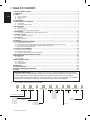
TABLE OF CONTENTS
1. MODEL NOMENCLATURE ..... .................................................................................................................................2
2. OVERVIEW ............................... .................................................................................................................................3
3. SAFETY ..................................... .................................................................................................................................3
3.1 SAFETY SYMBOLS ............................................................................................................................................................. 3
3.2 SAFETY RULES ............................................................................................................................................................................. 4
3.3 CODES ............................................................................................................................................................................................. 5
4. LIMITATIONS ............................ .................................................................................................................................5
5. LOCATION AND CLEARANCE ......................................................................................................................6
5.1 CLEARANCE ............................................................................................................................................................................. 6
5.2 LOCATION RESTRICTIONS ............................................................................................................................................................. 6
6. INSTALLATION ........................ .................................................................................................................................7
6.1 SUPPORT ............................................................................................................................................................................. 7
6.2 UNIT PLACEMENT ............................................................................................................................................................. 7
6.3 REFRIGERANT LINE SET INSTALLATION ............................................................................................................................ 8
7. EVACUATION ........................... ...............................................................................................................................13
7.1 EVACUATE THE REFRIGERANT LINES AND INDOOR COIL .......................................................................................... 13
8. SERVICE VALVES ................... ...............................................................................................................................14
8.1 OPEN THE SERVICE VALVES ........................................................................................................................................... 14
9. ELECTRICAL .......................... ...............................................................................................................................15
9.1 HIGH VOLTAGE ........................................................................................................................................................................... 15
10. S TART U P ................................. ...............................................................................................................................19
11. SYSTEM CHARGE ADJUSTMENT ....................................................................................................................20
11.1 SYSTEM TOTAL CHARGE ........................................................................................................................................................... 20
11.2 ADJUSTING SYSTEM CHARGE FOR SYSTEMS USING THERMOSTATIC EXPANSION VALVES ......................... 20
11.3 ADJUSTING SYSTEM CHARGE FOR SYSTEMS USING FIXED ORIFICE .......................................................................... 21
11.4 RECORD SYSTEM INFORMATION ........................................................................................................................................... 21
12. CHECKOUT PROCEDURES .. ...............................................................................................................................22
12.1 INSTRUCTING THE OWNER ........................................................................................................................................... 22
12.2 CHECKOUT PROCEDURE ........................................................................................................................................................... 22
12.3 SYSTEM OPERATION CHECKOUT PROCEDURE .......................................................................................................... 22
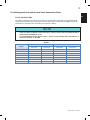
13. AIR CONDITIONING TROUBLESHOOTING .......................................................................................................23
14. MAINTENANCE ....................... ...............................................................................................................................25
14.1 INDOOR ........................................................................................................................................................................................... 25
14.2 OUTDOOR ........................................................................................................................................................................... 25
15. REPLACEMENT PARTS ........ ...............................................................................................................................26
15.1 PARTS LIST ........................................................................................................................................................................... 26
15.2 EXPLODED VIEW ........................................................................................................................................................................... 28
15.3 ACCESSORIES ........................................................................................................................................................................... 29
16. WARRANTY .............................. ...............................................................................................................................30
17. SERVICE HISTORY ................. ...............................................................................................................................31
18. OWNER’S SERVICE INFORMATION .......................................................................................................32
19. NOTES ...................................... ...............................................................................................................................33
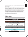
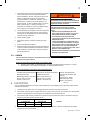
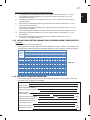
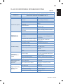
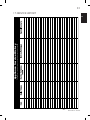
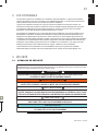
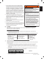
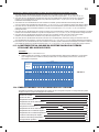
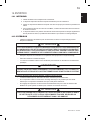
1. MODEL NOMENCLATURE
SHIPPING INSPECTION: The unit is shipped in one package, completely assembled and wired. Inspect
the shipping container immediately upon receiving your unit. If it appears that damage has occurred, it should
be noted on the freight bill before signing. Damage claims should be led with the carrier as quickly as
possible. Check the rating plate (at the front of the access panel) to conrm cooling capacities. The unit MUST
be operated only with the type of refrigerant, oil and electrical supply noted on the rating plate.
C
Type
A
SEER2 Rating
R
Compressor Type
T
Configuration
T=Top Discharge / S=Side Discharge
W
Wolf
A = 13.0-13.9
B = 14.0-14.9
C = 15.0-15.9
D = 16.0-16.9
E = 17.0-17.9
F = 18.0-18.9
G = 19.0-19.9
H = 20.0-20.9
C = Air Conditioner
H = Heat Pump
00 None
18 = 1.5 Tons
24 = 2.0 Tons
30 = 2.5 Tons
36 = 3.0 Tons
42 = 3.5 Tons
48 = 4.0 Tons
60 = 5.0 Tons
00
1st Capacity
R = Rotary Fixed
S = Scroll Fixed
V = Rotary Variable
18
2nd Capacity
R
Ref. Gas
A
Major Revision
A
B
C
1
Minor Revision
1
2
3
N
Brand
N = Napoleon
C = Continental
R = R410A
-

3
IOM
W415-3148 / A / 10.04.23
These instructions cover installation of Napoleon Split System Air Conditioners. Napoleon’s line of Split Air
Conditioners oer industry leading quality and reliability. All outdoor units have been factory run-tested and
ready for easy installation.
Napoleon’s line of Split Air Conditioners are designed to perform for many years. These instructions are
intended as an aid to the licensed service technician to properly install the unit. Improper installation may
damage equipment, void the warranty, and can create a hazard, resulting in property damage, injury or death.
Our air conditioning systems and components are designed to be installed by qualied HVAC technicians
ONLY. The installation of air conditioning systems includes electrical and refrigerant connections and is
regulated by a multiple sets of laws, codes and guidelines, at the federal, state and local levels. It is the
installer’s responsibility to install the product in accordance with all applicable codes and regulations. It is the
homeowner’s responsibility to properly maintain the equipment. NO WARRANTY is oered for the products
that were installed by unlicensed/unauthorized persons. Failure to comply with this policy could lead to
violations of applicable laws that are punishable.
Documentation and specications are continuously updated and subject to change. Please download the latest
version of specications and manuals at http://www.napoleon.com.
2. OVERVIEW
3. SAFETY
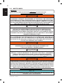
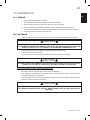
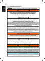
3.1 SAFETY SYMBOLS
Understand and pay particular attention to the words DANGER, WARNING, and CAUTION and the following
de ned symbols are used throughout this manual to notify the reader of potential hazards of varying risk levels.
HIGHLIGHTS SUGGESTIONS WHICH WILL RESULT IN ENHANCED INSTALLATION,
RELIABILITY, OR OPERATION.
NOTE
INDICATES A POTENTIALLY HAZARDOUS SITUATION WHICH, IF NOT AVOIDED,
COULD RESULT IN DEATH OR SERIOUS INJURY.
WARNING
!
!
SUGGESTS IMPORTANT PROCEDURE STEPS TO INSURE PROPER INSTALLATION,
RELIABILITY, OR OPERATION.
IMPORTANT
! !
INDICATES AN IMMINENTLY HAZARDOUS SITUATION WHICH, IF NOT AVOIDED, WILL
RESULT IN DEATH OR SERIOUS INJURY.
DANGER
! !
INDICATES A POTENTIAL HAZARDOUS SITUATION WHICH, IF NOT AVOIDED, MAY
RESULT IN MINOR OR MODERATE INJURY. IT MAY ALSO BE USED TO ALERT
AGAINST UNSAFE PRACTICES.
CAUTION
! !
H3.3.2. Safety Symbols
C
Type
A
SEER2 Rating
R
Compressor Type
T
Configuration
T=Top Discharge / S=Side Discharge
W
Wolf
A = 13.0-13.9
B = 14.0-14.9
C = 15.0-15.9
D = 16.0-16.9
E = 17.0-17.9
F = 18.0-18.9
G = 19.0-19.9
H = 20.0-20.9
C = Air Conditioner
H = Heat Pump
00 None
18 = 1.5 Tons
24 = 2.0 Tons
30 = 2.5 Tons
36 = 3.0 Tons
42 = 3.5 Tons
48 = 4.0 Tons
60 = 5.0 Tons
00
1st Capacity
R = Rotary Fixed
S = Scroll Fixed
V = Rotary Variable
18
2nd Capacity
R
Ref. Gas
A
Major Revision
A
B
C
1
Minor Revision
1
2
3
N
Brand
N = Napoleon
C = Continental
R = R410A
-

4
IOM
IOM
W415-3148 / A / 10.04.23
THIS INFORMATION IS INTENDED FOR USE BY QUALIFIED HVAC TECHNICIANS
POSSESSING ADEQUATE BACKGROUNDS OF ELECTRICAL AND MECHANICAL
EXPERIENCE. ANY ATTEMPT TO REPAIR A CENTRAL AIR CONDITIONING PRODUCT MAY
RESULT IN PERSONAL INJURY AND/OR PROPERTY DAMAGE. THE MANUFACTURER OR
SELLER CANNOT BE RESPONSIBLE FOR THE INTERPRETATION OF THIS INFORMATION,
NOR CAN IT ASSUME ANY LIABILITY IN CONNECTION WITH ITS USE.
UNIT CONTAINS R-410A REFRIGERANT AND POE COMPRESSOR OIL.
USE ONLY R-410A REFRIGERANT AND APPROVED POE COMPRESSOR OIL.
REFRIGERANT LINES MUST BE BRAZED AND RATED FOR R410 PRESSURES!
PROPER SERVICE EQUIPMENT IS REQUIRED. USE ONLY R-410A APPROVED SERVICE
EQUIPMENT. FAILURE TO USE PROPER SERVICE TOOLS MAY RESULT IN EQUIPMENT
DAMAGE OR PERSONAL INJURY.
DURING INSTALLATION, TESTING, SERVICING, AND TROUBLESHOOTING OF THIS
PRODUCT, IT MAY BE NECESSARY TO WORK WITH ELECTRICAL COMPONENTS.
THERE IS A RISK OF ELECTRIC SHOCK. IT CAN CAUSE INJURY OR DEATH:
DISCONNECT ALL REMOTE ELECTRIC POWER SUPPLIES BEFORE SERVICING!
HOT SURFACE! DO NOT TOUCH TOP OF COMPRESSOR.
COMPRESSOR AND DISCHARGE PIPES MAY BE EXTREMELY HOT.
IT MAY CAUSE MINOR TO SEVERE BURNING.
ALL R-410A SYSTEMS USE POE OIL. POE OIL EASILY ABSORBS MOISTURE FROM THE
AIR. A SYSTEM WHICH HAS BEEN EXPOSED TO THE ATMOSPHERE FOR MORE THAN
4 HOURS REQUIRES THAT THE COMPRESSOR OIL BE REPLACED. NEVER BREAK A
VACUUM WITH AIR AND ALWAYS CHANGE THE FILTER DRIER WHEN OPENING THE
SYSTEM FOR COMPONENT REPLACEMENT.
WARNING
! !
WARNING
! !
CAUTION !
!
CAUTION !
!
H3.3_AC
H3.4.3_AC
THESE INSTRUCTIONS ARE INTENDED AS AN AID TO QUALIFIED SERVICE PERSONNEL
FOR PROPER INSTALLATION, ADJUSTMENT AND OPERATION OF THIS UNIT. READ THESE
INSTRUCTIONS THOROUGHLY BEFORE ATTEMPTING INSTALLATION OR OPERATION.
FAILURE TO FOLLOW THESE INSTRUCTIONS MAY RESULT IN IMPROPER INSTALLATION,
ADJUSTMENT, SERVICE OR MAINTENANCE, POSSIBLY RESULTING IN FIRE, ELECTRICAL
SHOCK, EXPLOSION, PROPERTY DAMAGE, PERSONAL INJURY OR DEATH.
WARNING
! !
3.2 SAFETY RULES
H6.0
IMPORTANT:
READ THE FOLLOWING INSTRUCTIONS COMPLETELY BEFORE INSTALLING!
USE ONLY AUTHORIZED HVAC PARTS. USE OF OTHER PARTS MAY VOID WARRANTY OR
ADVERSELY IMPACT PERFORMANCES.
NOTE

5
IOM
W415-3148 / A / 10.04.23
3.3 CODES
H6.3_AC
This unit must be installed in accordance with all local codes, by-laws and regulations by those
authorities having jurisdiction.
Electrical connections must be made in accordance with:
a. Canada: current edition of CAN/CSA C22.1 and C22.2, Canadian Electrical Code (Part 1 and 2).
b. United States: current edition of ANSI/NFPA 70, National Electrical Code.
Codes and additional information may be obtained from:
Canadian Standards Association
5060 Spectrum Way
Mississauga, Ontario, L4W 5N6
Phone: (416) 747-4000
website: www.csa.ca
National Fire Protection Association
1 Batterymarch Park
Quincy, MA, 02169-7471
Phone: (617) 770-3000
website: www.nfpa.org
American Gas Association
400 North Capitol Street, NW,
Suite 450
Washington DC, 20001
Phone: (202) 824-7000
website: www.aga.org
1. Only trained service technicians familiar with standard
service instructions and training materials should
attempt installation, service, and repair of these units.
Failure to follow these instructions may result in
improper installation, adjustment, alteration, service,
maintenance, or use that can cause explosion, re,
electrical shock, or other conditions which may cause
death, personal injury, or property damage. For
information or assistance, consult a qualied installer,
service agency, your distributor or branch.
2. Unit contains R-410A refrigerant and POE compressor
oil! Use only R-410A refrigerant and approved POE
compressor oil. Refrigerant lines must be brazed and
rated for R-410A pressures!
3. Follow all safety codes.
4. Wear safety glasses, protective clothing, and work
gloves.
5. Have re extinguisher available.
6. Read instructions thoroughly and follow all warnings or
cautions included in literature and attached to the unit.
Consult federal, provincial, state, and local codes for
special requirements.
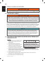
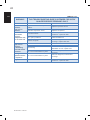
The unit should be installed in accordance with all National, Provincial/State and Local Safety Codes and the
limitations listed below:
1. Limitations for the indoor unit, coil, and appropriate accessories must also be observed.
2. The outdoor unit must not be installed with any duct work in the air stream. The outdoor fan is the propeller
type and is not designed to operate against any additional external static pressure.
3. The maximum and minimum conditions for operation must be observed to assure a system that will give
maximum performance with minimum service.
4. The unit should not be operated at outdoor temperatures below 50° F without an approved low ambient
operation accessory kit installed.
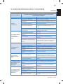
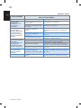
Ambient Air Temperature
on Outdoor Coil
Air Temperature
on Indoor Coil
Min. DB
Max. DB
Min. WB
Max. WB
50 °F (10 °C)
115 ° F (46 °C)
57 °F (14 °C)
72 °F (22 °C)
TABLE 1.
H3.95
REFRIGERANT UNDER PRESSURE!
ALWAYS PRACTICE SAFE HANDLING OF
REFRIGERANTS. FAILURE TO FOLLOW PROPER
PROCEDURES MAY CAUSE PROPERTY DAMAGE,
PERSONAL INJURY OR DEATH.
REFRIGERANTS ARE HEAVIER THAN AIR AND
CAN CAUSE SUFFOCATION. TO AVOID
POSSIBLE DIFFICULTY IN BREATHING OR
DEATH:
• NEVER PURGE REFRIGERANT INTO AN
ENCLOSED ROOM OR SPACE. BY LAW, ALL
REFRIGERANTS MUST BE RECLAIMED.
• IF AN INDOOR LEAK IS SUSPECTED,
THOROUGHLY VENTILATE THE AREA BEFORE
BEGINNING WORK.
• LIQUID REFRIGERANT CAN BE VERY COLD.
TO AVOID POSSIBLE FROSTBITE OR BLIND-
NESS, AVOID CONTACT AND WEAR GLOVES
AND GOGGLES. IF LIQUID REFRIGERANT
DOES CONTACT YOUR SKIN OR EYES, SEEK
MEDICAL HELP IMMEDIATELY.
•
NEVER BURN REFRIGERANT, AS POISONOUS
GAS WILL BE PRODUCED.
WARNING
! !
4. LIMITATIONS

6
IOM
IOM
W415-3148 / A / 10.04.23
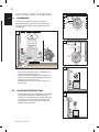
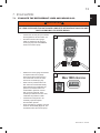
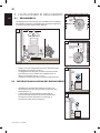
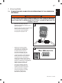
The minimum clearances required for installation
and accessibility are shown below. These clearances
should be followed unless otherwise approved by the
manufacturer.
• Ensure the top discharge area is unrestricted for at
least 60” above the unit (Figure 1.).
• Clearance must be provided in front of the access
panel for servicing and adequate airow around the
cabinet as shown on Fig.1, 2 & 3.
• The distance in between two or more units will be
24” minimum.
12”
12”
12”
12”
12”
12”
Service
Access
Panel Service
Access
Panel
Min
MIN. 24” clearance
for service
from one side
wall
wall
shrubs
shrubs
wall
24”
12”
12”
12”
12”
12”
12”
Service
Access
Panel Service
Access
Panel
Min
MIN. 24” clearance
for service
from one side
wall
wall
shrubs
shrubs
wall
24”
• Do not locate unit close to bedrooms or areas where
operational sounds may be objectionable (Fig. 4).
• Outdoor unit location must be far enough away from
any structure to prevent excess runo water from
pouring directly on to the unit (Fig. 5). Check with
National and Local Codes.
2
3
5
4
12”
60”
12”
Unrestricted
Shrubs
Wall
24”
Unrestricted
ACCESS
PANEL
ACCESS
PANEL
1
5. LOCATION AND CLEARANCE
5.1 CLEARANCE
5.2 LOCATION RESTRICTIONS

7
IOM
W415-3148 / A / 10.04.23
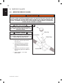
6. INSTALLATION
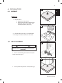
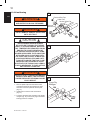
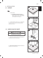
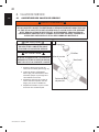
6.1 SUPPORT
6.2 UNIT PLACEMENT
Support pad:
1. The pad must be:
a. separate from any structure.
b. properly sized according to the size of the
cabinet. No portion of the cabinet shall
overhang beyond the pad (Fig. 6).
2. The pad must be level (Fig. 7). The pad location
must comply with National, State, and Local codes.
3. Remove screws holding four brackets to the pallet
and lift o the clips (Fig. 8).
4. Center, position and place the unit onto pad (Fig. 9).
BEFORE INSTALLATION, REMOVE THE SHIPPING
BRACKETS.
IMPORTANT !
!
Grade
2” min
6
LEVEL
7
8
9

8
IOM
IOM
W415-3148 / A / 10.04.23
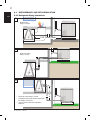
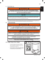
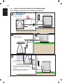
100’ (30m) max
10
• Maximum line
length = 100 feet.
6.3 REFRIGERANT LINE SET INSTALLATION
6.3.1 Refrigerant Piping Limitations
60’ (18m) max
11
60’ (18m) max
12
• Maximum vertical
height = 60 feet.
• Maximum vertical height = 60 feet.
• Compressor crankcase heater is required for
line lengths over 60 feet.
• Use only the line diameters indicated in
TABLE 2.

9
IOM
W415-3148 / A / 10.04.23
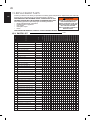
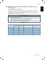
6.3.2 Refrigerant Line and Service Valve Connection Sizes
MODEL
Line Sizes Service Valve Connection Sizes
Vapor Line Liquid Line
Vapor Line
Connection
Liquid Line
Connection
1.5 Tons 3/4 3/8 3/4 3/8
2.0 Tons 3/4 3/8 3/4 3/8
2.5 Tons 3/4 3/8 3/4 3/8
3.0 Tons
3/4
3/8
3/4
3/8
3.5 Tons 7/8 3/8 7/8 3/8
4.0 Ton s 7/8 3/8 7/8 3/8
5.0 Ton s 7/8 3/8 7/8 3/8
PIPING CONNECTIONS
The outdoor condensing unit must be connected to the matched indoor evaporator coil using eld supplied
refrigerant grade (ACR) copper tubing that is internally clean and dry. Units should be installed only with the
tubing sizes for approved system combinations as specied in Table 2.
• USING A LARGER THAN SPECIFIED LINE SIZE COULD RESULT IN OIL RETURN PROBLEMS.
• USING TOO SMALL A LINE WILL RESULT IN LOSS OF CAPACITY AND OTHER PROBLEMS CAUSED BY
INSUFFICIENT REFRIGERANT FLOW.
• SLOPE HORIZONTAL VAPOR LINES AT LEAST 1” EVERY 20 FEET TOWARD THE OUTDOOR UNIT TO
FACILITATE PROPER OIL RETURN.
NOTE
TABLE 2.

10
IOM
IOM
W415-3148 / A / 10.04.23
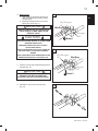
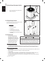
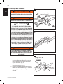
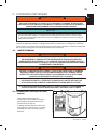
6.3.3 Line Brazing
1. Remove plastic caps from the service valve
connections. Remove the pressure port caps
and valve cores from pressure service ports
(Fig. 13).
Pressure
Service Port
Valve Core
Pressure Port Cap
Service Valve Cap
13
Insert Lines
14
Purge Dry
Nitrogen
IN
OUT
Dry
Nitrogen
15
2. Install lines into service valve connections
(Fig. 14).
3. Purge the refrigerant line and indoor coil with dry
nitrogen (Fig. 15). Continue to purge until whole
brazing process is complete.
WARNING
!!
WARNING
!!
DO NOT REMOVE SERVICE VALVE CAPS
UNTIL SECTION 7.
WARNING
!!
NEVER ATTEMPT TO REPAIR ANY BRAZED
CONNECTIONS WHILE THE SYSTEM IS
UNDER PRESSURE. PERSONAL INJURY
COULD RESULT.
CAUTION
! !
DRY NITROGEN SHOULD ALWAYS
BE SUPPLIED THROUGH THE TUBING
WHILE IT IS BEING BRAZED, BECAUSE
THE TEMPERATURE REQUIRED IS HIGH
ENOUGH TO CAUSE OXIDATION OF
THE COPPER UNLESS AN INERT ATMO-
SPHERE IS PROVIDED. THE FLOW OF DRY
NITROGEN SHOULD CONTINUE UNTIL
THE JOINT HAS COOLED. ALWAYS USE
A PRESSURE REGULATOR AND SAFE-
TY VALVE TO INSURE THAT ONLY LOW
PRESSURE DRY NITROGEN IS INTRO-
DUCED INTO THE TUBING. ONLY A SMALL
FLOW IS NECESSARY TO DISPLACE AIR
AND PREVENT OXIDATION.
REFRIGERANT LINES MUST BE BRAZED
AND RATED FOR R-410A PRESSURE!

11
IOM
W415-3148 / A / 10.04.23
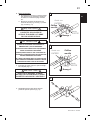
Dry Nitrogen
IN
Nitrogen
OUT
Wet Rag
Braze 2
2
17
Braze 1
1
Dry Nitrogen
IN
Nitrogen
OUT
Wet Rag
16
18
4. Brazing steps:
a. Wrap a wet rag around the valve body to
avoid heat damage and continue the dry
nitrogen purge.
b. Braze the refrigerant lines to the service
valves (Fig. 16 and Fig. 17).
5. Continue to purge until whole brazing process is
complete (Fig. 17).
WHEN BRAZING LINE SET TO SERVICE
VALVES POINT FLAME AWAY FROM
SERVICE VALVE.
IMPORTANT
! !
ONCE THE BRAZING IS COMPLETE,
REMOVE THE WET RAG BEFORE
STOPPING THE DRY NITROGEN PURGE.
IMPORTANT
! !
6. Reinstall the valve cores to service ports
(Fig. 18).
CAUTION
! !
AVOID BREATHING VAPORS OR FUMES FROM
BRAZING OPERATIONS.
PERFORM OPERATIONS ONLY IN WELL−
VENTILATED AREAS.
WEAR GLOVES AND PROTECTIVE GOGGLES
OR FACE SHIELD TO PROTECT AGAINST
BURNS.
WASH HANDS WITH SOAP AND WATER AFTER
HANDLING BRAZING ALLOYS AND FLUX.

12
IOM
IOM
W415-3148 / A / 10.04.23
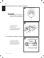
• The Vapor Line must always
be insulated (Fig. 21).
• DO NOT allow the liquid line and
vapor line to come in direct (metal
to metal) contact to each other.
Test for leak
• Pressurize the refrigerant lines and
evaporator coil to 350-400 PSIG using dry
nitrogen (Fig. 19). The nitrogen pressure
must be maintained for few minutes.
• If pressure decay is observed,
it is an indication of leak(s).
• Check for leaks by using a soap
solution at each brazed joint (Fig. 20).
19
20
21
6.3.4 Refrigerant Line Leak Test
6.3.5 Refrigerant Line Insulation

13
IOM
W415-3148 / A / 10.04.23
7. EVACUATION
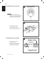
7.1 EVACUATE THE REFRIGERANT LINES AND INDOOR COIL
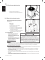
• Connect the vacuum pump to evacuate
the refrigerant line set and indoor coil.
• Evacuate until the micron gauge
reads no higher than 350 microns
or less (Fig. 22), then close OFF the
valve to the vacuum pump.
• Observe the micron gauge. Evacuation
is complete if the micron gauge
does not rise above 500 microns in
one minute and no more the 1000
microns in 10 minutes (Fig. 23).
• When vacuum pressure rises more
then 1000 microns but holds steady
below 2000 microns it indicates the
presence of moisture and/or non-
condensible or presence of small
leak. If vacuum pressure stays
constantly at 2000 microns or it rises,
it indicates the presence of leak.
• If the leak is found, perform the
necessary repair and repeat
the evacuation process.
• Once evacuation is complete, close the
valves on the manifold gauge set, turn
o and disconnect the vacuum pump.
WARNING
!!
DO NOT OPEN THE SERVICE VALVES UNTIL THE REFRIGERANT LINES AND INDOOR
COIL LEAK CHECK AND EVACUATION ARE COMPLETE. REFRIGERANT CAN LEAK AND
MAY CAUSING MILD TO SEVERE BURNS.
SCALE
OFF
350
ON
MICRONS
DIGITAL MICRON GAUGE
22
10 min
Max 1000 microns
23
SCALE
OFF
350
ON
MICRONS
DIGITAL MICRON GAUGE

14
IOM
IOM
W415-3148 / A / 10.04.23
8. SERVICE VALVES
8.1 OPEN THE SERVICE VALVES
EXTREME CAUTION MUST BE EXERCISED WHEN OPENING THE LIQUID LINE SERVICE
VALVE. TURN COUNTERCLOCKWISE UNTIL THE VALVE STEM JUST TOUCHES THE
ROLLED EDGE. NO TORQUE IS REQUIRED. FAILURE TO FOLLOW THIS WARNING WILL
RESULT IN ABRUPT RELEASE OF SYSTEM CHARGE AND MAY RESULT IN PERSONAL
INJURY AND/OR PROPERTY DAMAGE.
WARNING !
!
LEAK CHECK AND EVACUATION MUST
BE COMPLETED BEFORE OPENING THE
SERVICE VALVES.
IMPORTANT !
!
1. Remove the cap from vapor service
valve (Fig. 24)
2. Fully insert Allen key into the stem
and rotate counterclockwise until
valve stem just touches the rolled
edge.
3. Replace the valve stem cap. Tighten
the cap nger tight with an additional
1/6 turn.
4. Repeat STEPS 1 - 3 for Liquid
Service Valve.
Allen Key
Rolled Edge
Service Port
Service Valve
Cap
24
CAUTION
! !
THE VAPOR LINE SERVICE VALVE MUST
BE OPENED FIRST BEFORE OPENING THE
LIQUID LINE SERVICE VALVE.

15
IOM
W415-3148 / A / 10.04.23
9.1.1 High Voltage Power Supply
• The high voltage power supply must agree
with the equipment nameplate located on the
service panel cover (Fig. 25).
• Power wiring must comply with national, state,
and local codes. The wiring diagram is located
on the back side of the electrical cover.
25
9. ELECTRICAL
9.1 HIGH VOLTAGE
DURING INSTALLATION, TESTING, SERVICING, AND TROUBLESHOOTING OF THIS
PRODUCT, IT MAY BE NECESSARY TO WORK WITH ELECTRICAL COMPONENTS. THERE
IS A RISK OF ELECTRIC SHOCK THAT CAN CAUSE INJURY OR DEATH:
DISCONNECT ALL REMOTE ELECTRIC POWER SUPPLIES BEFORE SERVICING.
WARNING !!
ONLY COPPER CONDUCTORS MUST BE USED FOR ALL FIELD WIRING AND BE IN
ACCORDANCE WITH LOCAL, NATIONAL, FIRE, SAFETY AND ELECTRICAL CODES.
THIS UNIT MUST BE GROUNDED WITH A SEPARATE GROUND WIRE IN ACCORDANCE
WITH THE CODES MENTIONED ABOVE.
WARNING !
!
Make sure that electrical supply meets the values specied on the unit nameplate and wiring label. Power
wiring, disconnect switches, control (low voltage) wiring and over current protection must be supplied by the
installer. Wire size must be sized per National and Local Electrical codes requirements.
For units with rotary type compressor, identified by the letter R in the model number (example: WTACR)
a hard start capacitor must be installed if the system employs a non-bleed type TXV. Refer to section
9.1.6 for wiring and section 15.3 for recommended kit part number.
H3.80
WARNING !
!
SHUT OFF ELECTRICAL POWER AT THE FUSE BOX OR SERVICE PANEL BEFORE
MAKING ANY ELECTRICAL CONNECTIONS. FAILURE TO DO SO CAN CAUSE ELECTRICAL
SHOCK RESULTING IN PERSONAL INJURY OR DEATH.
• THE AIR CONDITIONER CABINET MUST HAVE AN UNINTERRUPTED GROUND.
• A GROUND LUG IS PROVIDED IN THE ELECTRICAL JUNCTION BOX.
• DO NOT USE REFRIGERANT PIPING AS A GROUND.
FAILING TO GROUND THE AIR CONDITIONER PROPERLY CAN RESULT IN ELECTRIC
SHOCK RESULTING IN PERSONAL INJURY OR DEATH.
NOTE

16
IOM
IOM
W415-3148 / A / 10.04.23
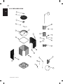
9.1.2 High Voltage Disconnect Switch
9.1.3 High Voltage Ground
• Install a separate disconnect switch at the
outdoor unit (Fig. 26).
Ground the outdoor unit per national, state, provincial
and local code requirements (Fig. 27).
Components:
1. Contactor
2. Dual Run Capacitor
3. Ground Lug
4. Thermostat Control Wire Feed
5. High Voltage Power Cable Feed
6. Compressor and High Pressure Switch
Wire Feed
26
1
2
54
6
3
27
9.1.4 Thermostat
• Room thermostat (purchased
separately) should be installed
approximately in the center of the
conditioned area on an INSIDE wall
and 5 feet (1.5m) above the oor.
• Do NOT install thermostat on an
outside wall or where it can be
exposed to sunlight or drafts.
Good thermostat locations are:
• in a living room or dining room,
• in a position where the thermostat will be in natural air circulation (not dead air space) but where the
thermostat will not be exposed to strong drafts from windows, doorways, or from a heating or cooling air
Bad Room Thermostat Locations:
• on an exterior building wall (exposed to outdoor temperature eects) where drafts from an exterior door will
aect its reading
• above or in the line of airow from a heating or cooling air supply register
• in direct sunlight
• in a kitchen, bath, or entry hallway or on a wall shared with a hot space such as a kitchen or boiler room
• in an alcove, behind an open door, behind furniture or next to concealed pipes or air ducts
• Do not place heat-emitting devices such as lamps or small appliances close to the thermostat. Their heat
may aect its operation.
CAUTION
ENSURE THE SYSTEM HAS A MINIMUM OF 5 MINUTES
OFF TIME BETWEEN STARTS. SYSTEM SHORT CYCLING
MIGHT LEAD TO SYSTEM FAILURE. REFER TO YOUR
THERMOSTAT MANUAL TO SET UP THE START-UP TIME
DELAY. IF UNAVAILABLE, AN ANTI-SHORT CYCLE KIT
(W370-0249) IS AVAILABLE (PURCHASED SEPARATELY).
!
!

17
IOM
W415-3148 / A / 10.04.23
28
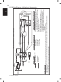
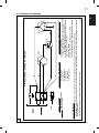
WIRING DIAGRAM / SCHÉMA DE CÂBLAGE
YY
BL
GND
GND LUG
COMP
BK
BK
R
R BR G/Y
LEGEND / LÉGENDE
HIGH VOLTAGE FIELD WIRING /
FIL HAUTE TENSION
COLOUR CODE / CODE DE COULEUR
BK - BLACK / NOIR
BL - BLUE / BLEU
BR - BROWN / BRUN
G - GREEN / VERT
R - RED / ROUGE
Y - YELLOW / JAUNE
COMPONENT NAME / NOM DES COMPOSANTS
C - CONTACTOR / CONTACTEUR
CAP - FAN AND COMPRESSOR DUAL RUN CAPACITOR / VENTILATEUR
ET LE COMPRESSEUR DOUBLE RUN CONDENSATEUR
CM - OUTDOOR FAN MOTOR / MOTEUR DE SOUFFLERIE EXTÉRIEUR
COMP - COMPRESSOR / COMPRESSEUR
GND - GROUND / TERRE
GND LUG - GROUND LUG / COSSE DE MISE À LA TERRE
HPS - HIGH PRESSURE SWITCH / COMMUTATEUR HAUTE PRESSION
NOTES / REMARQUES
1. WARNING: RISK OF ELECTRIC SHOCK. CAN CAUSE INJURY OR DEATH: DISCONNECT ALL REMOTE ELECTRIC POWER SUPPLIES BEFORE SERVICING.
AVERTISSEMENT. RISQUE DE CHOCS ÉLECTRIQUES. PEUT CAUSER DES BLESSURES ET MÊME ENTRAÎNER LA MORT. COUPER LES SOURCES D’ALIMENTATION À DISTANCE
AVANT LE DÉPANNAGE.
2. USE COPPER SUPPLY WIRES / UTILISER DES FILS D’ALIMENTATION EN CUIVRE. W385-0813/B
Y
R
CAP
CM
9.1.5 Wiring Diagram

18
IOM
IOM
W415-3148 / A / 10.04.23
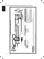
9.1.6 Wiring Diagram with Optional Accessories
AA
WIRING DIAGRAM / SCHÉMA DE CÂBLAGE
GND
GND LUG
COMP
BK
BK
R
R BR G/Y
LEGEND / LÉGENDE
HIGH VOLTAGE FIELD WIRING /
FIL HAUTE TENSION
COLOUR CODE / CODE DE COULEUR
BK - BLACK / NOIR
BL - BLUE / BLEU
BR - BROWN / BRUN
G - GREEN / VERT
R - RED / ROUGE
Y - YELLOW / JAUNE
COMPONENT NAME / NOM DES COMPOSANTS
C - CONTACTOR / CONTACTEUR
CAP - FAN AND COMPRESSOR DUAL RUN CAPACITOR / VENTILATEUR
ET LE COMPRESSEUR DOUBLE RUN CONDENSATEUR
CM - OUTDOOR FAN MOTOR / MOTEUR DE SOUFFLERIE EXTÉRIEUR
COMP - COMPRESSOR / COMPRESSEUR
GND - GROUND / TERRE
GND LUG - GROUND LUG / COSSE DE MISE À LA TERRE
HPS - HIGH PRESSURE SWITCH / COMMUTATEUR HAUTE PRESSION
NOTES / REMARQUES
1. WARNING: RISK OF ELECTRIC SHOCK. CAN CAUSE INJURY OR DEATH: DISCONNECT ALL REMOTE ELECTRIC POWER SUPPLIES BEFORE SERVICING
AVERTISSEMENT. RISQUE DE CHOCS ÉLECTRIQUES. PEUT CAUSER DES BLESSURES ET MÊME ENTRAÎNER LA MORT. COUPER LES SOURCES D’ALIMENTATION À DISTANCE
AVANT LE DÉPANNAGE.
2. USE COPPER SUPPLY WIRES / UTILISER DES FILS D’ALIMENTATION EN CUIVRE.
Y
R
CAP
CM
OPTIONAL WIRING /
FIL OPTIONNEL
SC - HARD START CAPACITOR KIT (OPTIONAL) / ENSEMBLE DU
CONDENSATEUR D’ALLUMAGE FORCÉ (OPTIONNEL)
BK 5 2
Y
R
1
SC
Y Y
BL
Y
BL
Y
BL
TIMER
[OPTIONAL]
TD
TD - TIME DELAY RELAY (OPTIONAL) / RELAIS DE TEMPORISATION
(OPTIONNEL)

19
IOM
W415-3148 / A / 10.04.23
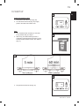
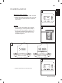
10. START UP
Perform the following steps:
1. Set System Thermostat to OFF (Fig. 29).
2. Turn disconnect switch ON (Fig. 30) to apply
power to the indoor and outdoor units.
Wait:
3. If no crankcase heater accessory is used, wait
ve (5) minutes and go to Step 5.
4. Wait one (1) hour before starting the unit, if
compressor crankcase heater accessory is used
and the Outdoor Ambient is below 70ºF. Refer to
(Fig. 31).
5. Set system thermostat to ON (Fig. 32).
HOLD
HEATOFFCOOL
FAN SYSTEM PROG/MAN
AUTOON
time:
thu:
18:30
day:
72F
32
31
30
HOLD
HEATOFFCOOL
FAN SYSTEM PROG/MAN
AUTOON
time:
thu:
18:30
day:
OFF
29

20
IOM
IOM
W415-3148 / A / 10.04.23
11. SYSTEM CHARGE ADJUSTMENT
REFRIGERANT CHARGING MUST ONLY BE ATTEMPTED BY QUALIFIED CONTRACTORS. IMPROP-
ER SYSTEM CHARGE CAN REDUCE SYSTEM CAPACITY AND MAY CAUSE EQUIPMENT DAMAGE.
WARNING !!
DO NOT LEAVE THE SYSTEM OPEN TO THE ATMOSPHERE. DO NOT ATTEMPT TO PUMP “TOTAL
SYSTEM CHARGE” INTO OUTDOOR UNIT FOR MAINTENANCE, SERVICE, ETC. THIS MAY CAUSE
DAMAGE TO THE COMPRESSOR AND/OR OTHER COMPONENTS. THE OUTDOOR UNIT ONLY HAS
ENOUGH VOLUME FOR THE “FACTORY CHARGE”, NOT FOR THE “TOTAL SYSTEM CHARGE”. IT IS
UNLAWFUL TO KNOWINGLY VENT, RELEASE OR DISCHARGE REFRIGERANT INTO THE OPEN AIR
DURING REPAIR, SERVICE, MAINTENANCE, OR THE FINAL DISPOSAL OF THIS UNIT.
WARNING !!
All air conditioning units come pre-charged with enough refrigerant (R-410A ) for an appropriately matched
indoor evaporator coil. For eld installed line set, a correction of 0.6 Oz of R-410A per foot of line set is
required for 3/4” suction line diameter and 0.7 Oz of R-410A per foot of line set is required for 7/8” suction line
diameter. Liquid line shall be 3/8” diameter. Using evaporator coils that have not been approved as a match by
the manufacturer is not recommended. Refer to AHRI directory for matched evaporator coil for your system.
The system charge shall be adjusted according to section 11.2 or 11.3 depending on the application.
To obtain an ecient system matching AHRI performance, units with either thermostatic expansion
valves or piston ow raters must be installed in the vertical direction with the liquid refrigerant owing
downwards or upwards, feeding the indoor evaporator coil. The capillary tubes and expansion valve
location can be adjusted to ensure that the ow through both of the slabs of the A-Coil have equal ow
of refrigerant. If the temperature dierence does not vary more than 10°F between the two slabs of
A-coil, it indicates the equal ow of refrigerant through the each of the slabs.
NOTE
11.1 SYSTEM TOTAL CHARGE
11.2 ADJUSTING SYSTEM CHARGE FOR SYSTEMS USING THERMOSTATIC
EXPANSION VALVES
Procedure:
1. Connect charging hose from liquid port on the
refrigerant bottle to charging service port on
manifold gauge.
2. Open refrigerant bottle and purge hose.
3. Connect low side of manifold gauge set to the
pressure port on vapor line service valve.
4. Connect the high side of the manifold gauge set
to pressure port on liquid line service valve.
5. Temporarily install a temperature measuring device on the liquid line near the liquid service valve and
one at the vapor line near the vapor service valve. Ensure that the temperature measuring device makes
adequate contact and insulated for accurate readings.
6. Operate the system for at least 10 minutes.
7. Check subcooling and superheat. Systems using thermostatic expansion valves should have a
subcooling of 7°F to 9°F and superheat of 7°F to 9°F.
8. Record Total Charge on the nameplate and manual.
H3.96
CAUTION
! !
TO PREVENT PERSONAL INJURY, CAREFULLY
CONNECT AND DISCONNECT MANIFOLD
GAUGE HOSES. ESCAPING LIQUID
REFRIGERANT CAN CAUSE BURNS. DO NOT
VENT REFRIGERANT INTO THE ATMOSPHERE.
RECOVER ALL REFRIGERANT DURING SYSTEM
REPAIR AND BEFORE FINAL UNIT DISPOSAL.
La page est en cours de chargement...
La page est en cours de chargement...
La page est en cours de chargement...
La page est en cours de chargement...
La page est en cours de chargement...
La page est en cours de chargement...
La page est en cours de chargement...
La page est en cours de chargement...
La page est en cours de chargement...
La page est en cours de chargement...
La page est en cours de chargement...
La page est en cours de chargement...
La page est en cours de chargement...
La page est en cours de chargement...
La page est en cours de chargement...
La page est en cours de chargement...
La page est en cours de chargement...
La page est en cours de chargement...
La page est en cours de chargement...
La page est en cours de chargement...
La page est en cours de chargement...
La page est en cours de chargement...
La page est en cours de chargement...
La page est en cours de chargement...
La page est en cours de chargement...
La page est en cours de chargement...
La page est en cours de chargement...
La page est en cours de chargement...
La page est en cours de chargement...
La page est en cours de chargement...
La page est en cours de chargement...
La page est en cours de chargement...
La page est en cours de chargement...
La page est en cours de chargement...
La page est en cours de chargement...
La page est en cours de chargement...
La page est en cours de chargement...
La page est en cours de chargement...
La page est en cours de chargement...
La page est en cours de chargement...
La page est en cours de chargement...
La page est en cours de chargement...
La page est en cours de chargement...
La page est en cours de chargement...
La page est en cours de chargement...
La page est en cours de chargement...
La page est en cours de chargement...
La page est en cours de chargement...
-
 1
1
-
 2
2
-
 3
3
-
 4
4
-
 5
5
-
 6
6
-
 7
7
-
 8
8
-
 9
9
-
 10
10
-
 11
11
-
 12
12
-
 13
13
-
 14
14
-
 15
15
-
 16
16
-
 17
17
-
 18
18
-
 19
19
-
 20
20
-
 21
21
-
 22
22
-
 23
23
-
 24
24
-
 25
25
-
 26
26
-
 27
27
-
 28
28
-
 29
29
-
 30
30
-
 31
31
-
 32
32
-
 33
33
-
 34
34
-
 35
35
-
 36
36
-
 37
37
-
 38
38
-
 39
39
-
 40
40
-
 41
41
-
 42
42
-
 43
43
-
 44
44
-
 45
45
-
 46
46
-
 47
47
-
 48
48
-
 49
49
-
 50
50
-
 51
51
-
 52
52
-
 53
53
-
 54
54
-
 55
55
-
 56
56
-
 57
57
-
 58
58
-
 59
59
-
 60
60
-
 61
61
-
 62
62
-
 63
63
-
 64
64
-
 65
65
-
 66
66
-
 67
67
-
 68
68


NAPOLEON WTACS0042RA1-N Manuel utilisateur
- Catégorie
- Climatiseurs split-system
- Taper
- Manuel utilisateur
dans d''autres langues
- English: NAPOLEON WTACS0042RA1-N User manual
Documents connexes
Autres documents
-
ClimateMaster Dedicated Outside Air Systems Le manuel du propriétaire
-
Maytag C7B(A,H)M0 Guide d'installation
-
Maytag C74B(A,H)MX Guide d'installation
-
-
Medallion C6BH-X Guide d'installation
-
GE AUH2436ZGDA Guide d'installation
-
-
 JB ELIMINATOR Vacuum Pump Manuel utilisateur
-
 Kolpak Tru-Dmnd by ArcticFox MAC7/8 Manuel utilisateur
-
Samsung MXD-A40K100E Guide d'installation

