ClimateMaster Dedicated Outside Air Systems Le manuel du propriétaire
- Taper
- Le manuel du propriétaire

Confi gured Packaged
Rooftop Solutions
2 SERIES & 4 SERIES
6-40 TONS
INSTALLATION, OPERATION
& MAINTENANCE MANUAL
97B0109N01
Revised: 19 Sept 2019
Rooftop SolutionsRooftop Solutions
Table of Contents
General Information . . . . . . . . . . . . . . . . . . . . . . . . . . . . . . . . . . 1
Code String . . . . . . . . . . . . . . . . . . . . . . . . . . . . . . . . . . . . . . . . . . 4
Pre-Installation . . . . . . . . . . . . . . . . . . . . . . . . . . . . . . . . . . . . . . 10
Dimensional Drawings. . . . . . . . . . . . . . . . . . . . . . . . . . . . . . . . 11
Unit Installation . . . . . . . . . . . . . . . . . . . . . . . . . . . . . . . . . . . . . 19
Service Clearance . . . . . . . . . . . . . . . . . . . . . . . . . . . . . . . . 19
Roof Curbs . . . . . . . . . . . . . . . . . . . . . . . . . . . . . . . . . . . . . .20
Rigging and Handling . . . . . . . . . . . . . . . . . . . . . . . . . . . . . 22
Unit and Component Weights . . . . . . . . . . . . . . . . . . . . . 23
Condensate Drain Piping . . . . . . . . . . . . . . . . . . . . . . . . . . 24
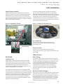
Air Cooled . . . . . . . . . . . . . . . . . . . . . . . . . . . . . . . . . . . . . . . 25
Water Source . . . . . . . . . . . . . . . . . . . . . . . . . . . . . . . . . . . . 25
Water Treatment . . . . . . . . . . . . . . . . . . . . . . . . . . . . . . . . 26
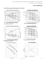
Glycol Performance Adjustment Factors Charts . . . . . . 27
Electrical . . . . . . . . . . . . . . . . . . . . . . . . . . . . . . . . . . . . . . . . . . .28
Pre-Startup . . . . . . . . . . . . . . . . . . . . . . . . . . . . . . . . . . . . . . . . . 29
Startup . . . . . . . . . . . . . . . . . . . . . . . . . . . . . . . . . . . . . . . . . . . .30
Superheat & Subcooling Flow Chart . . . . . . . . . . . . . . . . 32
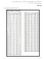
Refrigerant Temperature Pressure Chart . . . . . . . . . . . . 33
Temperature Sensor Chart . . . . . . . . . . . . . . . . . . . . . . . . 34
Startup and Warranty Registration Form . . . . . . . . . . . . 35
Refrigeration Circuit Diagram . . . . . . . . . . . . . . . . . . . . . . . . . 37
Refrigeration System. . . . . . . . . . . . . . . . . . . . . . . . . . . . . . . . .40
Refrigeration System Re-Processing . . . . . . . . . . . . . . . . . . . 42
Factory Installed Options . . . . . . . . . . . . . . . . . . . . . . . . . . . . .43
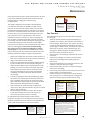
Maintenance . . . . . . . . . . . . . . . . . . . . . . . . . . . . . . . . . . . . . . . .47
Warranty . . . . . . . . . . . . . . . . . . . . . . . . . . . . . . . . . . . . . . . . . . .50

1
2 Series & 4 Series 6-40 Tons
Rev.: 19 Sept 2019
THE SMART SOLUTION FOR ENERGY EFFICIENCY
climatemaster.com
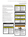
General Information
Unit Nameplate
Safety Information
Heat Pump applications. This manual provides general
information about the 2 Series and 4 Series units available in
6 – 40 tons.
attention notices appear. Read these items carefully
troubleshooting of the equipment. All labels
on unit access panels must be observed.
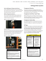
The unit nameplate is located on both the outside and the
inside of the main control panel door. It includes the unit
refrigerant charge.
DANGER: Immediate hazardous situation which, if not
avoided, will result in death or serious injury.
WARNING: Potentially hazardous situation which, if not
avoided, could result in death or serious injury.
CAUTION: Potentially hazardous situation or an unsafe
practice which, if not avoided, could result in minor or
moderate injury or product or property damage.
ATTENTION: Notifi cation of installed, operation or
maintenance information which is important, but not
hazard related.
ATTENTION
This furnace is not listed or suitable for drying or process
applications. Use in such applications voids any warranty and
manufacturer disclaims any responsibility for the furnace and/
or application.
ATTENTION
When pressure testing is at 1/2 psi or less, close the manual
shut off valve on the furnace before testing.
When pressure testing gas supply line at 1/2 psi or higher,
close manual gas valve and disconnect heater from supply line
to be tested. Cap or plug the supply line.
CAUTION/ATTENTION
CAUTION/ATTENTION
Gas-fi red furnaces are not
designed for use in hazardous
atmospheres containing
fl ammable vapors or
combustible dust, in
atmospheres containing
chlorinated or halogenated
hydrocarbons, or in
applications with airborne
substances containing
silicone.
Fours à gaz sont pas conçus
pour être utilisés dans des
atmosphères dangereuses
contenant des vapeurs
infl ammables ou poussières
combustibles, dans des
atmosphères contenant des
hydrocarbures chlorés ou
halogénés, ou dans des
applications avec des
substances dans l’air
contenant de la silicone.
CAUTION/ATTENTION
The presence of chlorine
vapors in the combustion air
supplied to gas-fi red heaters
presents a substantial
corrosion hazard.
La présence de vapeurs
de chlore dans l’air de
combustion fourni à ce four
a un haut risque de corrosion.
CAUTION/ATTENTION
Flue gases must be directed
away from combustion air
inlets to avoid recirculation
into combustion air supply.
Les gaz de combustion
doivent être dirigés loin de
prises d’air de combustion
pour éviter la recirculation
dans l’alimentation en air de
combustion.
CAUTION/ATTENTION
CAUTION/ATTENTION
All fi eld piping must be
pressure/leak tested prior
to operation. NEVER use an
open fl ame to check for leaks.
Use soap solution or other
leak detecting solution.
Gas pressure to appliance
controls must never exceed
13.5” w.c. (1/2 psi).
Toutes les conduites de gaz
reliés à l’appareil doivent être
inspectés pour des fuites
sous pression avant d’utiliser.
NE JAMAIS utiliser une
fl amme nue pour vérifi er les
fuites. Utilisez une solution
de savon ou autre solution de
détection des fuites.
Contrôles d’appareils à gaz
février. Pression ne doit
jamais dépasser 13.5” wc
(1/2 psi ).
ATTENTION
Internal water strainer requires cleaning.
WARNING/AVERTISSEMENT
WARNING/AVERTISSEMENT
WATER AND REFRIGERANT
SYSTEMS UNDER PRESSURE
• Isolate/Lockout source
and relieve pressure
BEFORE servicing
equipment.
• Failure to relieve pressure
may result in property
damage, serious bodily
injury or death!
EAU ET FRIGORIGÈNE
EQUIPEMENTS SOUS
PRESSION
• Isoler la source / de
verrouillage et de
soulager la pression
avant entretien de
l’équipement.
• Le défaut de soulager la
pression peut entraîner
des dommages matériels,
des blessures corporelles
graves ou la mort!

2
2 Series & 4 Series 6-40 Tons
Rev.: 19 Sept 2019
CLIMATEMASTER DOAS
ClimateMaster DOAS
General Information
To avoid possible injury or
death due to electrical shock,
open the power supply
disconnect switch and secure
it in an open position during
installation.
Pour éviter les blessures ou
la mort par électrocution,
ouvrir la interrupteur de
sécurité et fi xez-le en position
ouverte lors de l’installation.
WARNING/AVERTISSEMENT
Use all lifting points.
Improper lifting can cause
property damage, severe
personal injury, or death.
Utilisez tous les points de
levage. Le levage incorrect
peut entraîner des dommages
matériels, des blessures
graves ou la mort.
WARNING/AVERTISSEMENT
Only trained and qualifi ed
personnel should be allowed
to rig loads or operate load
rated cranes and/or hoist
assemblies. Do not use a
forklift to lift or maneuver the
unit. Failure to use load rated
crane or hoist assembly to
lift or maneuver the unit can
cause severe personal injury
and property damage.
Seul le personnel formé et
qualifi é est autorisé à
soulever de l’équipement ou
manoeuvrer des grues de
cargaison et / ou
équipements de levage.
Ne pas utiliser un chariot
élévateur pour soulever ou
manœuvrer l’appareil. Si vous
n’utilisez pas a grue ou
équipements de levage
qualifi ée pour soulever ou
manœuvrer l’unité peut
causer de graves blessures
corporelles et des dégâts
matériels.
WARNING/AVERTISSEMENT
CAUTION/ATTENTION
Use only copper conductors
for fi eld installed wiring. Unit
terminals are not designed to
accept other types of
conductors.
Utilisez uniquement des
conducteurs en cuivre pour le
câblage. Bornes de l’unité ne
sont pas conçus pour
accepter d’autres types de
conducteurs.
ATTENTION
To avoid the release of refrigerant into the atmosphere, the
refrigerant circuit of this unit must be serviced only by
technicians who meet local, state and federal profi ciency
requirements.
All refrigerant discharged from this unit must be recovered
WITHOUT EXCEPTION. Technicians must follow industry
accepted guidelines and all local, state and federal statues for
the recovery and disposal of refrigerants.
If a compressor is removed from the unit, system refrigerant
circuit oil will remain in the compressor. To avoid leakage of
compressor oil, the refrigerant lines of the compressor must be
sealed after it is removed.
Improper installation,
adjustment, alteration, service
or maintenance can cause
injury or death. Read the
installation, operating and
maintenance instructions
thoroughly before installing or
servicing this equipment.
Inapproprié installation, un
réglage, une modifi cation,
un service ou entretien peut
causer des blessures ou la
mort. Lisez minutieusement
les instructions d’installation,
d’exploitation et d’entretien
avant d’installer ou de réparer
ce matériel.
WARNING/AVERTISSEMENT
Disconnect power supply
(ies) before servicing. Refer
servicing to qualifi ed service
personnel. Electric shock
hazard. May result in injury
or death!
Unit to be serviced by
qualifi ed personnel only.
Refrigerant system under
pressure. Relieve pressure
before using torch. Recover
refrigerant and store or
dispose of properly.
Debrancher avant
d’entreprendre le dépannage
de l’appareil. Consulter un
réparateur qualifi e pour le
dépannage. Risque de choc
électrique. Résiltat de mai
dans dommages ou la mort!
Conifer la maintenance à
un technicien qualifi e. Le
systéme frigorifi que sous
pression. Décomprimer avant
d’exposer à la fl amme.
Récuperer le frigorigene et
le stocker ou le détrulre
correctement.
WARNING/AVERTISSEMENT
CAUTION/ATTENTION
CAUTION/ATTENTION
CAUTION/ATTENTION
CAUTION/ATTENTION
What to do if you smell gas:
• Open windows if the
appliance is located
indoors
• Don’t touch electrical
switches
• Extinguish any open
fl ame
• Immediately call gas
supplier
Que faire si vous sentez une
odeur de gaz:
• Ouvrez les fenêtres si
l’appareil se trouve à
l’intérieur
• Ne touchez pas aux
interrupteurs électriques
• Éteindre toute fl amme
• Appelez immédiatement
votre fournisseur de gaz
CAUTION/ATTENTION
Excessive Chlorine,
undissolved solids and other
improper water conditions
WILL DAMAGE the internal
heat exchanger & WILL VOID
YOUR WARRANTY!
Chlore excessive, solides non
dissous et les autres impropre
conditions de l’eau,
ENDOMMAGERA l’échangeur
de chaleur interne et
ANNULERA VOTRE
GARANTIE!
ATTENTION
This manual is specifi cally intended for qualifi ed installation
and service agencies trained to perform the installation and
service of the rooftop unit.

3
2 Series & 4 Series 6-40 Tons
Rev.: 19 Sept 2019
THE SMART SOLUTION FOR ENERGY EFFICIENCY
climatemaster.com
General Information
WARNING/AVERTISSEMENT
WARNING
AVOID INJURY
• Use extreme CAUTION when sliding or
removing this object.
• Improper handling may result in
property damage or serious bodily
injury!
C95B0012N01
AVOID INJURY
• Use extreme CAUTION
when sliding or removing
this object.
• Improper handling may
result in property damage
or serious bodlily injury!
EVITER LES BLESSURES
• Soyez extrêmement
prudent lorsque vous
faites glisser ou de retirer
cet objet.
• Une mauvaise
manipulation peut
entraîner des dommages
matériels ou des
blessures corporelles
graves!
WARNING
This product can expose you to chemicals, including carbon
black, which I known to the State of California to cause cancer,
and methanol, which is known to the State of California to cause
birth defects or other reproductive harm. For more information
go to www.P65Warnings.ca.gov
ATTENTION
If this unit uses a 3 Phase Scroll
Compressor, the following
instructions MUST BE followed:
• Unit power supply MUST BE
wired in the proper sequence to
avoid damage to the 3 Phase
Scroll Compressor;
• Scroll Compressors with
INCORRECT rotation show the
following characteristics:
- High sound level;
- High suction pressure and
low discharge pressure;
- Low current draw.
• If any of the three above
characteristics exist, swap two of
the three supply wires at the
disconnect and recheck
compressor for incorrect rotation.
Si cet appareil utilise
compresseur scroll 3-Phase, les
instructions suivantes doivent être
suivies:
• L’alimentation de l’appareil doit
être monté dans l’ordre correct
pour éviter endommager le
compresseur scroll 3-Phase
• Compresseurs scroll avec
rotation incorrecte montrent les
caractéristiques suivantes:
- Haut niveau de son;
- Pression d’aspiration élevée
et une faible pression de
décharge;
- Faible ampérage
• Si l’un des trois éléments
mentionnés ci-dessus sont
remplies , échanger deux des
trois lignes électriques alimen
tant la interrupteur de sécurité et
vérifi er la rotation du
compresseur.
3 PHASE SCROLL
COMPRESSOR UNITS
UNITÉ DE COMPRESSEUR
SCROLL 3-PHASE
CAUTION/ATTENTION
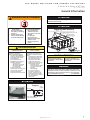
ATTENTION
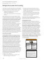
12"
Drain Pan
Union
Coupling
6"
Condensate Drain
Trapping
Slide Out Drain Pan
Union coupling required in installation to
allow removal of drain pan.
ATTENTION
Remove shipping bolt(s) from supply and exhaust fan
assemblies prior to startup.
Use Spreader Bar; Minimum Length = 105”
See Table in IOM for
Minimum Cable Length
See Clevis Detail
Secure Clevis As Shown
At Each Lifting Point
Rigging Instructions
CAUTION/ATTENTION
Single wall heat exchanger,
not suitable for potable water
connection.
Single paroi echangeur, non
approprié pour le raccordment
d'eau potable.
p/n: 95B0034N06

4
2 Series & 4 Series 6-40 Tons
Rev.: 19 Sept 2019
CLIMATEMASTER DOAS
ClimateMaster DOAS
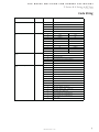
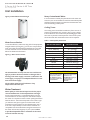
Code String
Component Description Field Code
Product Line 1 D
A
B
H
W
G
X
2 Series 4 Series
06
Nominal 6 ton NA
08
Nominal 7.5 ton NA
10
Nominal 10 ton NA
13
Nominal 12.5 ton NA
15
Nominal 15 ton NA
18
Nominal 17.5 ton NA
20
Nominal 20 ton NA
16
NA Nominal 15 ton
21
NA Nominal 20 ton
25
NA Nominal 25 ton
30
NA Nominal 30 ton
35
NA Nominal 35 ton
40
NA Nominal 40 ton
Seri es (Gen erati o n ) 5 A
A
C
D
E
X
K
L
F
N
X
A
B
C
D
X
Airflow Configuration
8
Vertical Supply / Vertical Return
Vertical Supply / No Return
Horizontal Supply / Vertical Return
Horizontal Supply / No Return
Special Quote
Vo l tage
7
208/3/60
230/3/60
460/3/60
575/3/60
Special Quote
Unit Size
3-4
1 st Gen erati o n
Co m p ress or Typ e
6
Standard High Efficiency Compressors - R-410A All Circuits / 6
Row DX Coils
Variable Speed Compressor - R-410A Lead Circuit / 6 Row DX
Coils
Digital Compressors - R-410A All Circuits / 6 Row DX Coils
Digital Compressor - R-410A Lead Circuit / 6 Row DX Coils
Special Quote
Code Description
Dedicated Outside Air System (DOAS)
Application Type
2
Air-Cooled AC
Water-C oo l ed AC
Air-Cooled HP
Water-So urce HP
Geothermal HP
Special Quote

5
2 Series & 4 Series 6-40 Tons
Rev.: 19 Sept 2019
THE SMART SOLUTION FOR ENERGY EFFICIENCY
climatemaster.com
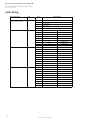
Code String
Component Description Field Code
A
B
C
F
X
2 Series 4 Series
0
None None
A ECW364 NA
B ECW424 NA
C ECW484 ECW484
D ECW486 NA
E NA ECW544
F NA ECW604
G NA ECW664
H NA ECW706
0
A
B
C
D
X
0
A
B
C
D
E
F
G
H
J
K
L
M
S
T
X
Special Quote
1 Row Hot Water Coil (Reheat Position)
2 Row Hot Water Coil (ReHeat Position)
Supplemental Heating
Op tion
12
None
Gas Heat - Low ( Hi/Lo Gas Pressure Switch) - SS409
Gas Heat - Medium ( Hi/Lo Gas Pressure Switch) - SS409
Gas Heat - Medium High ( Hi/Lo Gas Pressure Switch) - SS409
Gas Heat - High ( Hi/Lo Gas Pressure Switch) - SS409
Gas Heat - Low ( Hi/Lo Gas Pressure Switch) - SS304
Gas Heat - Medium ( Hi/Lo Gas Pressure Switch) - SS304
Gas Heat - Medium High ( Hi/Lo Gas Pressure Switch) - SS304
Gas Heat - High ( Hi/Lo Gas Pressure Switch) - SS304
Electric Heat - Low (Open Coil)
Electric heat - Medium (Open Coil)
Electric Heat - Medium High (Open Coil)
Electric Heat - High (Open Coil)
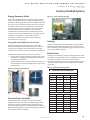
En ergy Reco very Wh eel
Size
10
En ergy Reco very Wh eel
Options
11
None
Defrost Control (Pulsing)
Defrost control (VFD)
Defrost Control (Pulsing) + Bypass Dampers
Defrost Control (VFD) + Bypass Dampers
Special Quote
Code Description
Dam pers
9
Motorized O.A & R.A. 2-Position Dampers
Motorized O.A. 2-Position Damper
Modulating Enthalpy Economizer
No Dampers
Special Quote

6
2 Series & 4 Series 6-40 Tons
Rev.: 19 Sept 2019
CLIMATEMASTER DOAS
ClimateMaster DOAS
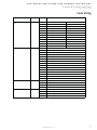
Code String
Component Description Field Code
0
A
B
C
X
2 Series 4 Series
A
(1) DDP105-9-120 NA
B
(1) DDP150-9-120 (1) DDP150-9-120
C
(1) DDP165-9-120 (1) DDP165-9-120
D
(1) DDP182-9-120 (1) DDP182-9-120
E
NA (1) DDP222-9-120
F
NA (1) DDP245-9-120
G
NA (1) DDP270-9-120
X
Special Quote Special Quote
K
(1) 1 HP 1800 RPM (1) 1 HP 1800 RPM
L
(1) 2 HP 1800 RPM (1) 2 HP 1800 RPM
M
(1) 3 HP 1800 RPM (1) 3 HP 1800 RPM
N
(1) 5 HP 1800 RPM (1) 5 HP 1800 RPM
P
(1) 7.5 HP 1800 RPM (1) 7.5 HP 1800 RPM
Q
(1) 10 HP 1800 RPM (1) 10 HP 1800 RPM
R
(1) 15 HP 1800 RPM (1) 15 HP 1800 RPM
S
(1) 20 HP 1800 RPM (1) 20 HP 1800 RPM
T
(1) 25 HP 1800 RPM (1) 25 HP 1800 RPM
X
Special Quote Special Quote
2 Series 4 Series
0
None None
A
(1) DDP105-9-120 NA
B
(1) DDP150-9-120 (1) DDP150-9-120
C
(1) DDP165-9-120 (1) DDP165-9-120
D
(1) DDP182-9-120 (1) DDP182-9-120
E
NA (1) DDP222-9-120
F
NA (1) DDP245-9-120
G
NA (1) DDP270-9-120
X
Special Quote Special Quote
Supply Blower
14
Supply Blower Motor
Power Exhaust Blower
16
Code Description
Control Method For
Supplemental Heating Option
13
None
Modulating control for Gas Heat (No Compressor Running
Simultaneously)
SCR control for Electric Heat (No Compressor Running
Simultaneously)
Modulating Control for Hot Water Coils (No Compressor Running
Special Quote

7
2 Series & 4 Series 6-40 Tons
Rev.: 19 Sept 2019
THE SMART SOLUTION FOR ENERGY EFFICIENCY
climatemaster.com
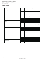
Code String
Component Description Field Code
2 Series 4 Series
0
None None
K
(1) 1 HP 1800 RPM (1) 1 HP 1800 RPM
L
(1) 2 HP 1800 RPM (1) 2 HP 1800 RPM
M
(1) 3 HP 1800 RPM (1) 3 HP 1800 RPM
N
(1) 5 HP 1800 RPM (1) 5 HP 1800 RPM
P
(1) 7.5 HP 1800 RPM (1) 7.5 HP 1800 RPM
Q
(1) 10 HP 1800 RPM (1) 10 HP 1800 RPM
R
(1) 15 HP 1800 RPM (1) 15 HP 1800 RPM
S
(1) 20 HP 1800 RPM (1) 20 HP 1800 RPM
T
(1) 25 HP 1800 RPM (1) 25 HP 1800 RPM
X
Special Quote Special Quote
A
B
C
D
E
F
G
2
3
4
5
6
7
8
X
0
A
B
X
0
A
B
X
Liquid Subcooling
20
None
Liquid Subcooling Constant - All Circuits
Liquid Subcooling Switchable - All Circuits
Special Quote
2 In. MERV 8 plus 4 In. MERV 8 With Dirty Filter Indicator
2 In. MERV 8 plus 4 In. MERV 13 With Dirty Filter Indicator
2 In. MERV 8 plus 4 In. MERV 14 With Dirty Filter Indicator
Special Quote
Hot Gas Reheat
19
None
Modulating HGRH - All Circuits
Modulating HGRH - Lead Circuit
Special Quote
Code Description
Power Exhaust Blower
Motor
17
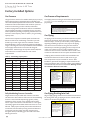
Filters
18
2 In. Pleated MERV 8 Filters
4 In. Pleated MERV 8 Filters
4 In. Pleated MERV 13 Filters
4 In. Pleated MERV 14 Filters
2 In. MERV 8 plus 4 In. MERV 8
2 In. MERV 8 plus 4 In. MERV 13
2 In. MERV 8 plus 4 In. MERV 14
2 In. Pleated MERV 8 Filters With Dirty Filter Indicator
4 In. Pleated MERV 8 Filters With Dirty Filter Indicator
4 In. Pleated MERV 13 Filters With Dirty Filter Indicator
4 In. Pleated MERV 14 Filters With Dirty Filter Indicator

8
2 Series & 4 Series 6-40 Tons
Rev.: 19 Sept 2019
CLIMATEMASTER DOAS
ClimateMaster DOAS
Code String
Component Description Field Code Code Description
0
None
A Hot Gas Bypass - All Circuits
X Special Quote
0
None
A Condenser Coil Coating
C Condenser Coil Hail Guard
E Condenser Coil Coating and Hail Guard
X Special Quote
0
None
A Evaporator Coil Coating
B Stainless Steel Evap Coil Casing
C Evaporator Coil Coating & Stainless Steel Evap Coil Casing
X Special Quote
DDC Control 24 A Standard Controls (DDC)
A Makeup Air Control
B Recirculating Unit Control
C CO2 Demand Control
D VAV controls
X Special Quote
0
None
A Airflow Measurement Readout (Climatemaster DDC Control)
X Special Quote
0
None
A Phase Monitor
X Special Quote
0
None
A Firestat + Smoke Detector Terminal
X Special Quote
Phase Monitor
27
Firestat + Smoke
Detector Terminal
28
Operating Logic
25
Airflow Measurement
26
Hot Gas Bypass
21
Condenser Contruction
Options
22
Evaporator Contruction
Options
23

9
2 Series & 4 Series 6-40 Tons
Rev.: 19 Sept 2019
THE SMART SOLUTION FOR ENERGY EFFICIENCY
climatemaster.com
Code String
Code String
Page 1 of 2 8/1/2014
Component Description Field Code
Code Description
0
A
B
X
0
A
B
C
D
E
F
X
60 Amp Non-Fused Main Disconnect
None
30 Amp Non-Fused Main Disconnect
100 Amp Non-Fused Main Disconnect
200 Amp Non-Fused Main Disconnect
400 Amp Non-Fused Main Disconnect
600 Amp Non-Fused Main Disconnect
Special Quote
GFI Outlet
29
None
115 V GFI Outlet (field powered)
115 V GFI Outlet (unit powered)
Special Quote
30Disconnect

10
2 Series & 4 Series 6-40 Tons
Rev.: 19 Sept 2019
CLIMATEMASTER DOAS
ClimateMaster DOAS
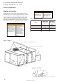
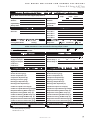
Pre-Installation
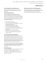
Receiving Inspection
Storage
Warranty
against the bill of lading to be sure all crates and cartons
have been received. All units should be carefully inspected
for any damage incurred during shipment. The carrier must
copies of the bill of lading and complete a carrier inspection
necessary claims with the carrier. Before unloading the
unit, check the unit nameplate to make sure the voltage
complies with the power supply available.
Handling of Units
Rigging holes for clevis hangers are provided on the unit
base for placement of unit with a crane. Please see Rigging
and Handling on page 22.
If installation will not occur immediately following delivery
• Units must be placed on a level ground surface.
• Provide proper drainage around the unit to prevent
• All doors must be closed and latched.
• Units must be covered and protected from construction
•
the units.
Climatemaster IO&M manuals.
ATTENTION
This manual is specifi cally intended for qualifi ed installation
and service agencies trained to perform the installation and
service of the rooftop unit.

11
2 Series & 4 Series 6-40 Tons
Rev.: 19 Sept 2019
THE SMART SOLUTION FOR ENERGY EFFICIENCY
climatemaster.com
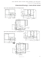
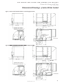
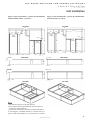
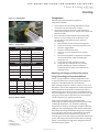
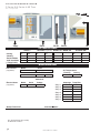
Dimensional Drawings - 2 Series Air Cooled
Figure 1 - Air Cooled Standard Cabinet - Vertical Supply, No Return
96"
40"
14"
Horizontal
Gas Inlet
100"
End View
65"
70"
26"
102"
106"
8"
9"
Side View
Bottom View
8.75"
43"
14"
6"
11"
6.5"
2. TYP Baseframe
60"
25.75"Gas Through
Curb
Supply
Power and Control
Through Curb
Ø3 TYP
Figure 2 - Air Cooled Standard Cabinet - Vertical Supply & Return
End View
100"
96"
40"
14"
Horizontal
Gas Inlet
65"
8"
9"
70"
26"
102"
106"
Side View
Gas Inlet
Side View
25.75"
8.75"
43"
50"
18"
5"Power and Control
Through Curb
Ø3 TYP
2"
Supply
Return
2. TYP Baseframe
6"
6.5"
11"
14"
Bottom View
60"
Gas Through
Curb

12
2 Series & 4 Series 6-40 Tons
Rev.: 19 Sept 2019
CLIMATEMASTER DOAS
ClimateMaster DOAS
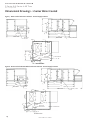
Dimensional Drawings - 2 Series Air Cooled
Horizontal
Gas Inlet
96"
100"
End View
40"
14"
Side View
171"
135"
131"
70"
9"
8"
65"
25.75"
43"
50"
18"
36"
Power and Control
Through Curb
Ø3 TYP
2"
Supply
Return
2. TYP Baseframe
Gas Through
Curb
6"
60"
6.5"
11"
14"
Bottom View
8.75"
Figure 3 - Air Cooled with Power Exhaust - Vertical Supply & Return
End View
96"
40"
14"
100"
Horizontal
Gas Inlet
Side View
65"
70"
102"
106"
143"
8"
9"
6.5"
6.5"
25.75"
8.75"
43"
14"
60"
11"
6.5"
50"
18"
Power and Control
Through Curb
Ø3 TYP
Gas Through
Curb
2"
5"
6"
Supply
Return
2. TYP Baseframe
Bottom View
Figure 4 - Air Cooled with ECW Wheel and Power Exhaust - Vertical Supply & Return

13
2 Series & 4 Series 6-40 Tons
Rev.: 19 Sept 2019
THE SMART SOLUTION FOR ENERGY EFFICIENCY
climatemaster.com
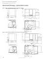
Dimensional Drawings - 2 Series Water Cooled
Figure 5- Water Cooled Standard Cabinet - Vertical Supply, No Return
End View
96"
100"
40"
14"
Horizontal
Gas Inlet
Side View
106"
102"
70"
26"
9"
8"
64"
Bottom View
25.75"
43"
Power and Control
Through Curb
Ø3 TYP
Supply
Gas Through
Curb
6"
60"
8.75"
12"
11"
14"
6.5"
6"
46"
2. TYP Baseframe
Water Inlet
Water Outlet
End View
100"
96"
40"
14"
Horizontal
Gas Inlet
Side View
106"
102"
70"
26"
9"
64"
8"
Figure 6 - Water Cooled Standard Cabinet - Vertical Supply & Return
Bottom View
Horizontal
Gas Inlet
Gas Through
Curb
60"
8.75"
2"
5"
43"
18"
50"
25.75"
14"
6"
11"
46"
6.5"
12"
2. TYP Baseframe
6"
Power and Control
Through Curb
Ø3 TYP
Water Inlet
Water Outlet
Supply
Return

14
2 Series & 4 Series 6-40 Tons
Rev.: 19 Sept 2019
CLIMATEMASTER DOAS
ClimateMaster DOAS
Dimensional Drawings - 2 Series Water Cooled
Figure 8 - Water Cooled with ECW Wheel and Power Exhaust - Vertical Supply & Return
End View
100"
96"
40"
14"
Horizontal
Gas Inlet
64"
8"
9"
70"
131"
135"
171"
Side View
6"
11"
14"
25.75"
43"
8.75"
2"
50"
18"
36"
2. TYP Baseframe
Power and Control
Through Curb
Ø3 TYP
12"
6.5"
46" 6"
Bottom View
Supply
Return
Water Inlet
Water Outlet
Figure 7 - Water Cooled with Power Exhaust - Vertical Supply & Return
96"
100"
40"
14"
End View
Horizontal
Gas Inlet
Side View
106"
143"
102"
70"
9"
64"
8"
Gas Through
Curb
60"
8.75"
2"
Supply
Return
43"
50"
25.75"
14"
6"
5"
11"
46"
6.5"
12"
18"
2. TYP Baseframe
6"
Bottom View
Power and Control
Through Curb
Ø3 TYP
Water Inlet
Water Outlet

15
2 Series & 4 Series 6-40 Tons
Rev.: 19 Sept 2019
THE SMART SOLUTION FOR ENERGY EFFICIENCY
climatemaster.com
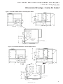
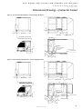
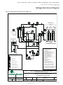
Dimensional Drawings - 4 Series Air Cooled
Figure 9 - Air Cooled Standard Cabinet - Vertical Supply, No Return
Figure 10 - Air Cooled Standard Cabinet - Vertical Supply & Return
13"
14"
40"
96"
100"
End View
Optional Gas Furnace
Horizontal Connection
Side View
90"
9"
30"
75"
50"
5"
7"
7" 7"
46"
56"
14"
20"
5"
24"
3" 2.5"
95"
136"
140"
184"
Side View
Bottom View
2. TYP Baseframe
Gas Through
Curb
Supply
Return
Power and Control
Through Curb
Ø4 TYP
Water Inlet
Water Outlet
13"
96"
100"
End View
Optional Gas Furnace
Horizontal Connection
14"
40"
Side View
90"
9"
95"
136"
140"
184"
Side View
30"
3"
Supply
5"
14"
7"
20" 7"
46"
Bottom View
2. TYP Baseframe
Gas Through
Curb
Power and Control
Through Curb
Ø4 TYP
75"

16
2 Series & 4 Series 6-40 Tons
Rev.: 19 Sept 2019
CLIMATEMASTER DOAS
ClimateMaster DOAS
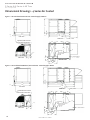
Dimensional Drawings - 4 Series Air Cooled
Figure 11 - Air Cooled with Power Exhaust - Vertical Supply & Return
Figure 12 - Air Cooled with ECW Wheel, Power Exhaust - Vertical Supply & Return
13"
96"
100"
End View
Optional Gas Furnace
Horizontal Connection
14"
40"
Side View
90"
9"
95"
136"
140"
184"
Side View
30"
3"
2.5"
24"
Supply
Return
5"
5"
75"
50"
2. TYP Baseframe
Bottom View
14"
7"
20"
7"
46"
Gas Through
Curb
Power and Control
Through Curb
Ø4 TYP
13"
96"
100"
End View
Optional Gas Furnace
Horizontal Connection
Side View
40"
14"
90"
9"
95"
164"
168"
212"
Side View
30"
3"
2.5"
24"
Supply
Return
5"
75"
50"
33"
2. TYP Baseframe
Gas Through
Curb
Power and Control
Through Curb
Ø4 TYP
14"
7"
20"
7"
46"
Bottom View

17
2 Series & 4 Series 6-40 Tons
Rev.: 19 Sept 2019
THE SMART SOLUTION FOR ENERGY EFFICIENCY
climatemaster.com
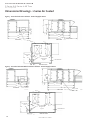
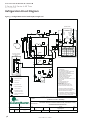
Dimensional Drawings - 4 Series Water Cooled
Figure 13 - Water Cooled Standard Cabinet - Vertical Supply, No Return
Figure 14 - Water Cooled Standard Cabinet - Vertical Supply & Return
Figure 14 - Water Cooled Standard Cabinet - Vertical Supply & Return
13"
96"
100"
End View
Optional Gas Furnace
Horizontal Connection
Side View
14"
40"
Figure 14 - Water Cooled Standard Cabinet - Vertical Supply & Return
89"
9"
95"
136"
140"
184"
Side View
30"
3"
5"
11.5"
7"
7"
7"
7"
20"
46"
82"
Bottom View
2. TYP Baseframe
75"
Supply
Gas Through
Curb
Water Inlet
Water Outlet
Power and Control
Through Curb
Ø4 TYP
13"
96"
100"
End View
Optional Gas Furnace
Horizontal Connection
Side View
40"
14"
89"
9"
95"
136"
140"
184"
Side View
30"
2.5"
24"
3"
Supply
Return
5"
5"
75"
50"
Gas Through
Curb
Power and Control
Through Curb
Ø4 TYP
Water Inlet
Water Outlet
2. TYP Baseframe
Bottom View
7"
7"
7"
7"
11.5"
20"
46"
82"

18
2 Series & 4 Series 6-40 Tons
Rev.: 19 Sept 2019
CLIMATEMASTER DOAS
ClimateMaster DOAS
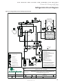
Figure 15 - Water Cooled with Power Exhaust - Vertical Supply & Return
Dimensional Drawings - 4 Series Water Cooled
Figure 15 - Water Cooled with Power Exhaust - Vertical Supply & Return
13"
96"
100"
End View
Optional Gas Furnace
Horizontal Connection
14"
40"
Side View
Figure 15 - Water Cooled with Power Exhaust - Vertical Supply & Return
89"
9"
95"
136"
140"
184"
Side View
30"
3"
2.5"
24"
Supply
Return
50"
75"
11.5"
7"
7"
7"
7"
20"
46"
82"
Bottom View
2. TYP Baseframe
5"
Gas Through
Curb
Power and Control
Through Curb
Ø4 TYP
Water Inlet
Water Outlet
Figure 16 - Water Cooled with ECW Wheel, Power Exhaust - Vertical Supply & Return
13"
96"
100"
End View
Optional Gas Furnace
Horizontal Connection
14"
40"
Side View
89"
9"
95"
164"
168"
212"
Side View
30"
3" 2.5"
24"
Supply
Return
75"
50"
11.5"
7"
7"
7"
7"
Gas Through
Curb
Power and Control
Through Curb
Ø4 TYP
Water Inlet
Water Outlet
33"
Bottom View
20"
46"
82"
2. TYP Baseframe
5"

19
2 Series & 4 Series 6-40 Tons
Rev.: 19 Sept 2019
THE SMART SOLUTION FOR ENERGY EFFICIENCY
climatemaster.com
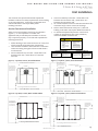
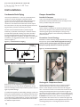
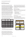
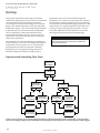
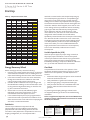
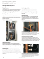
Unit Installation
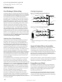
Service Clearance and Ventilation
Allow service and ventilation clearances as indicated in
Figures 17 - 20. It is imperative to consider each
application and provide adequate ventilation or the unit
may not perform properly. Local codes will supersede the
1.
2.
not obstructed.
3.
each unit.
The customer must provide trained and experienced
installers to follow local safety requirements when installing
or servicing equipment. Conforming to applicable local
and national codes is the responsibility of the
installing contractor.
62" Clearance with
Control Panel & Gas/
Electric/Steam Heat
42" Clearance with
Control Panel Only
54"
54"
54"
Figure 17 - Top View, 2 Series, Air Cooled Cabinet
Figure 18 - Top View, 2 Series, Water Cooled Cabinet
4.
between the unit and the wall.
5. Air Cooled installations must be unobstructed above the
condenser fan(s) to allow vertical air discharge.
6.
building codes which may require additional clearance.
7. To maintain adequate head pressure control at low
Supply Blower/
Power Exhaust/
Motor Service
Clearance
Gas/Electric Heat
Clearance
Condenser Access
30"
54"
54"
Exhaust Fan/Motor
Service Clearance
Supply Blower/
Power Exhaust/
Motor Service
Clearance
62" Clearance with
Control Panel & Gas/
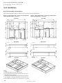
Electric/Steam Heat
42" Clearance with
Control Panel Only
90" (Gas/Electric Heat Only)
60"
24"
60"
54"
90" (Gas/Electric Heat Only)
Exhaust Fan/Motor
Service Clearance
90" Clearance with
Control Panel & Gas/
Electric/Steam Heat
45" Clearance with
Control Panel Only
Supply Blower/
Power Exhaust/
Motor Service
Clearance
Figure 20 - Top View, 4 Series, Water Cooled Cabinet
CAUTION/ATTENTION
CAUTION/ATTENTION
What to do if you smell gas:
• Open windows if the
appliance is located
indoors
• Don’t touch electrical
switches
• Extinguish any open
fl ame
• Immediately call gas
supplier
Que faire si vous sentez une
odeur de gaz:
• Ouvrez les fenêtres si
l’appareil se trouve à
l’intérieur
• Ne touchez pas aux
interrupteurs électriques
• Éteindre toute fl amme
• Appelez immédiatement
votre fournisseur de gaz
CAUTION/ATTENTION
The presence of chlorine
vapors in the combustion air
supplied to gas-fi red heaters
presents a substantial
corrosion hazard.
La présence de vapeurs
de chlore dans l’air de
combustion fourni à ce four
a un haut risque de cor-
rosion.
CAUTION/ATTENTION
Flue gases must be directed
away from combustion air
inlets to avoid recirculation
into combustion air supply.
Les gaz de combustion
doivent être dirigés loin de
prises d’air de combustion
pour éviter la recirculation
dans l’alimentation en air de
combustion.
90" (Gas/Electric Heat Only)
Exhaust Fan/Motor
Service Clearance
60"
24"
60"
54"
90" Clearance with
Control Panel & Gas/
Electric/Steam Heat
45" Clearance with
Control Panel Only
Supply Blower/
Power Exhaust/
Motor Service
Clearance
Clearance
Figure 19 - Top View, 4 Series, Air Cooled Cabinet
2. TYP Baseframe
La page est en cours de chargement...
La page est en cours de chargement...
La page est en cours de chargement...
La page est en cours de chargement...
La page est en cours de chargement...
La page est en cours de chargement...
La page est en cours de chargement...
La page est en cours de chargement...
La page est en cours de chargement...
La page est en cours de chargement...
La page est en cours de chargement...
La page est en cours de chargement...
La page est en cours de chargement...
La page est en cours de chargement...
La page est en cours de chargement...
La page est en cours de chargement...
La page est en cours de chargement...
La page est en cours de chargement...
La page est en cours de chargement...
La page est en cours de chargement...
La page est en cours de chargement...
La page est en cours de chargement...
La page est en cours de chargement...
La page est en cours de chargement...
La page est en cours de chargement...
La page est en cours de chargement...
La page est en cours de chargement...
La page est en cours de chargement...
La page est en cours de chargement...
La page est en cours de chargement...
La page est en cours de chargement...
La page est en cours de chargement...
-
 1
1
-
 2
2
-
 3
3
-
 4
4
-
 5
5
-
 6
6
-
 7
7
-
 8
8
-
 9
9
-
 10
10
-
 11
11
-
 12
12
-
 13
13
-
 14
14
-
 15
15
-
 16
16
-
 17
17
-
 18
18
-
 19
19
-
 20
20
-
 21
21
-
 22
22
-
 23
23
-
 24
24
-
 25
25
-
 26
26
-
 27
27
-
 28
28
-
 29
29
-
 30
30
-
 31
31
-
 32
32
-
 33
33
-
 34
34
-
 35
35
-
 36
36
-
 37
37
-
 38
38
-
 39
39
-
 40
40
-
 41
41
-
 42
42
-
 43
43
-
 44
44
-
 45
45
-
 46
46
-
 47
47
-
 48
48
-
 49
49
-
 50
50
-
 51
51
-
 52
52


ClimateMaster Dedicated Outside Air Systems Le manuel du propriétaire
- Taper
- Le manuel du propriétaire
dans d''autres langues
Documents connexes
-
ClimateMaster CP, MH, MV, PDE, EH, EV Install Manual
-
-
ClimateMaster Horizontal/Vertical WSHP Install Manual
-
-
-
Autres documents
-
STA-RITE MIB0715B, MIB0715S Intelliboost Le manuel du propriétaire
-
Promax RG5410A-E Manuel utilisateur
-
GE AUH2436ZGDA Guide d'installation
-
NAPOLEON NT13A018C-1 Manuel utilisateur
-
GE Caliber Mode d'emploi
-
Maytag C7B(A,H)M0 Guide d'installation
-
-
-
Trane Horizon OANE360A Installation, Operation and Maintenance Manual
-
Panasonic S-07MD1U6 Guide d'installation