
JB INDUSTRIES
OPERATING MANUAL
ELIMINATOR
®
DV-6E-250SP
Spark-Proof
DV-6E
ELIMINATOR 2-STAGE DIRECT DRIVE
VACUUM PUMP SERIES
CONTENTS
Introduction . . . . . . . . . . . . . . . . . . . . . . . . . . 2
Motor Specifications . . . . . . . . . . . . . . . . . . . . . . 2
Operation. . . . . . . . . . . . . . . . . . . . . . . . . . . . 2
Pump Maintenance. . . . . . . . . . . . . . . . . . . . . . . 2
Adding Oil . . . . . . . . . . . . . . . . . . . . . . . . . 2
Changing Oil . . . . . . . . . . . . . . . . . . . . . . . . 2
Flushing Oil . . . . . . . . . . . . . . . . . . . . . . . . 2
ELIMINATOR® Pump Models . . . . . . . . . . . . . . . . . 3
Cord Options . . . . . . . . . . . . . . . . . . . . . . . .11
Keeping the Life in Your Pump—Tech Tips From the Pros . . 4
Using Charging and Testing Hoses for Evacuation . . . . . . 5
Digital Micron Gauges . . . . . . . . . . . . . . . . . . . . . 6
Inaccurate Readings . . . . . . . . . . . . . . . . . . . . 6
Erratic Readings . . . . . . . . . . . . . . . . . . . . . . 6
Breaking Vacuum. . . . . . . . . . . . . . . . . . . . . . 7
Cross Reference of Vacuum Measurements . . . . . . . . 7
Troubleshooting and Repair . . . . . . . . . . . . . . . . . . 8
Repair Parts for DV-3E, DV-4E and DV-6E Series Pumps . 9
Flexible Couplers. . . . . . . . . . . . . . . . . . . . . .10
Replacing Coupler (Motor Removed) . . . . . . . . . . .10
Sight Glass Repair . . . . . . . . . . . . . . . . . . . . .10
Tethered Safety Exhaust Caps . . . . . . . . . . . . . . .10
Cartridge Repair and Replacement . . . . . . . . . . . . .10
Accessories . . . . . . . . . . . . . . . . . . . . . . . . . .12
Return for Repair . . . . . . . . . . . . . . . . . . . . . . . .12
Warranty . . . . . . . . . . . . . . . . . . . . . . . . . . . .12
WARNING: UNIT DRAINED OF OIL
FOR SHIPMENT. DO NOT OPERATE
WITHOUT ADDING OIL.

2JB INDUSTRIES • ELIMINATOR OPERATING MANUAL • 800.323.0811 • [email protected] • JBIND.COM
INTRODUCTION
Each ELIMINATOR® vacuum pump has been factory tested to guarantee 25
microns (25,400 Microns = 1 Inch of Hg) or better, and listed CFM performance.
The serial number has been recorded. Complete and mail the enclosed Warranty
Registration Card or register online at www.jbind.com to validate your warranty.
NOTE: ELIMINATOR® pumps are not to be used on Ammonia or Lithium Bromide
(salt water) systems. Pump maintenance is the responsibility of the owner.
MOTOR SPECIFICATIONS
Pump and oil must be above 30°F. Line voltage must be equal to motor nameplate
±10%. Normal operating temperature is approximately 160°F, which is hot to
the touch. Line voltage and ambient conditions can slightly affect this. Motor has
automatic resetting thermal overload protection.
The ELIMINATOR® is designed for continuous duty and will run for extended
periods without overheating.
International Dual Voltage Pump
ELIMINATOR® -250 Series models feature a dual voltage motor with switch and
removable, interchangeable power cord. Specify US, EU, UK, AU or BR plug type.
Spark-Proof Pump
ELIMINATOR® -250SP Series models feature a spark-proof, dual voltage
motor with switch and removable, interchangeable power cord for use with A2L
refrigerant gases such as R32 and 1234yf, DV-6E-250SP.
OPERATION
The following procedures will prevent oil from being drawn into the pump cartridge
and creating hard start-up.
Start-up: Close both sides of manifold and make connection to vacuum pump or
auxiliary blank-off equipment. Start pump.
Shutdown: Crack open unused port to break vacuum. Allow pump to run 2-3
seconds. Shutdown and remove hose connections and cap intakes.
PUMP MAINTENANCE
In order to make the best use of your investment, familiarize yourself with the
features and operating instructions before starting pump. With routine care and
following proper maintenance guidelines, your ELIMINATOR® will give you years
of reliable service. ELIMINATOR® pumps are designed for deep vacuum work in air
conditioning and refrigeration systems.
For a complete overview of proper care and pump maintenance, refer to the
Keeping the Life in your Pump section on page 4.
Adding Oil
Step 1: Slowly add oil until level rises to the top of the oil level line. (Figure 1)
Step 2: Replace oil fill plug.
If oil level is too low, you will hear air out of the exhaust. If oil level is too high,
excess oil will be blown out of the exhaust.
IMPORTANT: Use oil specifically refined for deep vacuum pumps. Using oil
not refined for deep vacuum pumps and/or operating with contaminated oil will
void warranty.
Pump oil should be changed after each use. If system is heavily contaminated,
oil may have to be changed several times during evacuation. After initial fill up,
it is best to check oil level with pump running.
After evacuation, oil contains rust forming water and corrosive acids. Drain
immediately while pump is warm.
Changing Oil
To reach deep vacuum, ELIMINATOR® pumps need clean, moisture-free oil
throughout evacuation. Care should be taken to avoid contact on skin and clothing
when changing oil. Used oil should be disposed of in the DV-T1 TANK Oil Caddy
after every evacuation while the pump is warm and the oil is thin.
Step 1: Place the TANK on a level surface. Unscrew black plug in drain base
to open.
Step 2: Place vacuum pump in the cradle and drain pump.
Step 3: When pump has finished draining, replace black plug. The TANK can hold
up to five oil changes.
Step 4: Close oil drain valve on pump. Remove oil fill plug and fill to top of oil
level line with BLACK GOLD Pump Oil (Figure 1). Replace oil fill plug.
Flushing Oil
Step 1: Always drain pump before flushing. If the oil is badly contaminated,
flushing may be necessary.
Step 2: Slowly pour 1/3 to 1/2 cup of BLACK GOLD Pump Oil into the intake
connection while pump is running.
Step 3: Repeat as required until contamination is removed from oil reservoir,
pump rotors, vanes and housing.
Step 4: Dispose of all oil used in flushing of pump.
WARNING: DO NOT START PUMP BEFORE ADDING OIL
Black Gold Pump Oil
Acts as a coolant, lubricant and
sealant—simultaneously.
DV-T1 Tank Pump Oil Caddy
• Change oil between jobs
• No more mess and spills
• Easy, convenient, and portable
• Capacity for five oil changes
WARNING: UNIT DRAINED OF OIL FOR SHIPMENT.
DO NOT OPERATE WITHOUT ADDING OIL.
IMPORTANT
Figure 1
IMPORTANT: OIL LEVEL MUST BE ABOVE
HALF WAY IN SIGHT GLASS

3
JB INDUSTRIES • ELIMINATOR OPERATING MANUAL • 800.323.0811 • [email protected] • JBIND.COM
ELIMINATOR® PUMP MODELS
*Specify plug type when ordering; -250 for US, -250EU for EU, -250UK for UK.
ELIMINATOR® DUAL VOLTAGE AND SPARK-PROOF
DV-3E-250 DV-4E-250 DV-6E-250 DV-6E-250SP
MOTOR 1/2 HP, 1725/1425 RPM 1/2 HP, 1725/1425 RPM 1/2 HP, 1725/1425 RPM 1/2 HP, 1725/1425 RPM
VOLTAGE 115v/60Hz, 230v/50Hz 115v/60Hz, 230v/50Hz 115v/60Hz, 230v/50Hz 115v/60Hz, 230v/50Hz
PLUG US 220v US 220v US 220v US 220v
PLUG OPTIONS* US/EU/UK/AU/BR US/EU/UK/AU/BR US/EU/UK/AU/BR US/EU/UK/AU/BR
ELIMINATOR® PUMPS
DV-3E DV-4E DV-6E
CFM 3 CFM (85 l/m) 4 CFM (113 l/m) 6 CFM (170 l/m)
MOTOR 1/2 HP, 1725 RPM 1/2 HP, 1725 RPM 1/2 HP, 1725 RPM
VOLTAGE 115v/60Hz 115v/60Hz 115v/60Hz
INTAKE PORT 1/4" x 3/8" 1/4" x 3/8" 1/4" x 3/8"
OIL CAPACITY 28oz (828cc) 25oz (739cc) 25oz (739cc)
SHIPPING DIMS 17-5/8" x 9-1/8" x 14" 17-5/8" x 9-1/8" x 14" 17-5/8" x 9-1/8" x 14"
WEIGHT 29lbs (13.2kg) 30lbs (13.6kg) 30lbs (13.6kg)
Exhaust
Intake
Oil Fill Plug
(Do not wrench down
or use sealant on threads)
Oil Drain Valve
(Close drain finger-tight)
DV-6E Model Shown
US Cord
PR-110 (110v)
PR-230 (230v)
EU Cord
PR-136 UK Cord
PR-236 AU Cord
PR-336 BR Cord
PR-436
Cord Options

4JB INDUSTRIES • ELIMINATOR OPERATING MANUAL • 800.323.0811 • [email protected] • JBIND.COM
KEEPING THE LIFE IN YOUR PUMP—
TECH TIPS FROM THE PROS
Remember to change the oil. JB recommends changing oil after every evacuation
and for larger jobs, it may need to be changed a few times. Hydrofluoric and
hydrochloric acids and moisture collect in the oil. Left sitting in a pump, they act
as an abrasive on internal surfaces, rusting and corroding them.
Cleaning and Testing Your Vacuum Pump
One of the easiest ways to spot if your pump is in need of a good cleaning is to
look at the sight glass. If the oil looks milky, rusty, or full of debris, then the inside
of the pump is in worse shape (Figure 2).
To clean, start the vacuum pump and allow it to run for about 15 minutes to warm
up the oil. Make sure that you have allowed enough working room to safely drain
and capture the oil. After the oil has stopped dripping, tilt the pump forward to
remove any remaining excess oil (Figure 3). Let sit for a few minutes and return
the pump to its normal running position. Repeat tilting forward. Close drain valve.
Dispose of contaminated oil properly.
Once the oil has been completely removed, stand the pump on the nose of the
cover (Figure 4) and remove either the two rubber feet from the bottom of the
pump or remove pump base (depends on the age of the pump which option
is available).
Next, turn the pump on to the motor end (Figure 5) and remove the 6 socket
head cover screws holding the cover in place (Figure 6). Remove the cover from
the pump and wipe the inside surface with a dry, clean rag. The sight glass is more
difficult to clean. Try pouring in some solvent and using a pipe cleaner.
Next, remove the oil deflector which is held in place with a socket head screw
(Figure 7). Wipe with a clean, dry rag. If needed, a wire brush can be used
to clean any discoloration to metal parts (this will not affect the pump’s
performance once the cleaning is complete). Remove the cover seal and clean
cover seal (Figure 8). Wipe the outside of the cartridge’s surfaces with a clean,
dry rag. A wire brush can be used on all surfaces including the exhaust valve and
the intake relief valve. If they are discolored, they will still perform fine.
DO NOT
Disturb the four cartridge bolts or the two smaller hex head screws
(Figure 8). These are the setting screws.
If the intake relief valve set or the exhaust valve set is damaged and needs
replacing, these items can be ordered through your local wholesaler under JB Part
Number PR-18. It is best to replace after completing the cleaning of the cartridge.
Pay attention to the order in which they are assembled for correct re-installation.
Reassemble the oil deflector (Figure 9). Clean out the channel for the cover seal
with a clean, dry rag and smear some grease into the channel. This will help hold
the cover seal in place for reinstallation of the cover. If the cover seal seems a little
tight, stretch the seal a little and try again. All seals in JB pumps are designed
to be reused. Reset the cover in place and replace the cover screws. Tighten in a
crisscross pattern. Reattach feet or base.
Next, return the pump to its normal running position and place where you drained
the oil. Open the drain valve, the top port on the intake, and the isolation valve.
Have 1/3 cup of clean oil ready. Start the pump and pour the clean oil into the
intake port. Let the pump run for 5 to 6 seconds and then shut the pump off. Drain
the oil, tipping the pump forward (Figure 3) to completely drain. Close the drain
valve and dispose of spent oil properly after the flushing is complete.
Figure 2
Figure 4
Figure 6
Figure 8
Figure 3
Figure 5
Figure 7
Figure 9
JB PUMPS ARE NOT TO BE USED ON AMMONIA OR LITHIUM BROMIDE (SALT WATER)
SYSTEMS. PUMP MAINTENANCE IS THE RESPONSIBILITY OF THE OWNER.
IMPORTANT

5
JB INDUSTRIES • ELIMINATOR OPERATING MANUAL • 800.323.0811 • [email protected] • JBIND.COM
Now, fill the pump to the proper oil level and allow the pump to run with the
isolation valve closed for 3 or 4 minutes to warm up the oil. Check all o-ring caps
for dirt and proper seal. Connect a vacuum gauge (JB recommends the DV-22N,
DV-41 or DV-40S) directly to the 1/4" port on the intake tee (Figure 8). Do not
use a charging line. Open the isolation valve.
DO NOT
USE A CHARGING LINE
A charging line, especially a new line, will give you a higher
micron reading because you are reading the environment
inside the hose (Figure 11).
Figures 11 and 12 are the same, but (Figure 10) is a direct connection hook-up
and (Figure 11) is a connection through a new charging line. Both hook-ups are
allowed to run the same length of time, but (Figure 10) is at 20 microns while
(Figure 11) is at 297. If left on, the charging line hook-up will come down in its
micron reading, but it will take a much greater period of time. If the hose is cleaned
out with alcohol and vacuumed for a long period of time, the micron reading will
go lower.
USING CHARGING AND TESTING
HOSES FOR EVACUATION
If a leak is suspected: An evacuation/dehydration hook-up requires a leak-proof
design in all of the components. Only soft copper tubing, pure rubber hoses, or
flexible metal hoses are absolutely vacuum tight. Charging hoses are designed for
positive pressure. Even with the advanced technology of today’s hoses, permeation
through the hose compound still exists (Figure 12).
If you have blanked-off your pump to check pressure rise and your hoses and
connections are not leak-free, the atmosphere will permeate to the lower pressure
in the hoses. Your reading will slowly rise and you will spend time looking for
system leaks.
PUMP CONNECTIONS
Moving to the connections on the pump, the factory intake is loctited into place
and each pump is tested for leaks. If this is not disturbed, the chances of a leak are
virtually non-existent. Any leak would come from the connection at the port being
used and to the connection to the system.
One of the most common errors with both the o-ring and the gasket couplers is
the wrenching down of these couplers with a pair of pliers or channel locks
(Figure 13). Please refer to our Principles of Deep Vacuum article. This article
can be found at www.jbind.com under Product Support.
DO NOT
Wrench down on coupler (Figure 13).
The article, Principles of Deep Vacuum, shows there is a need for sealing with a
vacuum tight o-ring (Figure 14). Gaskets, like those used in charging lines, are
made for pressure. What wrenching of the coupler does is to smash the brass cup
that holds the gasket or o-ring against the male flare fitting. This causes the brass
cup to expand outward against the threads of the coupler and makes it tight to turn.
This causes the o-ring to fall out of the cup that is holding the o-ring or gasket
in place.
Another error seen is that technicians have a brass adapter fitting on the intake of
the pump with no copper gasket. The first time you wrench the adapter into place,
it might seal. But, as soon as you break the seal and re-tighten, there is a chance
for a leak. The best hook-up that guarantees there are no leaks in the system is by
using JB’s valve core removal tools (Figure 15).
Figure 10
Figure 11
Figure 12
CHARGING SYSTEM
Gas under pressure in the
hose will permeate to the lower
pressure of the atmosphere.
EVACUATION
The atmosphere which has a
higher pressure permeates to
the lower pressure in the hose.
Figure 13 Figure 14
Figure 15
Flare
Fitting
Specially
Designed Groove
Locks O-Ring
In Place
45° Positiv
e
Stop
DEEP VACUUM
O-RING COUPLER CUT-AWAY

6JB INDUSTRIES • ELIMINATOR OPERATING MANUAL • 800.323.0811 • [email protected] • JBIND.COM
Charging lines have been used for many years for the vacuum end of air
conditioning and refrigeration servicing. Charging line use stretches back as far as
when inches of Mercury (inHg) was the way measuring of a vacuum on a system
was taught. A charging line hose can be vacuumed to 50 microns if it is clean. New
environmental hoses, fresh off of the shelf, will only reach about 300 microns until
they are cleaned out with alcohol and vacuumed out for a while. Why is this? First,
the charging lines are mostly gaskets made for positive pressure. Second, they are
permeated. See page 7 for how permeation occurs.
The only vacuum tight hose is a flexible metal hose. Third, the compound of
the hose inside will out-gas when under a vacuum until it is cleaned out, as
discussed earlier.
If you are used to using a compound gauge when testing for a leak or holding
a vacuum, using a digital gauge will be a little tricky the first time you use it. JB
digital vacuum gauges will display microns jumping up and down in measure.
You might think that the gauge is erratic or that there is a leak in the system. The
reason for the changing microns is due to a whole other area of understanding the
environment inside a system being vacuumed. We will discuss this event in the
next section on Digital Micron Gauges.
To help show the difference of a digital and analog displays in microns, and a
compound gauge display in inches of mercury (inHg) as it relates to their displays
of vacuum, we need to hook them up. Take a compound gauge and a digital micron
gauge, and an empty refrigerant tank. This hook-up is illustrated on the next page
(Figure16). This allows you to demonstrate the four components in holding a
vacuum: the connections, the volume, the depth of vacuum, and the length of time
that volume is in deep vacuum.
Link both gauges together by solid brass adapters and o-ring couplers and couple
to the tank. The tank is connected by an o-ring coupler to one of the intake ports
of the pump by way of braided metal hose with o-ring connections. Then, with
the isolation valve in the open position, we can begin to vacuum this hook-up
and watch the readings on the various gauges move into deep vacuum. Within
seconds, the compound gauge’s needle should be nearing 27-29" while the digital
and analog gauge readings are still heading into deeper microns.
After the digital gauge reaches 500-600 microns, close the isolation valve. You will
see the digital reading start a pretty rapid rise in micron readings. Notice that the
compound gauge’s needle has not moved.
NOTE: If the compound gauge’s needle does move toward zero on the scale, you
have an air leak in your connections. Open the isolation valve again and this time
let the hook-up vacuum for 5 minutes. Then close the isolation valve again and
watch. Open the isolation valve for about a minute, then move the valve to the
pause position for about 5 seconds, then close the valve completely. This removes
that trapped air around the isolation valve. You will still see a rise in pressure, but
not as rapid. The readings will start to stabilize the longer this hook-up is allowed
to vacuum down and use the pause position of the isolation valve the slower and
lower the rise in pressure.
If you increase the volume of the cylinder and follow the same procedure, you will
notice a slower and lower rise. If you watch your compound gauge, you will notice
there is no movement.
DIGITAL MICRON GAUGES
Inaccurate Readings
NOTE: For the JB digital vacuum gauges we have a stated accuracy that references
AVERAGE accuracy. Thus, between 250 and 6000 microns the unit is +/-10%
AVERAGE accuracy and between 50 to 250 microns it is +/-15% AVERAGE
accuracy. This does not mean our gauge has a large accuracy discrepancy.
The term AVERAGE is an important part of this accuracy description. The
number of increments displayed on the JB digital micron gauge between 50 and
250 microns are 97. Between 250 microns and 6000 microns, there are 232
increments. If you take a comparison reading between the JB digital vacuum
gauges and the MKS Baratron master gauge at each of the increments displayed
on the digital micron gauge the average accuracy would be +/-10% in one range
and +/-15% the average in the other range. Also, the number of increments
decrease from the lower micron readings to the higher micron readings.
For example, from 250 to 300 microns there are 16 increments, from 650-700
microns there are only 7 increments, between 1000 and 1050 there are
4 increments, and between 4000 and 4500 there are 4 increments. So at 650
to 700 microns the gauge has the ability to show 650-658-667-675-680-685-690-
695. But at the micron range of 4000 to 4500, the gauge only displays 4125-
4250-4375. This is important because when the system has an actual micron
level of 4260, the digital micron gauge will show a reading of 4375 because the
threshold for the lower value that the gauge displays, 4250, has not been reached.
Once that threshold has been reached, the gauge will display that lower value of
4250. Because the readings in these higher micron ranges only need to show the
movement through them , the difference between 4375 and 4250 is of no concern
in reaching the ultimate vacuum desired. This is why the JB digital vacuum gauges
are designed with the most increments in range that are going to be the most
critical in determining if the system is ready for charging.
If you understand the size of a micron, then small differences in ranges is nothing
to be concerned about (Figure 16).
MICRON RANGE MICRON DIFFERENCE
60-100 10-20
200-350 30-40
500-700 50-60
900-1500 80-100
2500-4000 200-300
When a JB digital vacuum gauge comes in for repair, it is compared to a secured
system set up with a N.I.S.T. traceable master gauge. Usually starting around
(1) 60-100 microns, then (2) 200-350 microns, then (3) 500-700 microns, then
(4) 900-1000 microns. These ranges of vacuum are the most common that people
work with to determine deep vacuum.
Erratic Readings
There are three issues involved in the discussion of erratic readings. One is the
understanding of the gauge’s displayed micron increments that was just discussed.
The second involves the re-sampling period. The third is the environment inside
the system being evacuated. When JB digital vacuum gauges are turned on,
the display will show “JB” and the sensor will start to calculate the ambient
temperature.
Once the gauge has finished calculating the ambient temperature, it will display
“OOOOOO” indicating over-range if it is not introduced to a vacuum level of
100,000 microns or less.
There is also instability inside the system being evacuated. Liquids (moisture) are
being turned into gases and molecules are moving at different rates of collision
with other molecules at different areas of the system at different times between the
high and low sides. The deeper the vacuum, the further apart these molecules get
Figure 16

7
JB INDUSTRIES • ELIMINATOR OPERATING MANUAL • 800.323.0811 • [email protected] • JBIND.COM
and the less rubbing together. This decrease in friction changes the temperature
around those molecules and the JB digital vacuum gauge is registering those
changes by way of temperature changes at the sensor’s filament. The environment
inside a system being evacuated has more instability at higher micron levels (9000
to 1000) than at lower micron levels (700 to 50). This is evidenced when testing
JB digital vacuum gauges at the different ranges on a secured system. When in the
range of 4000 microns, the gauge display will show 4000 microns, then jump to
4350, then regress to 3875, then jump back to 4000. After being blanked-off at this
level for a period of time, the changing back and forth will level out to changing
from the incremental display of 4000 microns and the next incremental display up
or down of either 4125 or 3875. But, when in a deeper vacuum like 350 microns,
the changes in display on increments may be from 350 to 357 and back down to
350 or even 329 as the environment inside the system becomes more stable and
the time period of these changes will be less as most of the out gassing has been
done. (Figure 17).
Breaking Vacuum
Breaking vacuum prior to shut down is important on larger CFM pumps. This
procedure relieves the stress on the flexible coupler on the next start up. When a
pump is shut down without breaking vacuum, the oil in the cover is pulled back
into the cartridge and intake chamber of the pump trying to fill the vacuum there.
Upon the next start up the pump has to clear the oil out of these areas and all the
stress is on the flexible part of the coupler, especially if the oil is cold. You can see
this occurring by shutting down the pump and watching the sight glass. The oil
will start to drop down and appears as if you are low on oil. Then when you restart
the pump the oil level returns to normal.
To break vacuum on the PLATINUM® vacuum pumps, simply close the isolation
valve with the pump still running and open the gas ballast valve all the way and
allow the pump to run 2-3 seconds with the gas ballast valve opened and then shut
pump off and close the valve.
To break vacuum on the Eliminator vacuum pumps. After blanking off at the
manifold or an external isolation valve, if used, crack open the unused intake port
on the pump and allow to run 2-3 seconds and shut pump off.
CROSS REFERENCE OF
VACUUM MEASUREMENTS
Boiling temperature of water at converted pressures (Figure 18).
TEMP. F° MICRONS INCHES OF HG
VACUUM
PRESSURE POUNDS
SQ. IN.
212 759,968 0.00 14.696
205 535,000 4.92 12.279
194 525,526 9.23 10.162
176 355,092 15.94 6.866
158 233,680 20.72 4.519
140 149,352 24.04 2.888
122 92,456 26.28 1.788
104 55,118 27.75 1.066
86 31,750 28.67 0.614
80 25,400 28.92 0.491
76 22,860 29.02 0.442
72 20,320 29.12 0.393
69 17,780 29.22 0.344
64 15,240 29.32 0.295
59 12,700 29.42 0.246
53 10,160 29.52 0.196
45 7,620 29.62 0.147
32 4,572 29.74 0.088
21 2,540 29.82 0.049
6 1,270 29.87 0.0245
-24 254 29.91 0.0049
-35 127 29.915 0.00245
-60 25.4 29.919 0.00049
-70 12.7 29.9195 0.00024
-90 2.5 29.9199 0.00005
--- 0.00 29.92 0.00000
MEASURING VACUUM IN
MICRONS OR INCHES?
Figure 17
Figure 18

8JB INDUSTRIES • ELIMINATOR OPERATING MANUAL • 800.323.0811 • [email protected] • JBIND.COM
TROUBLESHOOTING AND REPAIR
SYMPTOM POSSIBLE CAUSE(S) CORRECTIVE ACTION
Pump hard to start A. Power cord not plugged in securely
B. Motor switch not on
C. Pump temperature below 30°F
D. Inconsistent line voltage
E. Pump has not been shut down properly
F. Low Battery (DV-142-FLEX or
DV-85-FLEX)
A. Plug power cord in securely
B. Turn motor switch to ON position
C. Warm up pump to 30°F and turn motor switch on
D. Line voltage must be within 10% of 115v
E. Follow proper start up and shut down procedures
F. Check battery charge; re-charge if neccessary
Step 1: Remove 1/4" cap
Step 2: Move blank-off valve to OPEN position
Step 3: Turn pump on
Step 4: Run 2 to 3 seconds and close blank-off valve
PROPER START UP AND SHUT DOWN PROCEDURES:
Step 1: Close blank-off valve
Step 2: Open gas ballast valve
Step 3: Run 2 to 3 seconds
Step 4: Shut pump off
Step 5: Close gas ballast valve
NOTE: See previously discussed topic Breaking Vacuum
Pump won’t pull deep vacuum
In order for your pump to pull to a near
perfect vacuum, oil must be clean and
moisture-free throughout evacuation.
A. Contaminated oil
B. Oil level too low
C. Air leak in system being evacuated
D. Pump inlet fittings missing or not tightened
E. Coupler slipping
F. Missing or damaged seals or o-rings
A. Change oil
B. Add oil
C. Locate and repair leak(s)
D. Clean or replace o-ring
E. Tighten coupler set screws to flats of cartridge and motor
F. Replace damaged seals or o-rings
Step 1: With isolation valve closed, start pump. Oil level should be to the top
of the oil level line embossed on the front of the pump’s cover. Just a
teaspoon low can affect the ultimate vacuum.
Step 2: Flush pump and refill with fresh oil. See Cleaning and Testing Pump
on page 4 for review.
Step 3: Check all connections to pump and system for damaged or missing
o-rings. If brass adapters are being used, make sure copper gaskets
are in place.
Oil drips from point where
shaft enters the pump housing
Damaged shaft seal Replace shaft seal
Pump shuts down and will
not start
A. Thermal overload may be open A. Step 1: Disconnect pump from system
Step 2: Wait approximately 15 minutes for motor to cool
Step 3: Turn pump on
Step 4: If it cycles off again, return for repair
Pump cycles on and off from a
completely cold start and then
runs smoothly
A. Oil backed up into cartridge and was being
cleared out
B. Pump has not been shutdown properly
Step 1: Remove 1/4" cap
Step 2: Turn pump on
Motor just hums If pump has been dropped, the armature in
motor may be out of alignment with the motor’s
bell housing
Step 1: Set pump on bench with motor standing up
Step 2: Loosen the four motor bolts
Step 3: Shake motor and re-tighten motor bolts
Step 4: Start pump
If this doesn’t work, the pump most likely will need to be sent in for repair.
Motor runs, but no suction A. Flexible coupler is either broken or loose Step 1: Set pump on bench with motor standing up
Step 2: Look between motor and pump housing from the bottom to see if the
flexible part of the coupler is split or broken. If it is broken, see Flexible
Coupler section of this booklet. If the coupler is not broken, the coupler
may be spinning on either the shaft to motor or cartridge.
Step 3: Go to product support at www.jbind.com for cartridge replacement
instructions. These instructions are good for replacing: flexible couplers,
motors, shaft seals, and cartridges.

9
JB INDUSTRIES • ELIMINATOR OPERATING MANUAL • 800.323.0811 • [email protected] • JBIND.COM
Repair Parts for V-3E, DV-4E and DV-6E Series Pumps
Repair parts can be ordered from your local JB wholesaler.
When ordering please provide the following information:
• Model number
• Serial number
• Part number and description Current chrome cover will fit older black
ELIMINATOR models
Black hammertone cover
no longer available
18
3 2
1
3 2
1
13
12
20
17 21
11 8
14
15
16
18
19
10 9 7
5
6
4
ELIMINATOR SERIES REPAIR PARTS
REF.NO. PART NO. DESCRIPTION
11
PR-206 1/2 HP, 115v/60Hz motor w/line cord and switch
PR-207 1/2 HP, 115/230v, 50/60Hz dual voltage motor w/line cord
and switch (not shown)
PR-307 1/2 Hp, 115/230v, 50/60 Hz Spark Proof Motor
(not shown)
12 PR-31 6' Line cord (Emerson® motor)
PR-58 6' Line cord (Marathon® motor)
13 PR-35 Rocker-switch 115v Marathon Motor (prongs)
PR-54 Rocker-switch 115v Emerson Motor (wire leads)
14 PR-63 Intake tee w/cap
15 NFT5-4 1/4" O-ring cap
16 NFT5-6 3/8" O-ring cap
17 PR-500 3/8" Rubber grip and cap
PR-501 1/2" Rubber grip and cap
18 PR-22 Oil fill plug w/o-ring
19 PR-40 Stainless steel splash guard w/screw
20 DV-EP6 3/8" Red tethered safety exhaust cap
DV-EP8 1/2" Red tethered safety exhaust cap
21 PR-205 3/8" Cushioned handle
PR-65 1/2" Cushioned handle
ELIMINATOR SERIES REPAIR PARTS
REF.NO. PART NO. DESCRIPTION
1PR-1 Sight glass*
2PR-2 Oil drain valve*
3PR-10 DV-3E, DV-4E and DV-6E cover assembly w/sight glass, drain
valve and oil fill plug
4
PR-403 DV-3E Cartridge complete w/o-rings and cover seal
PR-404 DV-4E Cartridge complete w/o-rings and cover seal
PR-406 DV-6E Cartridge complete w/o-rings and cover seal
5 PR-217 Cover seal
6PR-3 Shaft seal
7PR-315 Trap intake o-ring
8
PR-208 2-1/2” Flexible coupler*
PR-308 7/8" Middle section; used w/PR-208 2-1/2" Flexible coupler*
PR-6 2-1/4" Flexible coupler*
PR-77 1-5/8" Middle section; used w/PR-6 flexible coupler*
9PR-62 Pump base w/rubber feet and screws (4)
10 PR-59 Rubber pump foot (1)
Not Shown PR-18 Cartridge valve repair kit
Emerson® is a registered trademark of US Motors. Marathon® is a registered trademark of Marathon Electric.
* Coat with thread sealant when replacing.

10 JB INDUSTRIES • ELIMINATOR OPERATING MANUAL • 800.323.0811 • [email protected] • JBIND.COM
Flexible Couplers
Flexible couplers are a three part assembly
(Figure 19). Two metal hubs that look like gears
and a flexible middle section. The one hub is
attached to the shaft of the motor and the other is
attached to the shaft of the cartridge. NOTE: The
color of the flexible middle section can be black,
yellow or green. The middle sections of the PR-208
and the PR-6 can be ordered separately. The PR-208
has a “D” bore in the metal hubs to prevent hubs
from spinning on shafts.
1994 and older = PR-6
1995 and newer = PR-208
Prior to 2001 -250 models after serial#0198 and
dual pumps prior to 1988 = PR-53
Replacing Coupler
(Motor Removed)
Coat setscrew threads with removable thread sealant.
Align coupler setscrew with flat surface of cartridge
shaft. Tighten screw so coupler slides on to shaft but
stops at the bottom of the flat. (Figure 20) Tighten
until screw head is flush with coupler surface
(approx. 40 in-lbs).
Cartridge Valve Repair Kit
PR-18
Tethered Safety Exhaust Caps
Red tethered safety exhaust caps for handles help
prevent oil leakage out handles if pump is overturned
during transportation.
DV-EP-6 3/8" NPT
DV-EP-8 1/2" NPT
Sight Glass Repair
Step 1: With cover off of the pump, lay on two
blocks of wood. Pop out the sight glass
using a broom handle or other object
as a punch. For DV-85 series, DV-142
series, or DV-200 series use a 1" diameter
punch (Figure 21).
Step 2: Clean the surface with acetone or nail
polish remover. Put loctite on the inside
surface of the hole.
Step 3: Install the new sight glass from the outside.
The hole position does not matter with the
new style sight glass.
Step 4: With the wood block covering the sight
glass, tap the sight glass into place.
Replace the cover on the pump.
CARTRIDGE REPAIR AND
REPLACEMENT
The cartridge kit contains two new o-rings, one
cover gasket and shaft seal. Before replacing
cartridge, be thoroughly familiar with replacing
pump cartridge procedures.
Tools required:
• Hammer
• Medium screwdriver
• 5/32" and/or 1/8" and 3/16" allen wrench
• 11/16" socket head
• 3/8" or 7/16" wrench or socket
• Thread sealant
• Petroleum jelly or grease
NOTE: Instructions pertain to all pump series.
Pump styles may vary from illustrations.
Draining Oil And
Removing Motor
Step 1: Stand pump on oil cover. If pump has
foot mounting bracket, remove unit by
loosening foot screws (Figure 22).
Step 2: Turn coupling until set screws are facing
you. With 5/32” or 1/8” allen wrench
(depending on model) loosen set screw
on motor shaft (Figure 23). Loosen four
motor bolts (Figure 24). Remove motor.
DO NOT REMOVE BOLTS FROM MOTOR
AT ANY TIME. If old cartridge is frozen,
i.e. coupler will not turn, remove oil cover
(Figure 25) and four cartridge bolts
(Figure 26). By turning cartridge, coupler
will rotate into position.
Step 3: Loosen set screws on coupler and remove
coupling (Figure 23).
Removing Oil Cover
Using 3/16" allen wrench remove six socket head
cap screws from oil cover (Figure 25).
PR-53
2-3/4"
PR-6
2-1/4"
PR-208
1-1/2"
Figure 20
Figure 19
Figure 21
Trap
Loosen Coupler
Set Screw
on Motor Shaft
Figure 22
(Models with foot mounting bracket only)
Figure 23
Loosen 4 Motor Bolts. Lift Motor Off.
(Do Not Remove Bolts)
Trap
Loosen Coupler
Setscrew
On Motor Shaft
Figure 24
Figure 25
OIL LEVEL
1
2
3 4
5
6
1/8"
Bottom
Of Flat
Bottom of Flat Correct Incorrect

11
JB INDUSTRIES • ELIMINATOR OPERATING MANUAL • 800.323.0811 • [email protected] • JBIND.COM
Removing Cartridge
Remove four cartridge screws with 7/16" or 3/8"
wrench (Figure 26). Discard old gasket seal and
two o-rings along with cartridge and bolts.
Replacing Shaft Seal
and O-rings
Step 1: Insert screwdriver blade under shaft seal
and pry the seal from the housing being
careful not to damage the walls or face of
the trap (Figure 27).
Step 2: With clean rag, remove all oil and residue
from inside hole and front and back of trap.
Step 3: Lay trap on flat surface with handle
toward you. Press new shaft seal with
flat side down into opening by hand. To
seat, tap seal with 11/16" socket. Seal is
properly seated 1/8" down from top edge
(Figure 28). Apply petroleum jelly or
grease to inside edges of seal.
Step 4: Insert intake and gas ballast o-rings in
trap (Figure 29). Gasket replaced after
cartridge is installed.
Replacing Pump Cartridge
Read section carefully before attempting
replacement.
Step 1: Keep trap flat on bench. Remove holding
nuts from cartridge, keeping all
parts in alignment. (Four nuts can
be discarded.) Cartridge is held with
shaft down and flutter valves facing intake
fitting. Center shaft with seal opening
(Figure 30). Align with threaded holes and
place in position. Hand tighten four bolts.
Cross tighten with 7/16" wrench.
Step 2: Check alignment by rotating shaft with
coupler. If shaft moves freely continue
assembly. If shaft binds, loosen bolts
and turn shaft until shaft rotates freely.
Retighten bolts. Shaft should be concentric
with shaft hole when viewed from backside
(Figure 31).
Step 3: Replace gasket (Figure 26) and reinstall
oil cover to trap (Figure 25).
Step 4: Remove set screws on coupler. Coat set
screw threads with thread sealant. Reinstall
coupling to pump cartridge with set screw
facing flat side of shaft. Tighten screw so
coupler slides on shaft but stops at bottom
of flat. Tighten until screw head is flush with
coupler. Coupler should be approximately
1/8" off trap surface (Figure 32).
Replacing Motor
Step 1: With pump standing on oil cover, rotate
coupling so set screws are facing trap
assembly opening. Reinstall motor while
aligning flat side of motor shaft with set
screw. IMPORTANT: Assemble in
This Order:
a. Tighten four motor screws.
b. Tightened coupler set screw on
motor shaft.
Step 2: Reinstall foot mounting bracket and
rubber feet.
Before Operating
Step 1: Be sure pump switch is in OFF position and
plug in.
Step 2: Open oil drain and intake cap. While pump
is running, immediately place two to three
ounces of fresh oil into intake and run
pump for three to four seconds. Repeat
procedure at least two times. Allow oil to
drain out.
Step 3: Close oil drain and replace intake cap.
Step 4: Fill with new JB BLACK GOLD Vacuum
Pump Oil to top edge of oil level line. For
those pumps without line, the correct level
is 1/8” below top of sight glass. Replace oil
fill plug.
Step 5: Run vacuum test.
Do not disturb
hex setting
screws
1 2
4 3
Figure 26
Figure 27
Figure 29
Cover
Seal
Intake
O-Ring
Gas Ballast
O-Ring
Figure 28
11/16"
socket
Figure 30
If new intake plate on cartridge
differs from the old intake plate,
use the old intake plate.
Intake
Valve
Figure 32
(Coupler styles may vary from illustration)
1/8"
Bottom
Of Flat
Bottom of Flat Correct Incorrect
Figure 31
Shaft Aligned
Correctly
Shaft Touching Edge
Of Trap Hole

12 JB INDUSTRIES • ELIMINATOR OPERATING MANUAL • 800.323.0811 • [email protected] • JBIND.COM
RETURN FOR REPAIR
In the event your pump requires repair, please contact JB Customer Service
Department to obtain a Return Goods Authorization (RGA) number. Ensure that
all returned products are packed to avoid any damage in shipment. Paperwork
should be placed in a separate plastic bag and should include JB’s assigned
RGA number, a description of the problem and any customer assigned repair or
purchase order number, if applicable.
Contact Customer Service for RGA number:
800.323.0811 Toll
800.552.5593 Toll Fax
Customers in Alaska, Arizona, California, Idaho, Montana, Nevada, Oregon, Utah, and Washington have
the option of sending vacuum pump repairs to JB or Merced.
JB Industries
RGA#_________
601 N. Farnsworth Ave.
Aurora, IL 60505
630.851.9444 Tel
630.851.9448 Fax
Merced AC Equipment Service
RGA#_________
805 S. Fremont
Alhambra, CA 91803
626.293.5710 Tel
626.289.1961 Fax
WARRANTY
ELIMINATOR® Economy, Dual Voltage, and Spark-Proof pumps are warrantied against
defects in materials and workmanship for two years OTC—not changing oil will void
warranty.
JB products are guaranteed when used in accordance with our guidelines and
recommendations. Warranty is limited to the repair, replacement, or credit at invoice
price, (our option) of products which in our opinion are defective due to workmanship
and/or materials. In no case will we allow charges for labor, expense or consequential
damage. Repairs performed on items out of warranty will be invoiced on a nominal
basis; contact wholesaler for details. Product Warranty Registration, Limited Warranty
and OTC Warranty are available online at www.jbind.com.
JB INDUSTRIES
Part No. 10346-308 0921
©2021 JB Industries, Inc. Printed in the USA
MICRON GAUGES
SH-35N Wireless Digital Gauge for Superheat and Subcooling
DV-40S Wireless Digital Vacuum Gauge
DV-41 SUPERNOVA® Digital Vacuum Gauge
DV-22N Digital Vacuum Gauge
VACUUM PUMP OIL
DVO-1 BLACK GOLD Vacuum Pump Oil (Pint; Case of 24)
DVO-12 BLACK GOLD Vacuum Pump Oil (Quart; Case of 12)
DVO-24 BLACK GOLD Vacuum Pump Oil (Gallon; Case of 6)
OIL CADDY
DV-T1 The TANK Vacuum Pump Oil Caddy
OIL MIST FILTER
DV-F6 3/8" Oil mist filter (models prior to 2011)
DV-F8 1/2" Oil mist filter (Models after 2011)
SWIVEL COUPLERS
D10244 1/4" Female swivel coupler
D10266 3/8" Female swivel coupler
SHUT-OFF VALVE
D10162 1/4" Female QC x 1/4" flare
QUICK COUPLERS
QC-E64 3/8" QC x 1/4" SAE elbow
QC-S64 3/8" QC x 1/4" SAE straight
O-RINGS
P90009 1/4" Replacement o-ring (10 pack)
P90012 3/8" Replacement o-ring (10 pack)
EVACUATION TOOLS
VL-200 ACCELERATOR Rapid Evacuation kit w/hoses and valve core removal tools
VL-100 VELOCITY Rapid Evacuation kit w/hose and valve core removal tool
QC-206 ACCELERATOR 3/8" Rapid Evacuation kit; 2 CL264-48 hoses, A32525N,
A32525SV and Y connector
QC-208 ACCELERATOR 1/2" Rapid Evacuation kit; 2 CL264-48 hoses, A32525N,
A32525SV and Y connector
A32525N Vacuum rated valve core removal tool
DV-29 Vacuum gauge blank-off test kit
ACCESSORIES

JB INDUSTRIES
MANUAL DE INSTRUCCIONES
ELIMINATOR
®
DV-6E-250SP A
prueba de chispas
DV-6E
BOMBA DE VACÍO DE 2ETAPAS DE
ACCIONAMIENTO DIRECTO SERIE
ELIMINATOR
ÍNDICE
Introducción . . . . . . . . . . . . . . . . . . . . . . . . . . . . . . . . . . . . . . . . . 2
Especificaciones del motor. . . . . . . . . . . . . . . . . . . . . . . . . . . . . . . . . .2
Funcionamiento . . . . . . . . . . . . . . . . . . . . . . . . . . . . . . . . . . . . . . . 2
Mantenimiento de la bomba . . . . . . . . . . . . . . . . . . . . . . . . . . . . . . . . . 2
Añadido de aceite. . . . . . . . . . . . . . . . . . . . . . . . . . . . . . . . . . . .2
Cambio de aceite . . . . . . . . . . . . . . . . . . . . . . . . . . . . . . . . . . . . 2
Lavado con aceite. . . . . . . . . . . . . . . . . . . . . . . . . . . . . . . . . . . .2
Modelos de bomba ELIMINATOR® . . . . . . . . . . . . . . . . . . . . . . . . . . . . . 3
Opciones de cables . . . . . . . . . . . . . . . . . . . . . . . . . . . . . . . . . . 11
Mantenimiento de su bomba en perfecto estado: recomendaciones técnicas de los expertos. 4
Uso de mangueras de carga y prueba para evacuación . . . . . . . . . . . . . . . . . . . 5
Manómetros digitales de micrones . . . . . . . . . . . . . . . . . . . . . . . . . . . . . 6
Lecturas inexactas . . . . . . . . . . . . . . . . . . . . . . . . . . . . . . . . . . . 6
Lecturas erráticas. . . . . . . . . . . . . . . . . . . . . . . . . . . . . . . . . . . . . . .6
Interrupción del vacío . . . . . . . . . . . . . . . . . . . . . . . . . . . . . . . . . . . . 7
Referencia cruzada de medidas de vacío . . . . . . . . . . . . . . . . . . . . . . . . 7
Solución de problemas y reparación. . . . . . . . . . . . . . . . . . . . . . . . . . . . .8
Piezas de reparación de las series de bombas DV-3E, DV-4E y DV-6E . . . . . . . . 9
Acoples flexibles . . . . . . . . . . . . . . . . . . . . . . . . . . . . . . . . . . . 10
Recambio del acople (motor retirado) . . . . . . . . . . . . . . . . . . . . . . . . 10
Reparación de la mirilla. . . . . . . . . . . . . . . . . . . . . . . . . . . . . . . . 10
Tapones de escape de seguridad con amarre. . . . . . . . . . . . . . . . . . . . . 10
Reparación y recambio de cartucho . . . . . . . . . . . . . . . . . . . . . . . . . 10
Accesorios . . . . . . . . . . . . . . . . . . . . . . . . . . . . . . . . . . . . . . . . . 12
Envío para reparación . . . . . . . . . . . . . . . . . . . . . . . . . . . . . . . . . . . 12
Garantía . . . . . . . . . . . . . . . . . . . . . . . . . . . . . .12
ADVERTENCIA: SE DEBE EVACUAR
EL ACEITE PARA TRANSPORTAR EL
EQUIPO. NO UTILICE EL PRODUCTO
SIN AÑADIR EL ACEITE.

2JB INDUSTRIES • ELIMINATOR MANUAL DE INSTRUCCIONES • 800.323.0811 • [email protected] • JBIND.COM
INTRODUCCIÓN
Todas las bombas de vacío ELIMINATOR® han sido probadas en fábrica para garantizar 25micrones
(25,400micrones = 1pulgada de mercurio) o más y están listadas de acuerdo al rendimiento CFM
(pie cúbico por minuto). Se ha registrado el número de serie. Complete y envíe la tarjeta de registro de
garantía adjunta o regístrese en línea en www.jbind.com a fin de validar la garantía.
NOTA: las bombas ELIMINATOR® no deben ser utilizadas en sistemas de amoníaco o bromuro de litio
(agua salada). El mantenimiento de la bomba es responsabilidad del propietario.
ESPECIFICACIONES DEL MOTOR
La bomba y el aceite deben estar por encima de 30°F. La tensión de alimentación debe ser igual a
±10% de la especificación consignada en la placa de identificación del motor. La temperatura normal
de funcionamiento es de aproximadamente 160°F, lo que es muy caliente al tacto. La tensión de
alimentación y las condiciones ambientales pueden afectar ligeramente esto. El motor cuenta con una
protección contra sobrecarga térmica con reseteo automático.
La bomba ELIMINATOR® está diseñada para el servicio continuo y puede funcionar por periodos
prolongados de tiempo sin sobrecalentarse.
Bomba internacional de doble voltaje
Los modelos de la serie ELIMINATOR® -250 cuentan con un motor de doble voltaje con interruptor y
un cable de alimentación intercambiable removible. Especifique el tipo de enchufe: EE.UU./UE/RU/
AU/BR.
Bomba a prueba de chispas
Los modelos de la serie ELIMINATOR®-250SP cuentan con un motor de doble voltaje a prueba de
chispas con interruptor y un cable de alimentación intercambiable removible para su uso con gases
refrigerantes A2L, como R32 y 1234yf, DV-6E-250SP.
FUNCIONAMIENTO
Los siguientes procedimientos previenen la infiltración de aceite en el cartucho de la bomba y que se
genere un arranque dificultoso.
Arranque: cierre ambos lados del colector y establezca la conexión con la bomba de vacío o el
equipamiento de obturación auxiliar. Inicie la bomba.
Apagado: entreabra la toma no utilizada para cortar el vacío. Permita que la bomba funcione por 2 a
3segundos. Apague y quite las conexiones de manguera y tape las admisiones.
MANTENIMIENTO DE LA BOMBA
Para optimizar su inversión, familiarícese con las prestaciones y el manual de instrucciones antes
de encender la bomba. Con los cuidados rutinarios y siguiendo adecuadamente las directivas
de mantenimiento, su bomba ELIMINATOR® le brindará años de servicio confiable. Las bombas
ELIMINATOR® están diseñadas para realizar un trabajo de vacío profundo en sistemas de aire
acondicionado y refrigeración.
Para obtener un resumen completo de los cuidados apropiados y el mantenimiento de la bomba,
consulte la sección Mantenimiento de su bomba en perfecto estado en la página4.
Añadido de aceite
Paso1: añada aceite lentamente hasta que el nivel alcance el tope de la línea. (Figura1)
Paso2: coloque nuevamente el tapón de llenado de aceite.
Si el nivel de aceite es demasiado bajo, escuchará que sale aire por el escape. Si el nivel de aceite es
demasiado alto, el exceso de aceite saldrá expulsado por el escape.
IMPORTANTE: utilice aceite especialmente refinado para bombas de vacío profundo. El uso de aceite
no refinado para bombas de vacío profundo o el funcionamiento de la bomba con aceite contaminado
invalidan la garantía.
El aceite de la bomba se debe cambiar luego de cada uso. Si el sistema está muy contaminado, es
probable que el aceite se deba cambiar varias veces durante la evacuación. Luego del llenado inicial, lo
mejor es chequear el nivel de aceite con la bomba en marcha.
Luego de la evacuación, el aceite contiene agua con óxido y ácidos corrosivos. Drénelo de inmediato
mientras la bomba esté caliente.
Cambio de aceite
Para lograr el vacío profundo, las bombas ELIMINATOR® necesitan aceite limpio y libre de humedad
en toda la evacuación. Se deben tomar las medidas adecuadas para evitar el contacto con la piel y la
vestimenta al cambiar el aceite. El aceite usado se debe desechar en el depósito de aceite DV-T1 TANK
luego de cada evacuación mientras la bomba esté caliente y el aceite esté fluido.
Paso1: coloque el depósito TANK sobre una superficie plana. Desenrosque el tapón negro en la base
del drenaje para abrirlo.
Paso2: coloque la bomba de vacío en el soporte y drene la bomba.
Paso3: una vez que el drenado haya finalizado, vuelva a colocar el tapón negro. El depósito TANK
admite hasta cinco cambios de aceite.
Paso4: cierre la válvula de drenaje de aceite en la bomba. Quite el tapón de llenado de aceite y rellene
hasta el tope de la línea de nivel con aceite de bomba BLACK GOLD (figura1). Coloque
nuevamente el tapón de llenado de aceite.
Lavado con aceite
Paso1: drene siempre la bomba antes del lavado. Si el aceite está muy contaminado, es probable que
se requiera un lavado.
Paso2: vierta lentamente entre 1/3 y 1/2taza de aceite de bomba BLACK GOLD en la conexión de
admisión mientras la bomba esté en marcha.
Paso3: repita todas las veces que sea necesario hasta que se haya eliminado la contaminación del
depósito de aceite, los rotores de la bomba, las paletas y la carcasa.
Paso4: deseche todo el aceite usado en el lavado de la bomba.
ADVERTENCIA: NO ARRANQUE LA BOMBA ANTES DE AÑADIR ACEITE.
Aceite de bomba Black Gold
Actúa como refrigerante, lubricante y sellador al mismo tiempo.
Depósito de aceite para bomba DV-T1 Tank
• Cambio de aceite entre trabajos
• No más desorden ni derrames
• Sencillo, conveniente y portátil
• Capacidad para cinco cambios
de aceite
ADVERTENCIA: SE DEBE EVACUAR EL ACEITE PARA TRANSPORTAR EL EQUIPO.
NO UTILICE EL PRODUCTO SIN AÑADIR EL ACEITE.
IMPORTANTE
Figura1
IMPORTANTE: EL NIVEL DE ACEITE DEBE ESTAR
POR ENCIMA DE LA MITAD EN LA MIRILLA
NIVEL DE ACEITE

3
JB INDUSTRIES • ELIMINATOR MANUAL DE INSTRUCCIONES • 800.323.0811 • [email protected] • JBIND.COM
MODELOS DE BOMBA ELIMINATOR®
*Especifique el tipo de enchufe al efectuar el pedido; -250 para EE.UU., -250EU para UE, -250UK para RU.
BOMBA DE DOBLE VOLTAJE Y A PRUEBA DE CHISPAS ELIMINATOR®
DV-3E-250 DV-4E-250 DV-6E-250 DV-6E-250SP
MOTOR 1/2 HP, 1725/1425 RPM 1/2 HP, 1725/1425 RPM 1/2 HP, 1725/1425 RPM 1/2 HP, 1725/1425 RPM
VOLTAJE 115 V/60 Hz, 230 V/50 Hz 115 V/60 Hz, 230 V/50 Hz 115 V/60 Hz, 230 V/50 Hz 115 V/60 Hz, 230 V/50 Hz
ENCHUFE EE.UU. 220v EE.UU. 220v EE.UU. 220v EE.UU. 220v
OPCIONES DE ENCHUFE* EE.UU./UE/RU/AU/BR EE.UU./UE/RU/AU/BR EE.UU./UE/RU/AU/BR EE.UU./UE/RU/AU/BR
BOMBAS ELIMINATOR®
DV-3E DV-4E DV-6E
CFM 3CFM (85l/m) 4CFM (113l/m) 6CFM (170l/m)
MOTOR 1/2 HP, 1725 RPM 1/2 HP, 1725 RPM 1/2 HP, 1725 RPM
VOLTAJE 115 V/60 Hz 115 V/60 Hz 115 V/60 Hz
TOMA DE ADMISIÓN 1/4" x 3/8" 1/4" x 3/8" 1/4" x 3/8"
CAPACIDAD DE ACEITE 28oz (828cc) 25oz (739cc) 25oz (739cc)
DIMENSIONES DE TRANSPORTE 17-5/8" x 9-1/8" x 14" 17-5/8" x 9-1/8" x 14" 17-5/8" x 9-1/8" x 14"
PESO 29 lb (13.2 kg) 30 lb (13.6 kg) 30 lb (13.6 kg)
Escape
Admisión
Tapón de llenado de aceite
(No apriete hacia abajo
ni utilice sellador en las roscas)
Válvula de drenaje de aceite
(Cierre el drenaje
apretando con los dedos)
Se ilustra el modelo DV-6E
Cable EE.UU.
PR-110 (110v)
PR-230 (230v)
Cable UE
PR-136 Cable RU
PR-236 Cable AU
PR-336 Cable BR
PR-436
Opciones de cables

4JB INDUSTRIES • ELIMINATOR MANUAL DE INSTRUCCIONES • 800.323.0811 • [email protected] • JBIND.COM
MANTENIMIENTO DE SU BOMBA EN PERFECTO
ESTADO: RECOMENDACIONES TÉCNICAS DE
LOS EXPERTOS
Recuerde cambiar el aceite. JB recomienda cambiar el aceite luego de cada evacuación
y para trabajos prolongados; es probable que se deba cambiar varias veces. En el aceite
se acumulan ácidos clorhídrico y fluorhídrico y humedad. Si se les deja asentar en la
bomba, tendrán un efecto abrasivo en las superficies internas y producirán su oxidación
y corrosión.
Limpieza y prueba de su bomba de vacío
Una de las formas más sencillas de comprobar si su bomba necesita una buena limpieza
es echar un vistazo por la mirilla. Si el aceite se ve lechoso, oxidado o lleno de residuos,
el interior de la bomba estará en mal estado (figura2).
Para limpiarla, encienda la bomba de vacío y déjela funcionar aprox. 15minutos para
que el aceite se caliente. Asegúrese de tener suficiente espacio de trabajo para drenar y
colectar el aceite de forma segura. Una vez que el aceite haya dejado de gotear, incline la
bomba hacia adelante para quitar cualquier exceso remanente de aceite (figura3). Déjela
asentar por unos minutos y vuelva a colocar la bomba en su posición de funcionamiento
normal. Repita el procedimiento de inclinación hacia adelante. Cierre la válvula de drenaje.
Deseche el aceite contaminado de forma apropiada.
Una vez que se haya eliminado el aceite por completo, pare la bomba sobre la parte
delantera de la cubierta (figura4) y quite los dos pies de goma de la base de la bomba o
retire la base de la bomba (la opción disponible depende de la antigüedad de la bomba).
A continuación, gire la bomba sobre el extremo del motor (figura5) y quite los
6tornillos Allen que sostienen la cubierta en su lugar (figura6). Quite la cubierta de la
bomba y limpie la superficie interna con un trapo limpio y seco. La mirilla es más difícil
de limpiar. Intente verter un poco de solvente y utilice un limpiador de tuberías.
A continuación, retire el deflector de aceite que está sujeto en su lugar mediante un
tornillo Allen (figura7). Limpie con un trapo limpio y seco. Si fuese necesario, se puede
utilizar un cepillo de alambre para limpiar cualquier decoloración en partes metálicas (esto
no afectará el rendimiento de la bomba una vez completada la limpieza). Quite la junta de
la cubierta y límpiela (figura8). Limpie las superficies externas del cartucho con un trapo
limpio y seco. Se puede usar un cepillo de alambre en todas las superficies, incluyendo
la válvula de escape y la válvula de alivio de admisión. Aún si están descoloridas, su
rendimiento seguirá siendo bueno.
NO
altere los cuatro pernos del cartucho ni los pequeños tornillos de cabeza
hexagonal (figura8). Estos son los tornillos de ajuste.
Si el set de la válvula de alivio de admisión o el set de la válvula de escape están dañados
y se deben cambiar, puede solicitar estas piezas a su proveedor local con el número de
pieza JBPR-18. Lo mejor es reemplazarlas luego de completar la limpieza del cartucho.
Preste atención al orden de ensamblaje para volver a instalarlas.
Vuelva a ensamblar el deflector de aceite (figura9). Limpie el canal de la junta de la
cubierta con un trapo limpio y seco, y unte un poco de grasa dentro del canal. Esto
ayudará a retener la junta de la cubierta en su lugar al reinstalar la cubierta. Si la junta de
la cubierta parece estar apretada, estire la junta un poco e inténtelo nuevamente. Todas las
juntas en las bombas JB están diseñadas para ser reutilizadas. Vuelva a colocar la cubierta
en su lugar y coloque nuevamente los tornillos. Apriete los tornillos con un patrón en
cruz. Vuelva a montar los pies o la base.
A continuación, coloque la bomba nuevamente en su posición de funcionamiento
normal y colóquela donde drenó el aceite. Abra la válvula de drenaje, la toma superior
en la admisión y la válvula de aislamiento. Tenga preparada 1/3 de taza de aceite limpio.
Encienda la bomba y vierta el aceite limpio en la toma de admisión. Deje funcionar la
bomba por 5 a 6segundos y luego apáguela. Drene el aceite inclinando la bomba hacia
adelante (figura3) para lograr un drenaje completo. Cierre la válvula de drenaje y
deseche el aceite usado apropiadamente una vez que el lavado se haya completado.
Figura2
Figura4
Figura6
Figura8
Figura3
Figura5
Figura7
Figura9
LAS BOMBAS DE JB NO DEBEN SER UTILIZADAS EN SISTEMAS DE AMONÍACO O BROMURO DE LITIO
(AGUA SALADA). EL MANTENIMIENTO DE LA BOMBA ES RESPONSABILIDAD DEL PROPIETARIO.
IMPORTANTE

5
JB INDUSTRIES • ELIMINATOR MANUAL DE INSTRUCCIONES • 800.323.0811 • [email protected] • JBIND.COM
Rellene la bomba al nivel de aceite apropiado y deje que funcione por 3 o 4minutos
con la válvula de aislamiento cerrada para que el aceite se caliente. Controle la limpieza
y el sellado correcto de todos los tapones de junta tórica. Conecte un vacuómetro
(JB recomienda el DV-22N, DV-41 o DV-40S) directamente a la toma 1/4" en la pieza
de admisión en T (figura8). No utilice una manguera de carga. Abra la válvula de
aislamiento.
NO
USE UNA MANGUERA DE CARGA
Una manguera de carga, especialmente una nueva, le proporcionará una
lectura de micrones más alta porque usted está leyendo el ambiente
dentro de la manguera (figura11).
Las figuras11 y 12 son iguales, pero (figura10) es un empalme de conexión directa
y (figura11) es una conexión a través de una nueva manguera de carga. Ambas
conexiones tienen permitido trabajar el mismo período de tiempo, pero (figura10)
es para 20micrones mientras que (figura11) es para 297. Si se deja encendida, la
conexión de la manguera de carga bajará en su lectura de micrones, pero tomará mucho
más tiempo. Si la manguera se ha limpiado con alcohol y se ha aspirado por un período
de tiempo prolongado, la lectura de micrones bajará.
USO DE MANGUERAS DE CARGA Y PRUEBA
PARA EVACUACIÓN
En caso de sospecha de fuga: una conexión de evacuación/deshidratación requiere un
diseño a prueba de fugas en todos los componentes. Solo los tubos de cobre blando,
las mangueras de goma pura o las de metal flexible son totalmente estancas al vacío.
Las mangueras de carga están diseñadas para presión positiva. Incluso con la avanzada
tecnología de las mangueras de hoy en día, sigue existiendo la posibilidad de la
permeabilidad de los materiales que las componen (figura12).
Si ha obturado la bomba para comprobar el aumento de presión, y las mangueras y las
conexiones siguen presentando fugas, la atmósfera se infiltrará e influirá bajando la
presión en las mangueras. Su lectura subirá lentamente y usted pasará tiempo buscando
las fugas del sistema.
CONEXIONES DE LA BOMBA
En cuanto a las conexiones de la bomba, la admisión viene sellada con pegamento
Loctite y en fábrica se prueba la estanqueidad de todas las bombas. Si esto no se altera,
prácticamente no existe la probabilidad de que se produzca una fuga. Todas las fugas
provendrán de la conexión a la toma que se está usando y hacia la conexión al sistema.
Uno de los errores más comunes que se cometen tanto con la junta tórica como con los
acoples de empaquetadura es apretar hacia abajo estos acoples con un par de tenazas o
bloqueos del canal (figura13). Consulte nuestro artículo Principios del vacío profundo.
Puede encontrar este artículo en la sección Soporte del producto del sitio www.jbind.com.
NO
apriete el acople con una llave hacia abajo (figura13).
Este artículo, Principios del vacío profundo, muestra que es necesario sellar con juntas
tóricas estancas al vacío (figura14). Las empaquetaduras, como aquellas utilizadas en
las mangueras de carga, están hechas para presión. Lo que produce el apriete con llave
inglesa del acople es aplastar la cazoleta de latón que retiene la empaquetadura o la junta
tórica contra el racor macho expandido. Esto causa que la cazoleta de latón se expanda
hacia afuera contra las roscas del acople y lo hace duro de girar. Esto causa que la junta
tórica se salga de la cazoleta que está reteniendo la junta tórica o la empaquetadura en su
lugar.
Otro error observado es que los técnicos tienen un racor adaptador de latón en la
admisión de la bomba sin empaquetadura de cobre. La primera vez que usted apriete el
adaptador con una llave en su lugar, es posible que selle. Pero, en cuanto rompa el sello y
vuelva a apretar, es posible que se produzcan fugas. La mejor conexión que garantiza que
no haya fugas en el sistema es el uso de las herramientas de extracción de obús de válvula
de JB (figura15).
Figura10
Figura11
Figura12
CARGA DEL SISTEMA
El gas bajo presión en la
manguera se inltrará en la baja
presión de la atmósfera.
EVACUACIÓN
La atmósfera, que tiene una
presión más alta, se inltrará en
la baja presión de la manguera.
Figura13 Figura14
Figura15
Racor
expandido
Ranura especialmente
diseñada que bloquea
la junta tórica en su lugar
Parada
positiva a 45°
SECCIÓN TRANSVERSAL DEL
ACOPLE DE JUNTA
TÓRICA DE VACÍO PROFUNDO

6JB INDUSTRIES • ELIMINATOR MANUAL DE INSTRUCCIONES • 800.323.0811 • [email protected] • JBIND.COM
Las mangueras de carga se han usado por muchos años para el extremo de vacío de aires
acondicionados y servicios de refrigeración. El uso de mangueras de carga se remonta
a cuando se enseñaba que el modo de medir el vacío en un sistema era con pulgadas de
mercurio (Hg). Una manguera de carga se puede aspirar a 50micrones si está limpia. Las
nuevas mangueras de medio ambiente, recién salidas de fábrica, alcanzarán solamente
alrededor de 300micrones hasta que estén lavadas con alcohol y hayan aspirado por un
período de tiempo. ¿Por qué sucede esto? En primer lugar, las mangueras de carga están
hechas mayormente como empaquetaduras para presión positiva. En segundo lugar, son
permeadas. Consulte en la página7 para observar cómo ocurre la permeación.
La única manguera estanca al vacío es la manguera de metal flexible. En tercer lugar, el
compuesto de la manguera soltará gas en el interior cuando esté sometida a vacío hasta
que se limpie, como se mencionó anteriormente.
Si usted está acostumbrado a usar un manómetro compuesto cuando comprueba la
presencia de fugas o el mantenimiento del vacío, el uso de un manómetro digital puede
resultar un poco complejo la primera vez. Los manómetros de vacío digitales de JB
muestran micrones que saltan hacia arriba y abajo en la medición. Usted podrá pensar
que el manómetro está arrojando resultados erráticos o que hay una fuga en el sistema.
La razón del cambio de micrones se debe a toda otra área de comprensión del ambiente
dentro del sistema que se está aspirando. Abordaremos este tema en la próxima sección
en Manómetros de micrones digitales.
Para poder mostrar la diferencia de una indicación digital y analógica en micrones, y
la indicación de un manómetro compuesto en pulgadas de mercurio (inHg) en relación
a la indicación del vacío, necesitamos conectarlos. Tome un manómetro compuesto y
un manómetro de micrones digital y un depósito de refrigerante vacío. Esta conexión
se ilustra en la siguiente página (figura16). Esto le permitirá demostrar los cuatro
componentes intervinientes en el mantenimiento del vacío: las conexiones, el volumen, la
profundidad del vacío y el lapso de tiempo en que el volumen está en vacío profundo.
Una ambos manómetros con adaptadores de latón macizos y acoples de junta tórica y
acóplelos al depósito. El depósito está conectado mediante un acople con junta tórica a
una de las tomas de admisión de la bomba a través de una manguera de metal trenzado
con conexiones de junta tórica. Entonces, con la válvula de aislamiento en posición
abierta podemos comenzar a aspirar esta conexión y observar que las lecturas en varios
manómetros se mueven a un vacío profundo. En unos segundos, la aguja del manómetro
compuesto estará cerca de 27-29”, mientras que las lecturas del manómetro digital y del
analógico siguen dirigiéndose a más profundidad de micrones.
Luego de que el manómetro digital alcance 500-600micrones, cierre la válvula de
aislamiento. Verá que la lectura digital comienza un aumento bastante rápido en lecturas
de micrones. Observe que la aguja del manómetro compuesto no se ha movido.
NOTA: si la aguja del manómetro compuesto se mueve hacia el cero en la escala, tiene
una fuga de aire en sus conexiones. Abra la válvula de aislamiento nuevamente y deje
que la conexión aspire por 5minutos. Luego cierre la válvula de aislamiento nuevamente
y observe. Abra la válvula de aislamiento por aprox. un minuto, luego mueva la válvula a
la posición de pausa por alrededor de 5segundos y luego ciérrela completamente. Esto
elimina el aire retenido alrededor de la válvula de aislamiento. Seguirá percibiendo un
aumento de presión, pero no tan rápido. Las lecturas empezarán a estabilizarse y cuanto
más tiempo se permita que esta conexión aspire y use la posición de pausa de la válvula
de aislamiento, menor y más lento será el incremento de presión.
Si usted incrementa el volumen del cilindro y sigue el mismo procedimiento, observará
un aumento más lento y más bajo. Si mira su manómetro compuesto, verá que no hay
movimiento.
MANÓMETROS DIGITALES DE MICRONES
Lecturas inexactas
NOTA: para los manómetros de vacío digitales de JB declaramos una exactitud que remite
a una precisión PROMEDIO. De este modo, entre 250 y 6000micrones, la unidad es de
+/-10% de precisión PROMEDIO; y entre 50 a 250micrones es de +/-15% de precisión
PROMEDIO. Esto no significa que nuestro manómetro tenga una gran divergencia de
precisión.
El término PROMEDIO es una parte importante de esta descripción de la precisión.
El número de incrementos mostrado en el manómetro de micrones digital entre 50 y
250micrones es 97. Entre 250micrones y 6000micrones hay 232incrementos. Si toma
una lectura comparativa entre los manómetros de vacío digitales de JB y el manómetro
maestro MKS Baratron en cada uno de los incrementos mostrados en el manómetro de
micrones digital, la precisión promedio será de +/-10% en un rango y +/-15% en el otro
rango. Entonces el número de incrementos desciende de las lecturas de micrones más
bajas a las más altas.
Por ejemplo, de 250 a 300micrones hay 16incrementos, de 650 a 700micrones hay
solo 7incrementos, entre 1000 y 1050 hay 4incrementos y entre 4000 y 4500 hay
4incrementos. Por lo tanto, de 650 a 700micrones, el manómetro tiene la capacidad de
mostrar 650-658-667-675-680-685-690-695. Pero en el rango de micrones de 4000 a
4500 el manómetro solo muestra 4125-4250-4375. Esto es importante porque cuando el
sistema tiene un nivel real de 4260micrones, el manómetro de micrones digital mostrará
una lectura de 4375 porque no se ha alcanzado el umbral para el valor más bajo que el
manómetro muestra (4250). Una vez alcanzado ese umbral, el manómetro mostrará el
valor más bajo de 4250. Debido a que las lecturas en estos rangos más altos de micrones
solo necesitan mostrar el movimiento entre ellos, la diferencia entre 4375 y 4250 carece
de importancia para alcanzar el vacío final deseado. Es por ello que los manómetros de
vacío digitales de JB están diseñados con la mayor cantidad de incrementos en el rango,
lo que será más crítico a la hora de determinar si el sistema está listo para la carga.
Si usted comprende el tamaño de un micrón, sabrá que pequeñas diferencias en rangos
no es nada por lo que haya que preocuparse (figura16).
RANGO DE MICRONES DIFERENCIA DE MICRONES
60-100 10-20
200-350 30-40
500-700 50-60
900-1500 80-100
2500-4000 200-300
Cuando llega un manómetro de vacío digital de JB para reparar, se compara con
un sistema seguro configurado con un manómetro maestro con trazabilidad N.I.S.T.
Normalmente comienza con alrededor de (1)60-100micrones, luego (2)200-
350micrones, luego (3)500-700micrones, luego (4)900-1000micrones. Estos son los
rangos de vacío con que la gente trabaja por lo general para determinar un vacío.
Lecturas erráticas
Hay tres temas incluidos en la discusión de las lecturas erráticas. Uno de ellos es la
comprensión de los incrementos de micrones mostrados en el manómetro que acabamos
de mencionar. El segundo involucra el período de remuestreo. El tercero es el ambiente
dentro del sistema que se está evacuando. Cuando los manómetro de vacío digital de JB
están encendidos, la pantalla muestra «JB» y el sensor comienza a calcular la temperatura
ambiente.
Una vez que el manómetro ha terminado de calcular la temperatura ambiente, mostrará
«OOOOOO» indicando fuera de rango si no está introducido en un nivel de vacío de
100,000micrones o menos.
Es decir que hay inestabilidad dentro del sistema que está siendo evacuado. Los líquidos
(humedad) se están convirtiendo en gases y las moléculas se están moviendo a diferentes
velocidades de colisión con otras moléculas en diversas áreas del sistema en momentos
diferentes entre partes altas y bajas. Cuanto más profundo es el vacío más se separan
estas moléculas y menos friccionan entre ellas. Esta reducción de la fricción modifica
la temperatura alrededor de estas moléculas y el manómetro de vacío digital de JB está
Figura16

7
JB INDUSTRIES • ELIMINATOR MANUAL DE INSTRUCCIONES • 800.323.0811 • [email protected] • JBIND.COM
registrando estos cambios mediante cambios de temperatura en el filamento del sensor.
El ambiente dentro de un sistema que se está evacuando tiene mayor inestabilidad
a mayor nivel de micrones (9000 a 1000) que a un menor nivel de micrones (700 a
50). Esto se evidencia cuando se prueban los manómetros de vacío digitales de JB en
diversos rangos en un sistema seguro. Cuando se está en el rango de 4000micrones, el
manómetro mostrará 4000micrones, luego saltará a 4350, luego bajará a 3875 y luego
saltará nuevamente a 4000. Luego de ser obturado a este nivel por un lapso de tiempo,
el cambio hacia arriba y abajo se estabilizará, cambiando de la indicación incremental de
4000micrones a la próxima indicación incremental hacia arriba o abajo de 4125 o 3875.
No obstante, cuando en un vacío más profundo como de 350micrones, el cambio en la
indicación de incrementos sea de 350 a 357 y de vuelta a 350 o incluso 329 es porque
el ambiente dentro del sistema se vuelve más estable y el período de tiempo de estos
cambios será menor porque la mayor parte de la salida de gases ya se habrá producido.
(Figura17).
Interrupción del vacío
En el caso de las bombas CFM más grandes, es importante interrumpir el vacío antes de
apagarlas. Este procedimiento alivia el estrés en el acople flexible en el próximo arranque.
Cuando una bomba se apaga sin interrumpir el vacío, el aceite en la cubierta se retrae en
el cartucho y la cámara de admisión de la bomba que intenta llenar el vacío. Después del
próximo arranque, la bomba tiene que vaciar el aceite de estas áreas y todo el estrés está
en la parte flexible del acople, especialmente si el aceite está frío. Puede observar que esto
ocurre si apaga la bomba y observa la mirilla. El aceite comenzará a bajar y parecerá que
tiene un bajo nivel de aceite. Luego, cuando reinicie la bomba, el nivel de aceite volverá al
nivel normal.
Para cortar el vacío en las bombas de vacío PLATINUM® simplemente cierre la válvula
de aislamiento mientras la bomba de vacío aún esté en marcha, abra completamente
la válvula de lastre de gas y permita que la bomba funcione por 2 a 3segundos con la
válvula de lastre de gas abierta; luego apague la bomba y cierre la válvula.
Para cortar el vacío en las bombas de vacío Eliminator: Luego de obturar el colector o
una válvula de aislamiento externa (si se usa) abra la toma de admisión no utilizada en la
bomba y permita que esta funcione por alrededor de 2 a 3segundos y luego apáguela.
REFERENCIA CRUZADA DE MEDIDAS DE VACÍO
Temperatura de ebullición del agua a presiones convertidas (figura18).
TEMP. F° MICRONES PULGADAS DE
MERCURIO
PRESIÓN LIBRAS POR
PULGADA CUADRADA
212 759,968 0.00 14.696
205 535,000 4.92 12.279
194 525,526 9.23 10.162
176 355,092 15.94 6.866
158 233,680 20.72 4.519
140 149,352 24.04 2.888
122 92,456 26.28 1.788
104 55,118 27.75 1.066
86 31,750 28.67 0.614
80 25,400 28.92 0.491
76 22,860 29.02 0.442
72 20,320 29.12 0.393
69 17,780 29.22 0.344
64 15,240 29.32 0.295
59 12,700 29.42 0.246
53 10,160 29.52 0.196
45 7,620 29.62 0.147
32 4,572 29.74 0.088
21 2,540 29.82 0.049
6 1,270 29.87 0.0245
-24 254 29.91 0.0049
-35 127 29.915 0.00245
-60 25.4 29.919 0.00049
-70 12.7 29.9195 0.00024
-90 2.5 29.9199 0.00005
--- 0.00 29.92 0.00000
EL VACÍO MEDIDO EN
MICRONES O EN PULGADAS?
¿PUEDE LEER:
DE UNA PULGADA EN UN
MANÓMETRO COMPUESTO?
PISTA: ESTÁ ENTRE 29 Y 30 PULGADAS
El manómetro compuesto
solo indica un vacío
que se está
produciendo
Por otra parte,
el manómetro de vacío
electrónico ESTÁ midiendo
esa última pulgada de presión en
25,400 en incrementos de una pulga-
da.
Para comprobar
correctamente la
disminución de su bomba,
el manómetro de vacío
electrónico es tan
necesario como en la
evacuación
Es la diferencia
entre usar un
micrómetro
y una regla
Figura17
Figura18

8JB INDUSTRIES • ELIMINATOR MANUAL DE INSTRUCCIONES • 800.323.0811 • [email protected] • JBIND.COM
SOLUCIÓN DE PROBLEMAS Y REPARACIÓN
PROBLEMA CAUSA(S) POSIBLE(S) SOLUCIÓN
Arranque dificultoso de la bomba A. Cable de alimentación no conectado de manera segura
B. El interruptor del motor no está encendido
C. Temperatura de la bomba por debajo de 30°F
D. Tensión de alimentación inconsistente
E. La bomba no se ha apagado correctamente
F. Batería baja (DV-142-FLEX o DV-85-FLEX)
A. Conecte el cable de alimentación de manera segura
B. Coloque el interruptor del motor en la posición de encendido (ON)
C. Caliente la bomba a 30°F y conecte el interruptor del motor
D. La tensión de alimentación debe ser de aprox. 10% de 115V
E. Siga correctamente los procedimientos de arranque y apagado
F. Compruebe la carga de la batería; recárguela si es necesario
Paso1: quite la tapa de 1/4"
Paso2: coloque la válvula de obturación en la posición ABIERTA (OPEN)
Paso3: encienda la bomba
Paso4: deje funcionar por 2 a 3segundos y cierre la válvula de obturación
PROCEDIMIENTOS DE ARRANQUE Y APAGADO CORRECTOS:
Paso1: Cierre la válvula de obturación
Paso2: abra la válvula de lastre de gas
Paso3: deje funcionar por 2 a 3segundos
Paso4: apague la bomba
Paso5: cierre la válvula de lastre de gas
NOTA: consulte el tema Interrupción del vacío tratado anteriormente
La bomba no genera un vacío
profundo
Para que su bomba pueda generar el
vacío más óptimo posible, el aceite debe
estar limpio y libre de humedad durante
toda la evacuación.
A. Aceite contaminado
B. Nivel de aceite demasiado bajo
C. Fuga de aire en el sistema que está en evacuación
D. Faltan los racores de entrada de la bomba o no están
apretados
E. El acople patina
F. Faltan sellos o juntas tóricas o están dañados/as
A. Cambie el aceite
B. Añada aceite
C. Localice las fugas y repárelas
D. Limpie o reemplace la junta tórica
E. Apriete los tornillos de ajuste del acople a las superficies del cartucho y el motor
F. Reemplace los sellos o las juntas tóricas dañados/as
Paso1: arranque la bomba con la válvula de aislamiento cerrada. El nivel de aceite debe estar
a tope de la línea de nivel de aceite grabada en la parte frontal de la cubierta de la
bomba. Tan solo una cucharada menos puede afectar el vacío final.
Paso2: lave la bomba y rellene con aceite nuevo. Consulte la sección Limpieza y prueba de la
bomba en la página4 a modo de repaso.
Paso3: compruebe todas las conexiones hacia la bomba y el sistema en busca de juntas
tóricas faltantes o dañadas. Si se están utilizando adaptadores de latón, asegúrese de
que las empaquetaduras de cobre estén en su lugar.
Gotea aceite del punto en que
el eje ingresa a la carcasa de la
bomba
Sello del eje dañado Reemplace el sello del eje
La bomba se apaga y no vuelve a
arrancar
A. La sobrecarga térmica puede estar abierta A. Paso1: desconecte la bomba del sistema
Paso2: espere aprox. 15minutos a que se enfríe el motor
Paso3: encienda la bomba
Paso4: si se vuelve a apagar, envíela para reparar
La bomba dispara ciclos de
encendido y apagado desde un
inicio completamente fría y luego
funciona satisfactoriamente
A. Se infiltró aceite en el cartucho y se estaba vaciando
B. La bomba no se ha apagado correctamente
Paso1: quite la tapa de 1/4"
Paso2: encienda la bomba
El motor zumba Si la bomba se ha caído, el inducido en el motor
puede estar desalineado respecto de la campana de
acoplamiento del motor
Paso1: coloque la bomba sobre un banco con el motor parado
Paso2: suelte los cuatro pernos del motor
Paso3: agite el motor y vuelva a apretar los pernos del motor
Paso4: encienda la bomba
Si esto no funciona, lo más probable es que deba enviar la bomba a reparar.
El motor marcha, pero no hay
succión
A. El acople flexible está roto o suelto. Paso1: coloque la bomba sobre un banco con el motor parado
Paso2: eche un vistazo desde arriba entre el motor y la carcasa de la bomba para comprobar si
la parte flexible del acople está partida o rota. Si está partida, consulte la sección Acople
flexible de este manual. Si el acople no está roto, es posible que esté girando alrededor
del eje hacia el motor o el cartucho.
Paso3: ingrese a la sección Soporte del producto en el sitio www.jbind.com para obtener las
instrucciones para sustituir el cartucho. Estas instrucciones son útiles para cambiar
acoples flexibles, motores, sellos del eje y cartuchos.
La page charge ...
La page charge ...
La page charge ...
La page charge ...
La page charge ...
La page charge ...
La page charge ...
La page charge ...
La page charge ...
La page charge ...
La page charge ...
La page charge ...
La page charge ...
La page charge ...
La page charge ...
La page charge ...
-
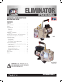 1
1
-
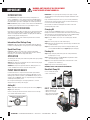 2
2
-
 3
3
-
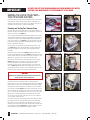 4
4
-
 5
5
-
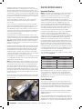 6
6
-
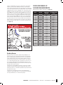 7
7
-
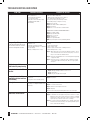 8
8
-
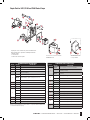 9
9
-
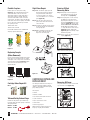 10
10
-
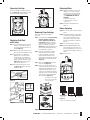 11
11
-
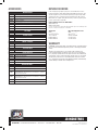 12
12
-
 13
13
-
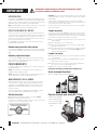 14
14
-
 15
15
-
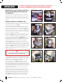 16
16
-
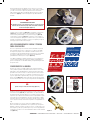 17
17
-
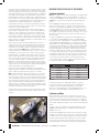 18
18
-
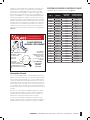 19
19
-
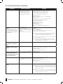 20
20
-
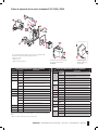 21
21
-
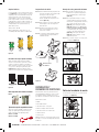 22
22
-
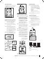 23
23
-
 24
24
-
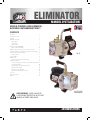 25
25
-
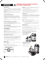 26
26
-
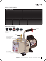 27
27
-
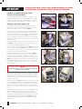 28
28
-
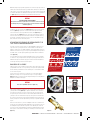 29
29
-
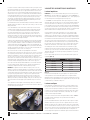 30
30
-
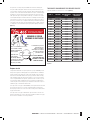 31
31
-
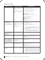 32
32
-
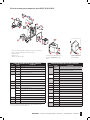 33
33
-
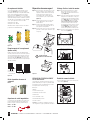 34
34
-
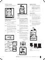 35
35
-
 36
36


JB ELIMINATOR Vacuum Pump Manuel utilisateur
- Taper
- Manuel utilisateur
- Ce manuel convient également à
dans d''autres langues
Documents connexes

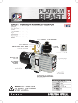

Autres documents
-
MasterCool 98063-BT Mode d'emploi
-
ClimateMaster Dedicated Outside Air Systems Le manuel du propriétaire
-
NAPOLEON WTACS0042RA1-N Manuel utilisateur
-
-
Panasonic E9RKUA Guide d'installation
-
-
-
CPS Pro-Set VP6S Mode d'emploi