Kichler Lighting 44091BK Manuel utilisateur
- Taper
- Manuel utilisateur
La page est en cours de chargement...

Date Issued: 08/14/17 IS-44091-CB
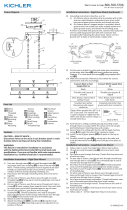
GREEN GROUND
SCREW
CUPPED
WASHER
OUTLET BOX
GROUND
FIXTURE
GROUND
DIMPLES
WIRE CONNECTOR
OUTLET BOX
GROUND
GREEN GROUND
SCREW
FIXTURE
GROUND
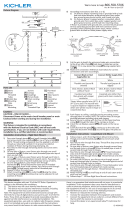
A
B
Connect Black or
Red Supply Wire to:
Connect
White Supply Wire to:
Black White
*Parallel cord (round & smooth) *Parallel cord (square & ridged)
Clear, Brown, Gold or Black
without tracer
Clear, Brown, Gold or Black
with tracer
Insulated wire (other than green)
with copper conductor
Insulated wire (other than green)
with silver conductor
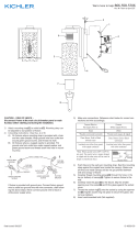
*Note: When parallel wires (SPT I & SPT II)
are used. The neutral wire is square shaped
or ridged and the other wire will be round in
shape or smooth (see illus.)
Neutral Wire
We’re here to help 866-558-5706
Hrs: M-F 9am to 5pm EST
CAUTION – RISK OF SHOCK – Disconnect Power at the main
circuit breaker panel or main fuse box before starting and dur-
ing the installation.
Before Installing: All installations should comply with National and
Local Electrician Codes. If you have any doubts concerning instal-
lation, contact a qualified licensed electrician.
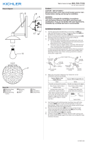
1) Find the appropriate threaded holes on mounting strap that
align with hole distance in canopy. Thread mounting screws
into threaded holes starting from outlet box side.
2) Attach mounting strap to outlet box with strap mounting
screws. Mounting strap can be adjusted to suit position of
fixture.
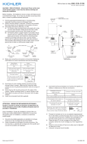
3) Grounding instructions: (See Illus. A or B)
A) On fixtures where mounting strap is provided with a
hole and two raise dimples. Wrap ground wire from
outlet box around green ground screw, and thread into
hole.
B) On fixtures where a cupped washer is provided. Put
ground wire from outlet box under cupped washer
and green ground screw and thread screw into hole in
mounting strap.
If fixture is provided with ground wire. Connect fixture
ground wire to outlet box ground wire with wire connector,
after following the above steps. Never connect ground wire
to black or white power supply wires.
4) Make wire connections. Reference chart below for correct
connections and wire accordingly.
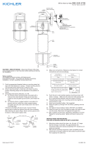
5) Push fixture to wall carefully passing mounting screws with
holes in canopy. Make sure all wires are inside canopy and
do not get pinched between wall and canopy of fixture.
6) Thread lockwasher and lockup knobs onto mounting screws
and tighten to secure fixture to wall.
7) Insert recommended bulb(s). (Not supplied)
ATTENTION – RISQUE DE DÉCHARGES ÉLECTRIQUES –
Couperle courant au niveau du panneau du disjoncteur du
circuit principal ou de la boîte à fusibles principale avant de
procéder à l’installation.
Avant l’installation: Toutes les installations doivent être con-
formes aux codes d’électricité et à l’électricité. Si vous avez
des doutes quant à l’installation, contactez un électricien
qualifié agréé.
1) Trouver les trous filetés appropriés sur la barrette de montage. Vis-
sez les vis de montage dans les trous filetés.
2) Visser la barrette de montage à la boite de jonction. (Vis
non fournies). La barrette de montage peut etre ajustée pour
convenir à la position de l’applique.
(2) STRAP MOUNTING SCREWS
VIS DE L'ÉTRIER DE MONTAGE
(2) MOUNTING SCREWS / VIS DE MONTAGE
MOUNTING STRAP / ÉTRIER DE MONTAGE
(2) LOCK-UP KNOB
BOULES DE BLOCAGE
(2) LOCKWASHERS
RONDELLE DE BLOCAGE
CANOPY / COUVERCLE
(2) SOCKETS
DOUILLE
OUTLET BOX
BOÎTE À PRISES
WIRE CONNECTORS
CONNECTEURS DE FIL
Connecter le fil noir ou
rouge de la boite
Connecter le fil blanc de la boîte
A Noir A Blanc
*Au cordon parallèle (rond et lisse)
*Au cordon parallele (à angles droits el strié)
Au bransparent, doré, marron, ou
noir sans fil distinctif
Au transparent, doré, marron, ou
noir avec un til distinctif
Fil isolé (sauf fil vert) avec
conducteur en cuivre
Fil isolé (sauf fil vert) avec
conducteur en argent
*Remarque: Avec emploi d’un fil paralléle
(SPT I et SPT II). Le fil neutre est á angles
droits ou strié et l’autre fil doit étre rond ou
lisse (Voir le schéma).
Fil Neutre
3) Connecter les fils (connecteurs non fournis). Se reporter au
tableau ci-dessous pour faire les connexions.
4) Enfoncez le luminaire sur le mur en passant soigneusement
les vis de montage avec des trous dans la verrière. Assurez-
vous que tous les fils sont à l’intérieur de la canopée et ne pas
être pincés entre le mur et la canopée de l’appareil.
5) Enfiler les boutons de verrouillage et de verrouillage sur les vis
de fixation et serrer pour fixer l’appareil au mur.
6) Installer la ou les ampoules recommandées (non fournies).
-
 1
1
-
 2
2


Kichler Lighting 44091BK Manuel utilisateur
- Taper
- Manuel utilisateur
dans d''autres langues
Documents connexes
-
 Kichler Lighting 49857BKT Manuel utilisateur
-
 Kichler Lighting 45863CH Manuel utilisateur
-
 Kichler Lighting 45929CLP Manuel utilisateur
-
 Kichler Lighting 43038DAG Manuel utilisateur
-
 Kichler Lighting 44271PN Manuel utilisateur
-
 Kichler Lighting 49980BKT Manuel utilisateur
-
Kichler 43694CH Manuel utilisateur
-
 Kichler Lighting 44340WNWLED Manuel utilisateur
-
 Kichler Lighting 44344WNWLED Manuel utilisateur
-
 Kichler Lighting 44170BK Manuel utilisateur


