GE ZDBC240NBS Guide d'installation
- Catégorie
- Cave à vin
- Taper
- Guide d'installation

INSTALLATION
INSTRUCTIONS
with Design Guide
Wine Chiller, Wine Reserve
and Beverage Center
Monogram.com

2 31-46122-6
Safety Information
BEFORE YOU BEGIN
Read these instructions completely and carefully.
•
IMPORTANT – Save these instructions for
local inspector’s use. Observe all governing codes and
ordinances.
• Note to Installer – Be sure to leave these instructions
with the Consumer.
• Note to Consumer – Keep these instructions with your
Owner’s Manual for future reference.
If you received a damaged refrigerator, you should
immediately contact your dealer or builder.
Skill Level – Installation of this refrigerator requires
basic mechanical, carpentry and plumbing skills. Proper
installation is the responsibility of the installer. Product
failure due to improper installation is not covered under
the GE Appliance Warranty. See the Owner’s Manual for
warranty information.
WARNING
Explosion Hazard. Keep flammable materials and vapors, such as gasoline, away from
refrigerator. Failure to do so can result in fire, explosion, or death.
WARNING
To reduce the risk associated with choking, do not allow children under 3 years of age to have access
to small parts during the installation of this product.
For Monogram local service in your area, call 800.444.1845 or visit monogram.com.
For Monogram service in Canada, call 888.880.3030
For Monogram Parts and Accessories, call 800.444.1845 or visit monogram.com.
For Monogram Parts and Accessories in Canada, call 888.880.3030 or visit monogram.ca.
CONNECTING ELECTRICITY
WARNING
Electrical Shock Hazard.
Plug into a grounded 3-prong outlet.
Do not remove the ground prong.
Do not use an adapter.
Do not use an extension cord.
Failure to follow these instructions can result in death, fire, or electrical shock.
Do not, under any circumstances, cut or remove the third (ground) prong from the power cord.
For personal safety, this appliance must be properly grounded.
The power cord of this appliance is equipped with a
3-prong (grounding) plug which mates with a standard
3-prong (grounding) wall outlet to minimize the possibility
of electric shock hazard from this appliance.
Have the wall outlet and circuit checked by a qualified
electrician to make sure the outlet is properly grounded.
Where a standard 2-prong wall outlet is encountered, it
is your personal responsibility and obligation to have it
replaced with a properly grounded 3-prong wall outlet. Do
not use an adapter.
The refrigerator should always be plugged into its own
individual electrical outlet which has a voltage rating that
matches the rating plate.
A 115 Volt AC, 60 Hz, 15- or 20-amp fused, grounded
electrical supply is required. This provides the best
performance and also prevents overloading house wiring
circuits which could cause a fire hazard from overheated
wires.
Never unplug your refrigerator by pulling on the power
cord. Always grip plug firmly and pull straight out from the
outlet.
Immediately discontinue use of a damaged
supply cord. If the supply cord is damaged
it must be replaced by a qualified service
professional with an authorized service part
from the manufacturer.
When moving the refrigerator away from
the wall, be careful not to roll over or
damage the power cord.

31-46122-6 3
Consignes de Sécurité
AVERTISSEMENT
Risque d’explosion.
Conservez les matériaux et vapeurs inflammables tels que l’essence à l’écart de votre réfrigérateur. Le non-respect de
cette instruction peut entraîner un risque d’incendie, d’explosion ou de décès.
AVERTISSEMENT
3RXUUpGXLUHOHULVTXHG¶pWRXႇHPHQWSHQGDQWO¶LQVWDOODWLRQGHFHSURGXLWQHSDVODLVVHUOHV
petites pièces à la portée des enfants âgés de moins de 3 ans.
AVERTISSEMENT
Risque d’électrocution.
Branchez l’appareil dans une prise à 3 broches mise à la terre.
N’enlevez pas la broche de mise à la terre.
N’utilisez pas un adaptateur.
N’utilisez pas un cordon de rallonge.
Le non-respect de ces instructions peut entraîner des risques d’incendies, des chocs électriques ou la mort.
BRANCHEMENTS ÉLECTRIQUES
Ne coupez pas ou n’enlevez pas, sous aucun prétexte, la troisième broche de mise à la terre du cordon
d’alimentation. Pour des raisons de sécurité, cet appareil doit être correctement mis à la terre.
Le cordon d’alimentation de cet appareil est équipé d’une
fiche à trois broches (pour une mise à la terre) qui s’adapte
à la prise de courant standard à 3 broches (pour une mise
à la terre) pour minimiser les risques de chocs électriques
par cet appareil.
Faites vérifier la prise murale et le circuit électrique par
un électricien qualifié pour s’assurer que le système est
correctement mis à la terre.
Dans le cas d’une prise biphasée, l’installateur a la
responsabilité et l’obligation de la remplacer par une prise
triphasée correctement mise à la terre. N’utilisez pas
d’adaptateur.
Le réfrigérateur doit toujours être branché à sa propre
prise électrique d’une tension nominale correspondant à
celle indiquée sur sa plaque signalétique.
Une alimentation électrique à 115 volts CA, 60 Hz, avec
un fusible de 15 ou 20 ampères et une mise à la terre est
nécessaire. Ceci permet d’obtenir un meilleur rendement
et évite de surcharger les circuits électriques du domicile
qui risque d’occasionner un incendie en surchauffant.
Ne débranchez jamais le réfrigérateur en tirant sur le
cordon d’alimentation. Prenez toujours fermement la fiche
en main et tirez pour la sortir de la prise.
Cessez immédiatement l’utilisation d’un
cordon électrique endommagé. Si le
cordon électrique est endommagé, son
remplacement doit être exécuté par un
technicien en réparation qualifié au moyen
d’un cordon de rechange autorisé par le
fabricant.
Lorsque vous éloignez votre réfrigérateur
du mur, faites attention à ne pas le faire
rouler sur le cordon d’alimentation afin de
ne pas l’endommager.

4 31-46122-6
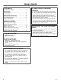
CONTENTS
Important Information .............................................2, 3
Design Guide
Tools Required ..............................................................4
Parts Supplied ...............................................................4
Staining Wood Drawer Fronts ......................................4
Installing Custom Frame Panel ....................................4
The Installation Space ............................................. 5
Product Clearances ................................................. 6
Side-by-Side Installation ......................................... 6
Installation Instructions
Step 1, Remove Packaging ..................................... 7
Step 2, Reverse Door Swing ................................... 7
Step 3, Leveling ....................................................... 8
Step 4, Connect Power............................................ 8
Step 5, Slide Product into Cutout ............................ 8
Step 6, Set Temperature Controls ........................... 8
Custom Frame Panel Models .................................. 9
Design Guide
TOOLS REQUIRED
• #2 Phillips screwdriver
• Adjustable wrench
PARTS SUPPLIED
• Hardware for changing door swing
• Optional stainless steel toekick with screws and
spacers
• Left and right side hinge covers
• Top screw hole cover
STAINING WOOD DRAWER
FRONTS
7KHGUDZHUIURQWVDUHXQ¿QLVKHGFKHUU\ZRRG'XULQJ
use, oil from hands may accumulate and stain the wood.
• The drawer fronts may be stained and sealed to match
adjacent cabinetry. The tinted glass will make the
stained wood appear darker. A true color match can be
seen only when the door is opened.
• Apply the stain and sealer according to the manufac-
turer’s instructions. To avoid unpleasant odor, keep the
door open to ventilate and allow the stain/sealer to dry
completely before using the product.
INSTALLING THE CUSTOM FRAME
PANEL
Go to page 6 for custom frame panel size, depending on
your cabinet size and style.
• Install a custom handle of your choice onto the custom
panel before the panel is secured to the door.
• The custom panel should be installed before sliding the
product into the installation location.
REFRIGERATOR LOCATION
• Do not install the refrigerator where the temperature
will go below 55°F (12.7°C) because it will not run
often enough to maintain proper temperatures.
• Do not install the refrigerator where the tempera-
ture will go above 100°F (37°C) because it will not
perform properly.
• Do not install the refrigerator in a location exposed to
water (rain, etc.) or direct sunlight.
• Install it on a floor strong enough to support it fully
loaded.

31-46122-6 5
Design Guide
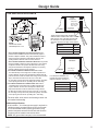
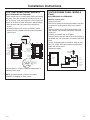
THE INSTALLATION SPACE
*For a standard installation of Custom-Framed unit: The
product must be installed so that the front face will project 2"
forward of adjacent cabinets. This position will allow a full door
swing and prevent interference with adjacent cabinetry. The
opening between cabinets must be 23-3/4" minimum.
*For a standard installation of Stainless Steel unit: The product
must be installed so that the front face will project 1-3/4" forward
of adjacent cabinets. This position will allow a full door swing
and prevent interference with adjacent cabinetry. The opening
between cabinets must be 23-3/4" minimum.
)RUDÀXVKLQVWDOODWLRQRI6WDLQOHVV6WHHOXQLW Install a
ZLGH¿OOHUVWULSRQWKHKLQJHVLGH7KH¿OOHUVWULSZLOODFWDV
a spacer between the door case and adjacent cabinets and will
SUHYHQWLQWHUIHUHQFHZLWKWKHFDELQHWGRRUVZLQJ5HFHVVWKH¿OOHU
strip 2" back from the front face of the unit, or even with
the front edge of the product case (behind the gasket). The width
RIWKHRSHQLQJPXVWEHLQFOXGLQJWKH¿OOHUVWULS
)RUDÀXVKLQVWDOODWLRQRI&XVWRP)UDPHGXQLW Install a
ZLGH¿OOHUVWULSRQWKHKLQJHVLGH7KH¿OOHUVWULSZLOODFWDV
a spacer between the door case and adjacent cabinets and
will prevent interference with the cabinet door swing. Recess
WKH¿OOHUVWULSEDFNIURPWKHIURQWIDFHRIWKHXQLWRUHYHQZLWK
the front edge of the product case (behind the gasket). The width
RIWKHRSHQLQJPXVWEHLQFOXGLQJWKH¿OOHUVWULS
• The wine chiller, wine reserve and beverage center can
be installed freestanding.
$GGLWLRQDO6SHFL¿FDWLRQV
• A 120 volt 60Hz., 15 or 20 amp power supply is required. An
individual properly grounded branch circuit or circuit break-
er is recommended. Install a properly grounded 3-prong
electrical receptacle recessed into the back wall as shown.
Electrical must be located on rear wall as shown.
NOTE: GFI (ground fault interrupter) is not recommended.
NOTE:
Handle and handle
VWDQGRႇGHSWKLV
7KHVHSURGXFWVZLOO¿WÀXVKWRDGMDFHQW
cabinets when installed with a Dim. A-width
¿OOHUSDQHORUFOHDW7KH¿OOHUSDQHOVKRXOG
be recessed or set back behind the door
and even with the front edge of the product
case.
Product Dim. A
ZDWI240, ZDBI240 1"
ZDWC240, ZDWR240 1/2"
ZDBC240, ZDBR240 1/2"
In a standard installation, the
product will project forward of
adjacent cabinets. See Dim. A.
Flush
Installation
CABINET
CABINET
CABINET
CABINET
Dim. A
Dim. A
120°
120°
110°
110°
Filler panel or
cleat to be set
back even with
front of case.
Front edge of
product case
Front face
Front face
Front edge of
product case
Standard
Installation
Product Dim. A
ZDWI240, ZDBI240 2"
ZDWC240, ZDWR240 1-3/4"
ZDBC240, ZDBR240 1-3/4"

6 31-46122-6
Design Guide
SIDE-BY-SIDE INSTALLATIONS
Increase storage capacity by installing two Monogram
beverage centers, wine chillers or wine reserves
together. Or, for a complete refreshment center, install
any two of these units together.
• A side-by-side installation requires at least a 47-1/2"-
wide minimum opening for standard installation and
DZLGHPLQLPXPRSHQLQJIRUÀXVKLQVWDOODWLRQ
of stainless steel models. A 49-1/2"-wide minimum
RSHQLQJLVUHTXLUHGIRUVLGHE\VLGHÀXVKLQVWDOODWLRQ
of custom framed models.
• Products must operate from separate, properly
grounded receptacles.
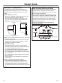
PRODUCT CLEARANCES
The stainless steel wine chiller, wine reserve and
beverage center is factory set for a 110° door swing.
Models that accept custom panels have a 95° door
swing.
When installed in a corner:
• Allow 4" min. clearance on the hinge side for the 90°
door swing and to allow racks to slide out.
• Allow 10" minimum clearance on the hinge side for
a full 110° door swing. (Models ZDWI240WII and
ZDBI240WII have a 95° door swing.)
NOTE: Custom handle clearances may vary, depending
on custom handle depth.
• The door swing is reversible on all models. If desired,
change the door swing before installation or before
installing the custom frame panel.
Choose the location:
• These products may be closed in on the top and
three sides as long as the front is unobstructed for air
circulation and proper access to the door.
• Do not install these products where the temperature
will go below 55°F (13°C) or above 100°F (37°C).
• Do not install where it will be subject to direct sunlight,
heat or moisture.
• Do not install where it will be subject to direct sunlight,
heat or moisture.
• These products are not designed to be stacked one
over the other.
Black or Stainless Steel Toekick Options
• These products are shipped with a black toekick
installed. An optional stainless steel toekick is also
supplied with each product. For shipping purposes,
the stainless steel toekick is secured to the back of the
unit.
90° Door Swing
10" Minimum
to Wall
110*
*95 Door Swing on Custom Frame Models
21-5/8"
23-5/8"
4" Minimum
to Wall
90

31-46122-6 7
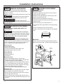
STEP 2 REVERSE DOOR SWING
(Cont.)
Reinstall the door:
• Install the original door stop and cam riser onto the
bottom left side of the door.
• Install the new supplied bottom case hinge pin and
bracket onto bottom left side.
• Place the door onto the bottom case hinge.
• Install the supplied left-hand top case hinge with the 3
original screws.
• Select the hinge cover marked with an “L”.
3HHOEDFNLQJRႇWKHWDSHLQVLGHWKHGHFRUDWLYHKLQJH
cover.
• Press and snap the hinge cover into place.
• Snap the screw hole cover into place on the opposite
side.
IMPORTANT:
Check to be sure screws are tight and that the door is
straight and does not sag. The door should swing freely.
Installation Instructions
Install Covers
Remove
Top Hinge
Remove
Hinge
Install
3 Hinge
Screws
Door Stop
and Cam Riser
Hinge
Pin and
Bracket
STEP 1 REMOVE PACKAGING
• Remove corner blocks and foam drawer stops.
• Remove all packing material, tape and protective
plastic coverings.
• Remove stainless steel toekick taped to the back of the
unit.
WARNING
Small objects are a choke hazard for
children. Remove and discard any parts not used.
AVERTISSEMENT
Les petits objets peuvent
étrangler les enfants. Il faut jeter toutes les pièces qui ne
sont pas utilisées.
STEP 2 REVERSE DOOR SWING
SKIP THIS STEP IF DOOR SWING SUITS THE
INSTALLATION
WARNING
Follow all steps when reversing the
door swing. Failure to follow these instructions, leaving
off parts, or overtightening screws, can lead to the door
falling off and result in injury and property damage.
AVERTISSEMENT
Suivez toutes les étapes lors du
changement d’ouverture de la porte. La porte risque de
tomber en plus de causer des blessures ou des dommages
si vous ne respectez pas ces instructions, oubliez des
SLqFHVRXHႇHFWXH]XQVHUUDJHH[FHVVLIGHVYLV
Parts Included:
• Top left case hinge
• Bottom left case hinge
• Left and right side decorative hinge cover
• Decorative hinge screw hole cover
• Torx
®
driver bit
Tools Required:
• Phillips screwdriver
• Electric drill
Remove the door:
• Flatten the shipping carton to use as a pad.
• Remove the 2 screws and the toekick. Set aside the
VFUHZVDQGWRHNLFNIRU¿QDOLQVWDOODWLRQ
• Use the supplied Torx
®
bit and electric drill to remove
WKHVFUHZVKROGLQJWKHWRSFDVHKLQJH/LIWRႇWKH
hinge. (Screws will be used to install the new hinge.)
/LIWWKHGRRURႇWKHERWWRPFDVHKLQJH
• Remove the bottom case hinge pin and bracket.
Rotate the door:
The handle will be on the right side of the door; hinges
will be installed on the left side of the case.
• Remove the door stop and cam riser on the original
bottom right side of the door.
5HPRYHWKH¿OOSOXJRQWKHWRSULJKWVLGHRIWKHGRRU
7XUQWKHGRRURYHUDQGUHLQVWDOOWKH¿OOSOXJRQWKHQHZ
left side.

8 31-46122-6
Turn Right to Lower
Turn Left to Raise
Installation Instructions
STEP 3 LEVEL
• Use an adjustable wrench to turn the leveling legs and
raise or lower the product.
• Adjust carefully; the product should be level and plumb
with cabinetry, and should align with adjacent toekick
height.
If you skipped Step 2:
• Select the hinge cover marked “R” or “L”, depending on
door swing.
3HHOEDFNLQJRႇWKHWDSHLQVLGHWKHGHFRUDWLYHKLQJH
cover. Press and snap into position.
• Snap the screw hole cover into place on the opposite
side.
STEP 4 CONNECT POWER
• Connect power cord plug to a properly grounded re-
ceptacle.
• Check to make sure power is on by opening the door
to see if interior light turns on.
STEP 6 SET TEMPERATURE
CONTROLS
• The temperature controls are preset. Refer to the
Owner’s Manual for more information. Allow 24 hours
for temperature to stabilize.
STEP 5 SLIDE PRODUCT INTO THE
CUTOUT
• Carefully, slide the unit into the opening. Be careful not
to entangle the power cord.
0DNHFHUWDLQWKDWWKHGRRUSURWUXGHVƎEH\RQGWKH
VXUURXQGLQJFDELQHWVƎIRUFXVWRPIUDPHPRGHOV
• Check again to be sure the unit is level.
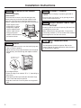
STEP 2 REVERSE DOOR SWING
(Cont.)
Install Toekick
The toekick has a cutout on the left and right sides.
Remove the plug on the left side and reinstall on the
right side. If you choose to install the stainless steel
toekick, reinstall the plug on the right side of that toekick.
• Install original screws
and spacers or screws
and spacers supplied
with the stainless steel
toekick. Install screws
through the spacer
VWDQGRႇWRHNLFNDQGLQWR
the base as shown.

31-46122-6 9
CUSTOM FRAME PANEL MODELS
Model ZDWI240WII and ZDBI240WII
These models require a custom panel frame surrounding
the glass. There are two options: the panel may be 29-
ƎRUƎKLJK$ƎSDQHOUHTXLUHVDQRWFKFXWLQWRWKH
bottom of the panel to avoid interference with the hinges.
• Rout the back side of the panel to the dimensions
shown.
• A custom handle of your choice or ZTBSS1 Tubular
Handle must be installed before the panel is mounted
onto the door.
NOTE: A solid panel that covers the door glass
CANNOT be installed on these models.
CUSTOM FRAME PANEL MODELS
(Cont.)
Model ZDWI240WII and ZDBI240WII
Install the custom panel:
• Open the door fully.
• Remove the gasket surrounding the inside of the door
to expose the existing screw holes for the custom
panel.
• Hold the custom frame panel against the door and
align carefully, top to bottom and side to side. Mark
screw hole
locations on the back side of the panel.
• Drill pilot holes in the back side of the custom panel. In
KDUGZRRGGULOOƎSLORWKROHV,QVRIWZRRGGULOOƎ
holes.
• Secure the prepared panel to the door using ten (10)
[ƎVFUHZV'ULYHWKHVFUHZVWKURXJKWKHGRRU
frame and into the wood.
• Replace the gasket.
Installation Instructions
#8 x 5/8"
Screws
GLASS
Back
Custom
Framed
Panel
Door
Frame
23-1/8”
30”
GLASS
25-1/4”
18-5/8”
2-1/4”
Rout the back
side of the
opening 7/16”
deep, 1-1/8” wide
Cut the notch
1/8” deep, 1/4”
wide and 1/4”
high
2-1/4”
1/8”
1/4”
1/4”
2-1/4”
2-1/2” at
bottom
23-1/8”
29-3/4”
GLASS
25-1/4”
3/4” Thick Custom Panel,
Back Side
18-5/8”
2-1/4”
wide,
all sides
Rout the
back side
of the
opening
7/16”deep,
1-1/8” wide
Choose Option 1 or Option 2 panel size depending on
cabinetry size or style.

10 31-46122-6
Notes

31-46122-6 11
Notes

NOTE: While performing installations described in this
book, safety glasses or goggles should be worn.
NOTE: Product improvement is a continuing endeavor
at Monogram. Therefore, materials, appearance and
specifications are subject to change without notice.
31-46122-6
02-19 GEA
Monogram.com
Printed in Serbia
-
 1
1
-
 2
2
-
 3
3
-
 4
4
-
 5
5
-
 6
6
-
 7
7
-
 8
8
-
 9
9
-
 10
10
-
 11
11
-
 12
12


GE ZDBC240NBS Guide d'installation
- Catégorie
- Cave à vin
- Taper
- Guide d'installation
dans d''autres langues
- English: GE ZDBC240NBS Installation guide
