ABB PVI-3.0-OUTD-S-US Manuel utilisateur
- Taper
- Manuel utilisateur


The purpose of this document is to support the quali¿ed technician, who has received training
and/or has demonstrated skills and knowledge in construction, to install and maintain this inverter.
NOTE: Any changes or modi¿cations not approved by the responsible party could void the
device, pursuant to Part 15 of the FCC Rules. These limits are designed to provide reasonable
protection against harmful interference in a residential installation. This equipment generates,
uses and can radiate radio frequency energy and, if not installed and used in accordance with
the instructions, may cause harmful interference to radio communications.
However, there is no guarantee that interference will not occur in a particular installation. If
this equipment does cause harmful interference to radio or television reception, which can be
determined by turning the equipment off and on, the user is encouraged to try to correct the
• Reorient or relocate the receiving antenna.
•
•
•


I
ntroduction and safety ...................................................................................................................... 7
I
nstallation location ..........................................................................................................................13
M
ounting and wiring ....................................................................................................................... 17

O
perations ........................................................................................................................................ 33
T
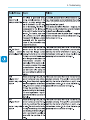
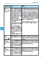
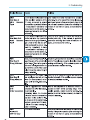
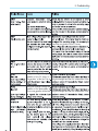
roubleshooting ............................................................................................................................... 49
M
aintenance ..................................................................................................................................... 63
A
ppendix ........................................................................................................................................... 67

Introduction and safety

1- Introduction and safety
by quali¿ed, trained personnel and in compliance with all prevailing local codes and regula
installation location and adhere to speci¿ed cooling requirements.
quali¿ed technical personnel.
WARNING: To reduce the risk of ¿re, connect only to a circuit provided with 15A,

1- Introduction and safety
These servicing instructions are for use by quali¿ed personnel only. To reduce the risk of electric shock, do not
perform any servicing other than that speci¿ed in the operating instructions. Be sure all Àammable materials
immediately following shut down, surface temperatures on the cooling ¿ns (heat
areas or operations: magnetic ¿elds, hazardous voltages, high temperatures, possibility of
as some components can retain charge suf¿cient to create a shock hazard and may need

1- Introduction and safety
Note the location of safety notices on the inverter for noti¿cation and protection. Labels must
indoors if installed to speci¿ed environmental and mounting parameters stated in this manual, and adherence
ed array(s) to be Àoating with respect to ground; it can be used only with photovol
•
technical speci¿cations.
• The inverter is certi¿ed for use only with photovoltaic arrays connected to its input
•

1- Introduction and safety
• Installing the equipment in environments with Àammable conditions.
•
•
•
•
•
• Blocking airÀow to the cooling ¿ns (e.g., warming or drying rags) on the unit or accessory

1- Introduction and safety
•
•
labels af¿xed to the equipment.
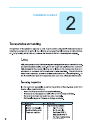
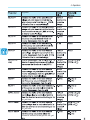
The nameplate shown is af¿xed
5. Certi¿cation
UL 1741
CSA-C22.2 No. 107.1-01
C US
®
Country of Origin Italy
www.abb.com/solar
SOLAR UTILITY INTERACTIVE
TRANSFORMERLESS INVERTER
MODEL:PVI-3.0-OUTD-S-US
This device complies with Part 15 of the FCC Rules. Operation is subject to the
f
o
l
l
o
w
i
n
g
t
w
o
Nominal Input Operating Voltage
Max. Input Voltage
Range of Input Operating Voltage
Range of Input Voltage @Full Power
Max. Input Current
Max.Input Short Circuit Current (P.V.Panels)
DC RATING
Nominal Output Voltage
Operating Voltage Range
Nominal Output Frequency
Operating Frequency Range
Output Power Factor
Max.Output Current
AC RATING
Max. Continuous Output Power
Max. Output Overcurrent Protection
2 x 10 A
2 x 12.5 A
360 V
600 V
90 - 580 V
200 - 530 V
60 Hz (factory preset)
59.3 ( ) - 60.5 ( ) Hz
1 2
>0.995
12 A / 14.5A / 14.5 A (rms)
277 V~ / 240 V~ / 208 V~ 1Ø
15 A / 20A / 20 A
3000 W @ 55°C amb.
244-304 V~/211-264 V~/183-228 V~
DC Ground Fault Detector/Interrupter is Provided
Operating Ambient Temperature:-25 to +60 °C(-13 to +140 °F), with Output Power Derating
Type of Enclosure:NEMA 4X
For more details about product speci cations refer to the Instruction Manual
(1):
2
Adjustable from 57.0 Hz to 59.8 Hz
Adjustable from 60.2 Hz to 63.0 Hz
( ):
c
o
n
d
i
t
i
o
n
s
:
(
1
)
t
h
i
s
d
e
v
i
c
e
m
a
y
n
o
t
c
a
u
s
e
h
a
r
m
f
u
l
i
n
t
e
r
f
e
r
e
n
c
e
,
a
n
d
1
2
3
4
5
7
8
6

•
•
•
•
5
6
m
m
À
a
t
w
a
s
h
e
r
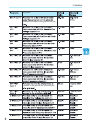
Installation location

2 - Installation location
The inverter must be installed by quali¿ed installers and/or licensed electricians
•
•
• Installing the inverter where operating temperatures exceed the speci¿cations will
result in power limiting. It is recommended the inverter be installed within the speci¿ed
•
•
•
• To avoid overheating, always make sure the Àow of air around the inverter is not blocked.
• Do not install in places where gases or Àammable substances may be present.
Air ow restricted use caution

2 - Installation location
•
•
•
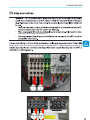
• Ensure suf¿cient working area in front of the inverter to allow removal of the covers and
•
6
in
8
in
6 in 6 in
UNO
25” 25”
25”

2 - Installation location

- 6mm Àat washer
Mounting and wiring

3 - Mounting and wiring
•
•
•
•
•
•
•
•
through bottom Àange securing to
188mm

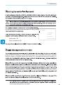
3 - Mounting and wiring
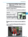
: Always respect the nominal ratings of voltage and current de¿ned in the
•
•
Table 3-1 switchbox external components
sets of switch contacts to guarantee the switch current speci¿cations are not exceeded.

3 - Mounting and wiring
DC electrical schematics for front switchbox, AFD available on –A models only
•
•
•
La page charge ...
La page charge ...
La page charge ...
La page charge ...
La page charge ...
La page charge ...
La page charge ...
La page charge ...
La page charge ...
La page charge ...
La page charge ...
La page charge ...
La page charge ...
La page charge ...
La page charge ...
La page charge ...
La page charge ...
La page charge ...
La page charge ...
La page charge ...
La page charge ...
La page charge ...
La page charge ...
La page charge ...
La page charge ...
La page charge ...
La page charge ...
La page charge ...
La page charge ...
La page charge ...
La page charge ...
La page charge ...
La page charge ...
La page charge ...
La page charge ...
La page charge ...
La page charge ...
La page charge ...
La page charge ...
La page charge ...
La page charge ...
La page charge ...
La page charge ...
La page charge ...
La page charge ...
La page charge ...
La page charge ...
La page charge ...
La page charge ...
La page charge ...
La page charge ...
La page charge ...
La page charge ...
La page charge ...
La page charge ...
-
 1
1
-
 2
2
-
 3
3
-
 4
4
-
 5
5
-
 6
6
-
 7
7
-
 8
8
-
 9
9
-
 10
10
-
 11
11
-
 12
12
-
 13
13
-
 14
14
-
 15
15
-
 16
16
-
 17
17
-
 18
18
-
 19
19
-
 20
20
-
 21
21
-
 22
22
-
 23
23
-
 24
24
-
 25
25
-
 26
26
-
 27
27
-
 28
28
-
 29
29
-
 30
30
-
 31
31
-
 32
32
-
 33
33
-
 34
34
-
 35
35
-
 36
36
-
 37
37
-
 38
38
-
 39
39
-
 40
40
-
 41
41
-
 42
42
-
 43
43
-
 44
44
-
 45
45
-
 46
46
-
 47
47
-
 48
48
-
 49
49
-
 50
50
-
 51
51
-
 52
52
-
 53
53
-
 54
54
-
 55
55
-
 56
56
-
 57
57
-
 58
58
-
 59
59
-
 60
60
-
 61
61
-
 62
62
-
 63
63
-
 64
64
-
 65
65
-
 66
66
-
 67
67
-
 68
68
-
 69
69
-
 70
70
-
 71
71
-
 72
72
-
 73
73
-
 74
74
-
 75
75


ABB PVI-3.0-OUTD-S-US Manuel utilisateur
- Taper
- Manuel utilisateur
dans d''autres langues
- English: ABB PVI-3.0-OUTD-S-US User manual
Autres documents
-
 Fronius 24.0-3 480 Symo Advanced Le manuel du propriétaire
-
Fujitsu AOYA72LALT Guide d'installation
-
Fujitsu AOTA90LALT Guide d'installation
-
-
Fujitsu AOU48RLXFZ1 Guide d'installation
-
-
Acard AEC-6896 Guide d'installation
-
-
Fujitsu AUGA36FRTA Guide d'installation
-
Hitachi J300 series Power Up Instructions
