Fronius 24.0-3 480 Symo Advanced Le manuel du propriétaire
- Taper
- Le manuel du propriétaire

Operating
Instructions
Fronius Symo Advanced
10.0-3 208-240
12.0-3 208-240
15.0-3 480
20.0-3 480
22.7-3 480
24.0-3 480
42,0410,0192 024-27122022
EN-US Operating instructions
FR Instructions de service
ES Manual de instrucciones


Table of contents
Safety rules 5
Explanation of safety instructions 5
General 5
Environmental conditions 6
Qualified personnel 6
Data Regarding Noise Emission Values 6
EMC measures 6
Safety symbols 7
Disposal 7
Data backup 7
Copyright 7
General 8
Device concept 8
Software version 8
Intended Use 9
Information on ‘Field-adjustable trip points’ and ‘Advanced Grid Features’ 9
FCC / RSS Compliance 9
Insulation Monitor/Interruption, Insulation Monitoring 10
Arc detection/interruption 10
Power Line Communication (PLC) transmitter 11
Warning notices on the device 11
String fuses 12
Criteria for the Proper Selection of String Fuses 13
Data Communication and Fronius Solar Net 14
Fronius Solar Net and data interface 14
Data Communication Area 14
Explanation of Multifunctional Power Interface 15
'Fronius Solar Net' LED description 16
Example 17
Fronius Datamanager 2.0 18
Controls, Connections, and Indicators on the Fronius Datamanager 2.0 18
Fronius Datamanager at night or when insufficient DC voltage is available 21
Safety 21
Installing Inverters with Fronius Datamanager 2.0 in Fronius Solar Net 21
Starting for the first time 22
More Detailed Information on Fronius Datamanager 2.0 24
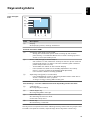
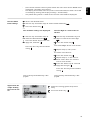
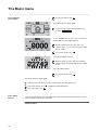
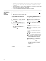
Keys and symbols 25
Keys and Symbols 25
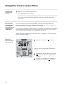
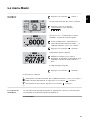
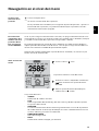
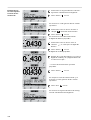
Display 26
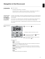
Navigation in the Menu Level 27
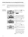
Activate the display illumination 27
Automatic Deactivation of Display Illumination / Switching to the "NOW" Display Mode 27
Access the menu level 27
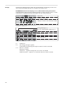
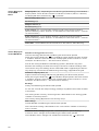
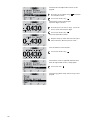
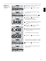
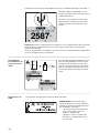
Values Displayed in the NOW Menu 28
Values Displayed in the LOG Menu 28
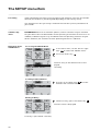
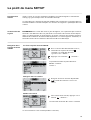
The SETUP menu item 30
Presetting 30
Software Updates 30
Navigation in the SETUP Menu 30
General Menu Item Settings 31
Application Example: Setting the Feed-In Tariff 31
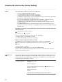
Menu Items in the Setup Menu 33
Standby 33
WLAN Access Point 33
DATCOM 34
USB 34
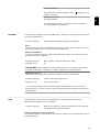
Relay (Floating Switch Contact) 36
Energy Manager(in the Relay Menu) 37
Time/Date 38
Display Settings 39
3
EN-US

Energy yield 40
Fan 41
Arc Detection 41
The INFO menu item 42
Measured values 42
LT Status 42
Grid Status 42
Device information 42
Version 44
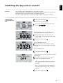
Switching the key lock on and off 45
General 45
Switching the Key Lock On and Off 45
USB Stick as a Data Logger and for Updating Inverter Software 46
USB Thumb Drive as a Data Logger 46
Suitable USB Thumb Drives 46
USB thumb drive for updating inverter software 47
Removing the USB Stick 47
The Basic menu 48
Accessing the Basic Menu 48
Basic Menu Entries 48
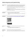
Status Diagnosis and Troubleshooting 50
Displaying status codes 50
Total Failure of the Display 50
Status codes in the eManual 50
Customer service 50
Operation in dusty environments 50
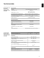
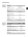
Technical data 51
General data and protection devices 10.0-3 208-240 / 24.0-3 208-240 51
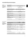
Technical data Fronius Symo Advanced 10.0-3 208-240 / 12.0-3 208-240 51
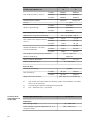
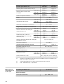
Technical data Symo Advanced 15.0-3 480 52
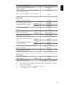
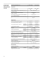
Technical data Fronius Symo Advanced 20.0-3 208-240 - 22.7-3 208-240 54
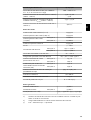
Technical data Fronius Symo Advanced 24.0-3 208-240 55
Relevant standards and directives 56
RCMU 56
Terms and conditions of warranty and disposal 57
Fronius manufacturer's warranty 57
Disposal 57
4

Safety rules
Explanation of
safety instruc-
tions
WARNING!
Indicates a potentially dangerous situation.
▶Death or serious injury may result if appropriate precautions are not taken.
CAUTION!
Indicates a potentially harmful situation.
▶Minor injury or damage to property may result if appropriate precautions are
not taken.
NOTE!
Indicates a possibility of flawed work results and possible damage to the equip-
ment.
Please pay special attention when one of the symbols from the "Safety rules"
chapter appears in these instructions.
General The device has been manufactured using state-of-the-art technology and ac-
cording to recognized safety standards. If used incorrectly or misused, however,
it can cause
-serious or fatal injury to the operator or a third party,
-and damage to the device and other material assets belonging to the operat-
ing company.
All persons involved in start-up operation, maintenance and servicing of the
device must
-be suitably qualified,
-have knowledge of and experience in dealing with electrical installations and
-have fully read and precisely followed these Operating Instructions.
The Operating Instructions must always be kept on hand wherever the device is
being used. In addition to the Operating Instructions, all applicable local rules
and regulations regarding accident prevention and environmental protection
must also be followed.
All safety and danger notices on the device
-must be kept in a legible state
-must not be damaged/marked
-must not be removed
-must not be covered, pasted, or painted over.
The terminals can reach high temperatures.
Only operate the device when all protection devices are fully functional. If the
protection devices are not fully functional, there is a risk of
-serious or fatal injury to the operator or a third party,
-and damage to the device and other material assets belonging to the operat-
ing company.
Any safety devices that are not functioning properly must be repaired by an au-
thorized specialist before the device is switched on.
5
EN-US

Never bypass or disable protection devices.
For the location of the safety and danger notices on the device, refer to the sec-
tion headed “General” in the Operating Instructions for the device.
Any equipment malfunctions which might impair safety must be remedied imme-
diately before the device is turned on.
Your personal safety is at stake!
Environmental
conditions
Operation or storage of the device outside the stipulated area will be deemed as
not in accordance with the intended purpose. The manufacturer accepts no liab-
ility for any damage resulting from improper use.
Qualified per-
sonnel
The servicing information contained in these Operating Instructions is intended
only for the use of qualified service engineers. An electric shock can be fatal. Do
not carry out any actions other than those described in the documentation. This
also applies to qualified personnel.
All cables and leads must be secured, undamaged, insulated, and adequately di-
mensioned. Loose connections, scorched, damaged, or under-dimensioned
cables and leads must be repaired immediately by an authorized specialist.
Maintenance and repair work must only be carried out by an authorized special-
ist.
It is impossible to guarantee that externally (aka, third-party) procured parts are
designed and manufactured to meet the demands made on them, or that they
satisfy safety requirements. Use only original spare parts (also applies to stand-
ard parts).
Do not carry out any alterations, installations, or modifications to the device
without first obtaining the manufacturer's permission.
Components that are not in perfect condition must be changed immediately.
Data Regarding
Noise Emission
Values
The cooling of the device takes place via an electronic temperature
control system at the lowest possible noise level and depends on the
power used, ambient temperature and the soiling level of the device,
etc.
It is not possible to provide a workplace-related emission value for
this device, because the actual sound pressure level is heavily influ-
enced by the installation situation, the power quality, the surround-
ing walls and the properties of the room in general.
EMC measures In certain cases, even though a device complies with the standard limit values for
emissions, it may affect the application area for which it was designed (e.g., when
there is sensitive equipment at the same location, or if the site where the device
is installed is close to either radio or television receivers). If this is the case, then
the operator is obliged to take appropriate action to rectify the situation.
6

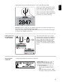
Safety symbols Devices marked with the CSA test mark satisfy the requirements of the relevant
standards for Canada and the USA.
Disposal Dispose of in accordance with the applicable national and local regulations.
Data backup The user is responsible for backing up any changes made to the factory settings.
The manufacturer accepts no liability for any deleted personal settings.
Copyright Copyright of these Operating Instructions remains with the manufacturer.
Text and illustrations were accurate at the time of printing. Fronius reserves the
right to make changes. The contents of the Operating Instructions shall not
provide the basis for any claims whatsoever on the part of the purchaser. If you
have any suggestions for improvement, or can point out any mistakes that you
have found in the Operating Instructions, we will be most grateful for your com-
ments.
7
EN-US

General
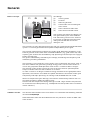
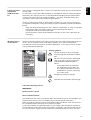
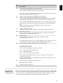
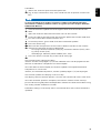
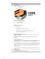
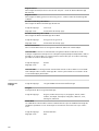
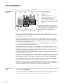
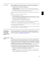
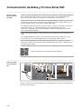
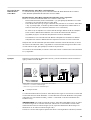
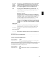
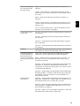
Device concept Unit design:
(1) Housing cover
(2) Inverter
(3) Mounting bracket
(4) Connection area including DC
main switch
(5) Data Communication Area
(6) Data communication cover
The inverter transforms the direct cur-
rent generated by the solar modules
into alternating current. This alternat-
ing current is fed into the public grid
and synchronized with the mains
voltage in use.
The inverter has been designed exclusively for use in grid-connected photovoltaic
systems. It cannot generate electric power independently of the grid.
The inverter automatically monitors the public grid. Whenever conditions in the
electric grid are inconsistent with standard conditions (e.g., grid switch-off, inter-
ruption), your inverter will immediately stop operating and interrupt the supply of
power into the grid.
The grid is monitored by monitoring the voltage, monitoring the frequency and
monitoring islanding conditions.
The inverter is fully automatic. The inverter starts monitoring the grid as soon as
the solar modules are generating enough energy after sunrise. The inverter re-
sumes the grid power feed operation when there is sufficient direct sunlight.
The control system of the inverter ensures that the maximum possible power
output is drawn from the solar modules at all times.
As soon as there is no longer sufficient energy available for the grid power feed
operation, the inverter shuts down the power electronics connection to the grid
completely and stops operating. All settings and recorded data are saved.
When its temperature gets too high, the inverter automatically reduces the cur-
rent output power in order to protect itself.
Reasons for the temperature being too high include a high ambient temperature
or insufficient heat dissipation (e.g., inadequate heat dissipation when installed in
switch cabinets).
Software version The features described in these instructions are valid from the following software
version: fro28500.upd
Minor deviations from the described features are possible in newer or older soft-
ware versions.
8

Intended Use The inverter is designed exclusively to convert direct current from solar modules
into alternating current and feed this power into the public grid.
The following are deemed to be not in conformity with its intended purpose:
-Utilization for any other purpose, or in any other manner
-Alternations to the inverter are not expressly recommended by Fronius
-Installation of components that are not expressly recommended or sold by
Fronius.
The manufacturer is not responsible for any damage resulting from improper use.
All warranty claims are considered void in such cases.
Proper use also means
-carefully reading and obeying the instructions and all the safety and danger
notices in the Operating and Installation Instructions
-compliance with the maintenance operations
-installation as specified in the Installation Instructions
When configuring the photovoltaic system, make sure that all components are
operating completely within their permitted operating range.
All measures recommended by the solar module manufacturer for maintaining
solar module properties must be followed.
Follow all grid operator regulations regarding grid power feed and connection
methods.
Information on
‘Field-adjustable
trip points’ and
‘Advanced Grid
Features’
The inverter is equipped with ‘Field adjustable trip points’ and ‘Advanced Grid
Features’. For further information, please contact ‘Fronius Technical Support’ at
the following email address: pv-support-usa@fronius.com.
FCC / RSS Com-
pliance
FCC
This device corresponds to the limit values for a digital device of class B in ac-
cordance with Part 15 of the FCC regulations. The limit values should provide
adequate protection against harmful interference in homes. This device creates
and uses high frequency energy and can interfere with radio communications
when not used in accordance with the instructions. However, there is no guaran-
tee against interference occurring in a particular installation.
If this device interferes with radio or television reception when turning the device
on and off, it is recommended that the user solve this with one or more of the
following measures:
-adjust or reposition the receiving antenna
-increase the distance between the device and the receiver
-connect the device to another circuit, which does not include the receiver
-for further support, please contact the retailer or an experienced radio/TV
technician.
Industry Canada RSS
The device corresponds to the license-free Industry Canada RSS standards. Op-
eration is subject to the following conditions:
(1) The device may not cause harmful interference
(2) The device must accept any interference received, including interference that
may cause undesired operation.
9
EN-US

Insulation Mon-
itor/Interrup-
tion, Insulation
Monitoring
The inverter is equipped with the following safety features as required by UL
1741 and the National Electrical Code:
Insulation monitor (IMI/RCMU)
The IMI (isolation monitor interruptor) feature is performed by the RCMU (resid-
ual current monitoring unit) feature in the inverter. This feature automatically
monitors whether a leakage current exists in the grid power feed operation. The
inverter is disconnected from the grid if a defined leakage current is exceeded.
NOTE!
Automatic reconnection no longer occurs after the device is disconnected from
the grid five times as a result of exceeding the defined leakage current value.
The State Code 607 shown on the display must be acknowledged to reconnect.
Insulation monitoring of ungrounded solar modules
In the case of grid connected photovoltaic systems with ungrounded solar mod-
ules, the inverter checks the insulation resistance between the positive and neg-
ative pole in relation to the earth potential before energy is fed into the grid. The
inverter issues a state code if the insulation resistance is too low. The inverter is
therefore not permitted to start feeding energy into the grid.
Arc detection/
interruption
The inverter is equipped with integrated arc detection/interruption, which de-
tects and extinguishes serial arcs.
For example, a serial arc can occur after the following errors or situations:
-Poorly-connected plug connections on the solar module
-Poor or defective cable connections on the solar module side, which enable a
connection against the earth potential
-Defective solar modules due to problems in the junction box or production
errors, such as high resistance solder connections in individual solar cells
-Cables incorrectly connected to an inverter’s input terminals
If a serial arc is detected, the power is switched off and the grid power feed oper-
ation is interrupted. A state code is shown on the display. The state code on the
display must be manually reset before the grid power feed operation can be re-
sumed.
The power shutdown also extinguishes the serial arc.
NOTE!
This product is equipped with a communication interface in line with the "Com-
munication Signal for Rapid Shutdown - SunSpec Interoperability Specifica-
tion”.
Power optimizers and other MLPE features in the photovoltaic system can impair
the correct functioning of the arc detection/interruption. When using these kinds
of components, the system installer is responsible for ensuring the correct func-
tioning of the arc detection/interruption. Contact your Fronius Technical Sup-
port for more information.
10

Power Line Com-
munication
(PLC) transmit-
ter
The inverter is equipped with a Power Line Communication (PLC) transmitter on
the DC side.
Its function is to ensure rapid shutdown in accordance with US safety standard
NEC 2017 Art. 690.12. The PLC is implemented according to the specification
"Communication Signal for Rapid Shutdown – SunSpec Interoperability Spe-
cification". Please visit www.sunspec.org for details.
To ensure compliance with all applicable regulations in your country and to en-
sure optimal reception among all recipients, please follow the recommendations
below:
-Keep the distance between the DC+ and DC- conductors as small as possible
-Avoid cable loops caused by cables that are too long (coil effect)
-Use metal cable ducts where possible
-Do not place DC cables from different inverters in the same cable duct or
cable tray
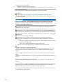
Warning notices
on the device
There are warning notices and safety symbols on the inside and outside of the in-
verter. These warning notices and safety symbols must not be removed or
painted over. They warn against incorrect operation, as this may result in serious
injury and property damage.
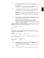
Safety symbols:
Danger of serious injury and prop-
erty damage due to incorrect opera-
tion
Do not use the functions described
here until you have fully read and
understood the following docu-
ments:
-These Operating Instructions
-All Operating Instructions for
the system components of the
photovoltaic system, especially
the safety rules
Dangerous electrical voltage
Wait for the capacitors to discharge.
Text of the warning notices:
WARNING!
Risk of electric shock!
Non-insulated inverter
Do not remove the cover. The device does not contain any user-serviceable parts.
Maintenance work must be carried out by a trained service technician.
Both AC and DC voltage sources terminate inside this device. Each circuit must
be turned off before carrying out maintenance work.
If the solar module is exposed to light, it will supply a DC voltage to the device.
Risk of electric shock due to energy stored in capacitors. Do not remove the cov-
er until all power supply sources have been switched off for at least 5 minutes.
11
EN-US

Ungrounded system: The DC cables in this PV system are not grounded and can
be live.
String fuses Only valid for the device types with the "Ecofuse" option:
The use of string fuses provides additional fuse protection for solar modules.
The maximum short circuit current ISC, the maximum module backfeed current
IR, and the specification of the maximum string fuse value in the module data
sheet of the respective solar module are decisive factors in the protection of the
solar module.
The maximum short circuit current ISC per terminal is 15 A.
The string fuse release current can be set to greater than 15 A if required.
However, a release current of 20 A must not be exceeded.
If the inverter is being operated with an external string collection box, the DC
connector kit 25 (item numbers 42,0201,4479 for DC+ and 42,0201,4480 for
DC-) must be used. In this case the solar modules are externally protected in the
string collection box and the metal bolts should be used in the inverter.
National regulations regarding fuse protection must be observed. The electrical
engineer carrying out the installation is responsible for the correct choice of
string fuses.
CAUTION!
Danger due to defective fuses.
This can result in fires.
▶Always replace defective fuses with new equivalent fuses.
The inverter is delivered with metal bolts as standard.
12

Criteria for the
Proper Selection
of String Fuses
In order to prevent premature tripping of the fuse during normal operation, it is
recommended that the following criteria be met per individual solar module
string when fusing-protecting the solar module strings:
-IN > 1.5 x ISC
-VN >/= maximum open circuit voltage of pv generator
-Fuse dimensions: Diameter 10 x 38 mm
INNominal current of the fuse
ISC Short circuit current for standard test conditions (STC) according to solar
module data sheet
VNNominal voltage of the fuse
NOTE!
The nominal current value of the fuse must not exceed the maximum fuse pro-
tection value specified in the solar module manufacturer's data sheet.
If a maximum fuse protection value is not specified, please request it from the
solar module manufacturer.
13
EN-US

Data Communication and Fronius Solar Net
Fronius Solar
Net and data in-
terface
Fronius developed Solar Net to make these system add-ons flexible and cap-
able of being used in a wide variety of different applications. Fronius Solar Net
is a data network that enables several inverters to be linked to the system add-
ons.
Fronius Solar Net is a bus system with ring topology. Just one suitable cable is
enough for communication between one or more inverters connected to Froni-
us Solar Net and a system add-on.
In order to clearly define each inverter in Fronius Solar Net, each inverter must
also be assigned an individual number.
You can assign individual numbers as per the "SETUP Menu" section.
Different system add-ons are automatically recognized by Fronius Solar Net.
In order to distinguish between several identical system add-ons, each one
must be assigned a unique number.
More detailed information on the individual system add-ons can be found in
the relevant operating instructions or on the internet at http://www.froni-
us.com
More detailed information on cabling Fronius DATCOM components can be
found at:
→ http://www.fronius.com/QR-link/4204101938
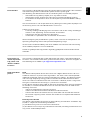
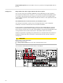
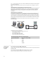
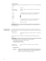
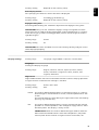
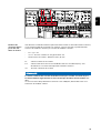
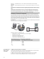
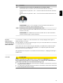
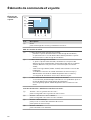
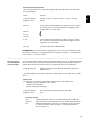
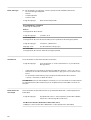
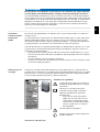
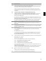
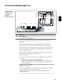
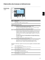
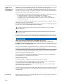
Data Communic-
ation Area
Depending on the version, the inverter can be fitted with the Fronius Dataman-
ager plug-in card (8).
14

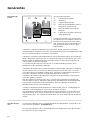
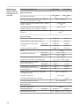
Ite
m Description
(1) Switchable multifunctional power interface.
For a more detailed explanation, see the section entitled "Explanation of
Multifunctional Power Interface" which follows
Use the 2-pin mating connector supplied with the inverter to connect to
the multifunctional power interface.
(2)
(3)
Fronius Solar Net/interface protocol IN connection
Fronius Solar Net/interface protocol OUT connection
Fronius Solar Net/interface protocol input and output for connecting to
other DATCOM components (e.g., inverter, Fronius Sensor Box, etc.)
When linking several DATCOM components, a termination plug must be
placed on each free IN and/or OUT connection of a DATCOM compon-
ent.
Two termination plugs are supplied with inverters with Fronius
Datamanager plug-in card.
(4) ‘Fronius Solar Net’ LED
indicates whether a power supply is available for Fronius Solar Net
(5) ‘Data transfer’ LED
flashes when accessing the USB thumb drive. The USB thumb drive
must not be removed during this time.
(6) USB A socket
for connecting a USB flash drive with a maximum size of
65 x 30 mm (2.6 x 2.1 in.)
The USB thumb drive can act as a data logger for an inverter. The USB
thumb drive is not part of the scope of supply for the inverter.
(7) Floating switch contact (relay) with mating connector
max. 250 V AC / 4 A AC
max. 30 V DC / 1 A DC
max. 1.5 mm² (AWG 16) cable cross section
Pin 1 = NO contact (Normally Open)
Pin 2 = root (Common)
Pin 3 = NC contact (Normally Closed)
For a more detailed explanation, see the “Menu items in the setup
menu/relay” section.
Use the mating connector supplied with the inverter to connect to the
floating switch contact.
(8) Fronius Datamanager with WLAN antenna
or
cover for option card slot
(9) Cover for option card slot
Explanation of
Multifunctional
Power Interface
Different switching variants can be connected to the multifunctional power inter-
face. These variants cannot be operated at the same time, however. For example,
if an S0 counter is connected to the multifunctional power interface, a signal
contact for surge protection cannot be connected, and vice versa.
15
EN-US

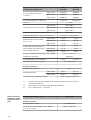
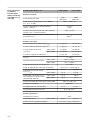
Pin 1 = measurement input: max. 20 mA, 100-ohm measurement resistor (appar-
ent ohmic resistance)
Pin 2 = max. short circuit current 15 mA, max. open circuit voltage 16 V DC or
GND
Switching Variant 1: Signal Contact for Surge Protection
The DC SPD (surge protection) option issues a warning or error on the display,
depending on the setting in the basic menu (signal input submenu). More de-
tailed information on the DC SPD option can be found in the Installation In-
structions.
Switching Variant 2: S0 Counter
A counter for recording self-consumption per S0 can be connected directly to
the inverter. This S0 counter can be placed at the feed-in point or in the con-
sumption branch. A dynamic power reduction can be set under the DSO Editor
menu subitem in the settings on the Fronius Datamanager website (see Fronius
Datamanager 2.0 Operating Instructions on the homepage at www.fronius.com)
IMPORTANT! Connecting an S0 meter to the inverter may require an inverter
firmware update.
Requirements for the S0 meter:
-Must meet standard IEC 62053-31 Class B
-Max. voltage: 15 V DC
-Max. current when ON: 15 mA
-Min. current when ON: 2 mA
-Max. current when OFF: 0.15 mA
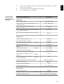
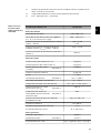
Recommended max. pulse rate of the S0 meter:
PV output kWp [kW] Max. pulse rate per kWp
30 1000
20 2000
10 5000
≤ 5.5 10,000
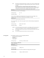
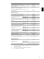
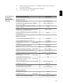
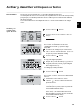
'Fronius Solar
Net' LED de-
scription
The ‘Fronius Solar Net‘ LED is illuminated:
Power supply for the data communication within the Fronius Solar Net/interface
protocol is OK
The ‘Fronius Solar Net‘ LED flashes briefly every 5 seconds:
Error in the data communication in the Fronius Solar Net
16

-Overcurrent (current flow > 3 A, e.g. due to a short circuit in Fronius Solar
Net ring)
-Undervoltage (no short circuit, voltage in Fronius Solar Net < 6.5 V, e.g. if too
many DATCOM components are in Fronius Solar Net and the electrical sup-
ply is insufficient)
In this case, an additional power supply is required for the Fronius DATCOM
components using an external power supply (43,0001,1194) on one of the
Fronius DATCOM components.
Check other DATCOM components to detect any undervoltage present.
After a shutdown due to overcurrent or undervoltage, the inverter tries to restore
the energy supply in the Fronius Solar Net every 5 seconds so long as there is an
error.
Once the error has been corrected, power is restored to Fronius Solar Net within
5 seconds.
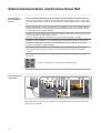
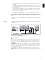
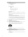
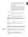
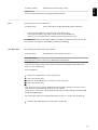
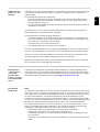
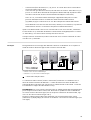
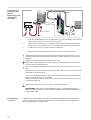
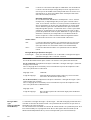
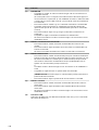
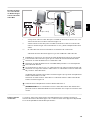
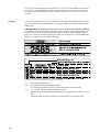
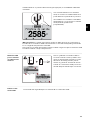
Example Logging and archiving inverter and sensor data using a Fronius Datamanager and
Fronius Sensor Box:
Data network with three inverters and one Fronius Sensor Box:
- inverter 1 with Fronius Datamanager
- inverter 2 and 3 without Fronius Datamanager.
= termination plug
External communication (Fronius Solar Net) takes place in the inverter via the
data communication area. The data communication area has two RS-422 inter-
faces: an input and an output. RJ45 plug connectors are used to establish the
connection.
IMPORTANT! Only one Fronius Datamanager in primary operation is permitted
per Fronius Solar Net Ring. Switch other Fronius Datamanagers to secondary op-
eration or remove them (see chapter "Controls, connections, and indicators on
the Fronius Datamanager 2.0").
Unused option card slots can be closed by replacing the cover (item number -
42,0405,2094), or an inverter without Fronius Datamanager (light version) can be
used.
17
EN-US

Fronius Datamanager 2.0
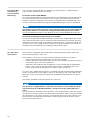
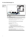
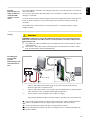
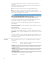
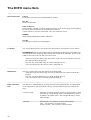
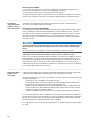
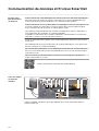
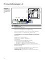
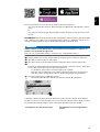
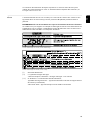
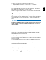
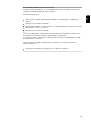
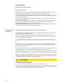
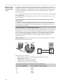
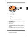
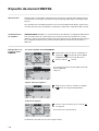
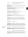
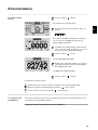
Controls, Con-
nections, and In-
dicators on the
Fronius
Datamanager 2.0
(5)
(1)
(6)(7)
(10) (8)(9)
(4)
(2)
(3)
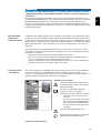
No. Function
(1) IP switch
For changing the IP address:
Switch position A
Specified IP address and opening the WLAN Access Point
Fronius Datamanager 2.0 uses fixed IP address 169.254.0.180 for a
direct connection to a PC via LAN.
If the IP switch is set to position A, an Access Point for a direct
WLAN connection to Fronius Datamanager 2.0 is also opened.
Access data for this Access Point:
Network name: FRONIUS_240.XXXXXX
Key: 12345678
Fronius Datamanager 2.0 can be accessed:
-via DNS name "http://datamanager"
-via IP address 169.254.0.180 for the LAN interface
-via IP address 192.168.250.181 for the WLAN Access Point
Switch position B
Assigned IP address
Fronius Datamanager 2.0 operates using an assigned IP address
(factory setting DHCP dynamic).
The IP address can be set at the Fronius Datamanager 2.0 website.
18

No. Function
(2) WLAN LED
-Flashes green: Fronius Datamanager 2.0 is in service mode
(IP switch on the Fronius Datamanager 2.0 plug-in card is set to po-
sition A or service mode was activated via the inverter display, the
WLAN Access Point is opened)
-Lights up green: There is an existing WLAN connection
-Alternately flashes green/red: The length of time for which the
WLAN Access Point is open after activation (1 hour) has been ex-
ceeded
-Lights up red: There is no existing WLAN connection
-Flashes red: Faulty WLAN connection
-Does not light up: Fronius Datamanager 2.0 is in slave mode
(3) Fronius Solar.web connection LED
-Lights up green: There is an existing connection to Fronius Sol-
ar.web
-Lights up red: There is no existing connection to Fronius Solar.web,
but one is required
-Does not light up: No connection to Fronius Solar.web is required
(4) Supply LED
-Lights up green: Sufficient power supply from Fronius Solar Net;
Fronius Datamanager 2.0 is operational.
-Does not light up: No power or insufficient power supply from
Fronius Solar Net - an external power supply is required
or
Fronius Datamanager 2.0 is in slave mode
-Flashes red: During an update process
IMPORTANT! Do not interrupt the power supply during an update
process.
-Lights up red: Update process failed
(5) Connection LED
-Lights up green: There is an active connection within Fronius Solar
Net
-Lights up red: There is an interrupted connection within Fronius Sol-
ar Net
-Does not light up: Fronius Datamanager 2.0 is in slave mode
(6) LAN connection socket
Ethernet interface colored blue for connecting the Ethernet cable
(7) I/Os
Digital inputs and outputs
D-
-
-
1
3
5
7
9
D+
+
+
0
2
4
6
8
I IO RS485
19
EN-US

No. Function
Modbus RTU 2-wire (RS-485):
D- Modbus data -
D+ Modbus data +
Int./ext. power supply
- GND
+ Uint/Uext
Output for internal voltage 12.8 V
or
input for external supply voltage
> 12.8 - 24 V DC (+ 20%)
Digital inputs: 0 - 3, 4 - 9
Voltage level: low = min. 0V - max. 1.8V; high = min. 3V - max. 24V DC (+
20%)
Input currents: dependent on input voltage; input resistance = 46 kOhm
Digital outputs: 0 - 3
Switching capacity when supplied by the Fronius Datamanager 2.0 plug-
in card: 3.2 W in total for all 4 digital outputs
Switching capacity when supplied by an external power supply with min.
12.8 - max. 24 V DC (+ 20%), connected to Uint/Uext and GND: 1 A, 12.8
- 24 V DC (depending on the external power supply) per digital output
The connection to the I/Os is made via the supplied mating connector.
(8) Antenna plug
For screwing on the WLAN antenna
(9) Modbus termination switch (for Modbus RTU)
Internal bus termination with 120-ohm resistance (yes/no)
Switch in "on” position: Termination resistance of 120 Ohm active
Switch in "off” position: No termination resistance active
IMPORTANT! The termination resistance must be active for the first
and last device in an RS-485 bus.
(10) Fronius Solar Net master/slave switch
For switching between master and slave mode within a Fronius Solar
Net ring
IMPORTANT! All LEDs on the Fronius Datamanager 2.0 plug-in card are
off in slave mode.
20
La page est en cours de chargement...
La page est en cours de chargement...
La page est en cours de chargement...
La page est en cours de chargement...
La page est en cours de chargement...
La page est en cours de chargement...
La page est en cours de chargement...
La page est en cours de chargement...
La page est en cours de chargement...
La page est en cours de chargement...
La page est en cours de chargement...
La page est en cours de chargement...
La page est en cours de chargement...
La page est en cours de chargement...
La page est en cours de chargement...
La page est en cours de chargement...
La page est en cours de chargement...
La page est en cours de chargement...
La page est en cours de chargement...
La page est en cours de chargement...
La page est en cours de chargement...
La page est en cours de chargement...
La page est en cours de chargement...
La page est en cours de chargement...
La page est en cours de chargement...
La page est en cours de chargement...
La page est en cours de chargement...
La page est en cours de chargement...
La page est en cours de chargement...
La page est en cours de chargement...
La page est en cours de chargement...
La page est en cours de chargement...
La page est en cours de chargement...
La page est en cours de chargement...
La page est en cours de chargement...
La page est en cours de chargement...
La page est en cours de chargement...
La page est en cours de chargement...
La page est en cours de chargement...
La page est en cours de chargement...
La page est en cours de chargement...
La page est en cours de chargement...
La page est en cours de chargement...
La page est en cours de chargement...
La page est en cours de chargement...
La page est en cours de chargement...
La page est en cours de chargement...
La page est en cours de chargement...
La page est en cours de chargement...
La page est en cours de chargement...
La page est en cours de chargement...
La page est en cours de chargement...
La page est en cours de chargement...
La page est en cours de chargement...
La page est en cours de chargement...
La page est en cours de chargement...
La page est en cours de chargement...
La page est en cours de chargement...
La page est en cours de chargement...
La page est en cours de chargement...
La page est en cours de chargement...
La page est en cours de chargement...
La page est en cours de chargement...
La page est en cours de chargement...
La page est en cours de chargement...
La page est en cours de chargement...
La page est en cours de chargement...
La page est en cours de chargement...
La page est en cours de chargement...
La page est en cours de chargement...
La page est en cours de chargement...
La page est en cours de chargement...
La page est en cours de chargement...
La page est en cours de chargement...
La page est en cours de chargement...
La page est en cours de chargement...
La page est en cours de chargement...
La page est en cours de chargement...
La page est en cours de chargement...
La page est en cours de chargement...
La page est en cours de chargement...
La page est en cours de chargement...
La page est en cours de chargement...
La page est en cours de chargement...
La page est en cours de chargement...
La page est en cours de chargement...
La page est en cours de chargement...
La page est en cours de chargement...
La page est en cours de chargement...
La page est en cours de chargement...
La page est en cours de chargement...
La page est en cours de chargement...
La page est en cours de chargement...
La page est en cours de chargement...
La page est en cours de chargement...
La page est en cours de chargement...
La page est en cours de chargement...
La page est en cours de chargement...
La page est en cours de chargement...
La page est en cours de chargement...
La page est en cours de chargement...
La page est en cours de chargement...
La page est en cours de chargement...
La page est en cours de chargement...
La page est en cours de chargement...
La page est en cours de chargement...
La page est en cours de chargement...
La page est en cours de chargement...
La page est en cours de chargement...
La page est en cours de chargement...
La page est en cours de chargement...
La page est en cours de chargement...
La page est en cours de chargement...
La page est en cours de chargement...
La page est en cours de chargement...
La page est en cours de chargement...
La page est en cours de chargement...
La page est en cours de chargement...
La page est en cours de chargement...
La page est en cours de chargement...
La page est en cours de chargement...
La page est en cours de chargement...
La page est en cours de chargement...
La page est en cours de chargement...
La page est en cours de chargement...
La page est en cours de chargement...
La page est en cours de chargement...
La page est en cours de chargement...
La page est en cours de chargement...
La page est en cours de chargement...
La page est en cours de chargement...
La page est en cours de chargement...
La page est en cours de chargement...
La page est en cours de chargement...
La page est en cours de chargement...
La page est en cours de chargement...
La page est en cours de chargement...
La page est en cours de chargement...
La page est en cours de chargement...
La page est en cours de chargement...
La page est en cours de chargement...
La page est en cours de chargement...
La page est en cours de chargement...
La page est en cours de chargement...
La page est en cours de chargement...
La page est en cours de chargement...
La page est en cours de chargement...
La page est en cours de chargement...
La page est en cours de chargement...
La page est en cours de chargement...
La page est en cours de chargement...
La page est en cours de chargement...
La page est en cours de chargement...
La page est en cours de chargement...
La page est en cours de chargement...
La page est en cours de chargement...
La page est en cours de chargement...
La page est en cours de chargement...
La page est en cours de chargement...
La page est en cours de chargement...
-
 1
1
-
 2
2
-
 3
3
-
 4
4
-
 5
5
-
 6
6
-
 7
7
-
 8
8
-
 9
9
-
 10
10
-
 11
11
-
 12
12
-
 13
13
-
 14
14
-
 15
15
-
 16
16
-
 17
17
-
 18
18
-
 19
19
-
 20
20
-
 21
21
-
 22
22
-
 23
23
-
 24
24
-
 25
25
-
 26
26
-
 27
27
-
 28
28
-
 29
29
-
 30
30
-
 31
31
-
 32
32
-
 33
33
-
 34
34
-
 35
35
-
 36
36
-
 37
37
-
 38
38
-
 39
39
-
 40
40
-
 41
41
-
 42
42
-
 43
43
-
 44
44
-
 45
45
-
 46
46
-
 47
47
-
 48
48
-
 49
49
-
 50
50
-
 51
51
-
 52
52
-
 53
53
-
 54
54
-
 55
55
-
 56
56
-
 57
57
-
 58
58
-
 59
59
-
 60
60
-
 61
61
-
 62
62
-
 63
63
-
 64
64
-
 65
65
-
 66
66
-
 67
67
-
 68
68
-
 69
69
-
 70
70
-
 71
71
-
 72
72
-
 73
73
-
 74
74
-
 75
75
-
 76
76
-
 77
77
-
 78
78
-
 79
79
-
 80
80
-
 81
81
-
 82
82
-
 83
83
-
 84
84
-
 85
85
-
 86
86
-
 87
87
-
 88
88
-
 89
89
-
 90
90
-
 91
91
-
 92
92
-
 93
93
-
 94
94
-
 95
95
-
 96
96
-
 97
97
-
 98
98
-
 99
99
-
 100
100
-
 101
101
-
 102
102
-
 103
103
-
 104
104
-
 105
105
-
 106
106
-
 107
107
-
 108
108
-
 109
109
-
 110
110
-
 111
111
-
 112
112
-
 113
113
-
 114
114
-
 115
115
-
 116
116
-
 117
117
-
 118
118
-
 119
119
-
 120
120
-
 121
121
-
 122
122
-
 123
123
-
 124
124
-
 125
125
-
 126
126
-
 127
127
-
 128
128
-
 129
129
-
 130
130
-
 131
131
-
 132
132
-
 133
133
-
 134
134
-
 135
135
-
 136
136
-
 137
137
-
 138
138
-
 139
139
-
 140
140
-
 141
141
-
 142
142
-
 143
143
-
 144
144
-
 145
145
-
 146
146
-
 147
147
-
 148
148
-
 149
149
-
 150
150
-
 151
151
-
 152
152
-
 153
153
-
 154
154
-
 155
155
-
 156
156
-
 157
157
-
 158
158
-
 159
159
-
 160
160
-
 161
161
-
 162
162
-
 163
163
-
 164
164
-
 165
165
-
 166
166
-
 167
167
-
 168
168
-
 169
169
-
 170
170
-
 171
171
-
 172
172
-
 173
173
-
 174
174
-
 175
175
-
 176
176
-
 177
177
-
 178
178
-
 179
179
-
 180
180


Fronius 24.0-3 480 Symo Advanced Le manuel du propriétaire
- Taper
- Le manuel du propriétaire
dans d''autres langues
Documents connexes
-
Fronius 150 Mode d'emploi
-
Fronius TransPocket Mode d'emploi
-
Fronius 1 Plus 2 GEN24 Mode d'emploi
-
Fronius Symo GEN24 Mode d'emploi
-
Fronius TS 65A-3 Mode d'emploi
-
 Fronius Eco 99-3-P Mode d'emploi
-
 Fronius Tauro Mode d'emploi
-
Fronius Symo 3.0-3-S Manuel utilisateur
-
Fronius 50kA-3 Guide d'installation
-
 Fronius D1-F1 Mode d'emploi


Autres documents
-
 versa TMUE910GL 3G Module Label Diagram Manuel utilisateur
-
STECA StecaGrid 2010+ Master Installation And Operating Instructions Manual
-
SMA SUNNY TRIPOWER 12000TL-US Guide d'installation
-
ABB PVI-3.0-OUTD-S-US Manuel utilisateur
-
SolarEdge PB250-AOB Guide d'installation
-
Samlexpower EVO-1224F Le manuel du propriétaire
-
SMA SUNNY BOY STORAGE 3.8-US Guide d'installation
-
Magnum Energy MS2012 Manuel utilisateur
-
Morningstar Prostar MPPT Manuel utilisateur
-
