LG LMV1751ST Mode d'emploi

Catégorie
Micro-ondes
Taper
Mode d'emploi
Website: http://www.lg.com
MICROWAVE OVEN
INSTALLATION INSTRUCTIONS
PLEASE READ AND SAVE THESE INSTALLATION INSTRUCTIONS.
MFL37192908_02
2
Your Safety First
BEFORE YOU START
• Proper installation is the installer's responsibility!
Proper installation by a qualified technician or installer is recommended.
NOTE: Vent grille appearance varies by model.
BE SURE TO READ THE FOLLOWING SAFETY INSTRUCTIONS:
Model Number Plate
Model Number Plate
Figure 1
Mounting Plate Mounting Plate
or
For Your Safety
W A R N I N G
Figure 2
• Avoid Electric Shock!
– Before you drill into the wall, note where electrical outlets are and where electrical wires might be concealed
behind the wall. YOU COULD GET AN ELECTRIC SHOCK if you contact electrical wires with your drill bit.
– Locate and disconnect the power to any electrical circuits that could be affected by installing this oven.
IF YOU DO NOT DISCONNECT THE POWER, YOU COULD GET AN ELECTRIC SHOCK.
• ELECTRICAL RATING OF THIS OVEN : 120V AC 60Hz.
– You need a DEDICATED 120V, 60Hz, AC only, 15 or 20A, fused electrical supply (located in the cabinet
above the microwave as close as possible to the microwave) serving only the microwave.
• THIS APPLIANCE MUST BE GROUNDED!
If there is an electrical short circuit, grounding reduces the risk of electric
shock by providing an escape wire for the electric current. This appliance
is equipped with a cord having a grounding wire with a grounding plug.
Place the plug into a properly installed and grounded outlet. See Figure 3.
Do not use an extension cord.
Keep the power cord dry and do not pinch or crush it.
Failure to follow this instruction may cause a fire hazard.
• DO NOT, UNDER ANY CIRCUMSTANCES, REMOVE THE
POWER SUPPLY CORD GROUNDING PRONG!
This appliance MUST be grounded!
PROPERLY POLARIZED AND
GROUNDED OUTLET
Three-Pronged (Grounding) Plug
Figure 3
If you use the grounding plug improperly, you risk electric shock and/or fire!
Check with a qualified electrician if you are not sure whether the oven is properly grounded or if you do not
completely understand the grounding instructions.
DO NOT USE A FUSE IN THE NEUTRAL OR GROUNDING CIRCUIT.
Improper grounding could result in electric shock, fire or other personal injury.
– Read the entire manual before you begin. The model number label is located on the oven front.
See Figure 1. The mounting plate is located on the upper packing. See Figure 2.
w
• This oven should not be installed or located by anyone except properly qualified service personnel.
• You will need TWO people to install this oven. It is heavy and could cause personal injury if not handled
properly.
W ARNI N G
w
w
W ARNI N G
Your Safety First
• MAKE SURE YOU HAVE ENOUGH SPACE AND SUPPORT.
– Mount the oven against a flat, vertical wall, so it is supported by the wall. The wall should be constructed of
minimum 2" x 4" wood studding and 3/8" thick drywall or plaster/lath.
– ATTACH (See note on page 4) the two lag screws supporting the oven to a vertical, 2" x 4" wall stud.
– DO NOT mount the microwave oven to an island or peninsula cabinet.
– BE SURE the upper cabinet and rear wall structures can support 150 lbs., plus the weight of any
items you place inside the oven or upper cabinet.
– Locate the oven away from strong draft areas, such as windows, doors, and strong heating vents.
– BE SURE you have enough space. See Figure 4 below for minimum vertical and horizontal clearance.
Before you begin installing the oven, PLACE A PIECE OF THE CARTON OR OTHER HEAVY
MATERIAL (a blanket) over the countertop or cooktop to protect it. Do not use a plastic cover.
Failure to protect these surfaces could result in property damage.
30" min. cabinet opening width
30" min. clearance from bottom
of cabinet to cooking surface
or countertop before installation.
Grounded Outlet
(inside upper cabinet)
Power Supply Cord Hole
(Use templates included
with installation instructions)
If you do not mount the oven as instructed,
you risk personal injury and/or property damage.
NOTE: Maximum cabinet depth is 13".
SAVE THESE INSTRUCTIONS FOR THE LOCAL ELECTRICAL INSPECTOR'S USE.
• DO NOT EXPOSE YOURSELF TO EXCESSIVE MICROWAVE ENERGY!
– DO NOT try to operate the microwave oven with the door open.
– DO NOT tamper with or defeat the safety interlocks.
– DO NOT place objects between the microwave oven front face and the door.
– DO NOT allow soil or cleaner residue to build up on the flat surfaces around
– DO NOT operate the microwave oven if it is damaged.
– The microwave oven door must close properly to operate safely.
– DO NOT USE THE MICROWAVE OVEN:
the microwave oven door.
If the door is bent.
If the hinges or latches are broken or loose.
If the door seals, sealing surfaces or glass is broken.
– DO NOT ATTEMPT TO ADJUST OR REPAIR THE OVEN YOURSELF!
It should be adjusted and repaired by a qualified technician who can check for microwave leakage after
repairing the oven.
If you do not use the microwave oven as instructed,
you could be exposed to excessive microwave energy.
W ARNI N G
w
W ARNI N G
w
w
CAUTION
3
Figure 4
4
Parts, Tools, Materials
THE FOLLOWING PARTS ARE SUPPLIED WITH THE OVEN:
NOTE: Depending on your ventilation requirements, you may not use all of these parts.
Damper/duct connector
(for roof venting or wall venting installation)
Not Actual Size (2 pieces must be assembled as
shown) Not used if venting into kitchen.
One power cord clamp and
One dark-colored mounting screw
(to hold the power cord)
Actual Size
1/4" x 2" lag screws - Actual Size
(for wall stud holes)
Two 1/4" x 3" toggle bolts - Actual Size
(for drywall holes)
Two 1/4" x 3" bolts - Actual Size
(for securing to the upper cabinet
Two 1/4" x 3" bolts - Actual Size
(for securing to the upper cabinet)
Two tapping screws - Actual Size
(for attaching the damper duct connector)
One upper cabinet template- Not Actual Size
One rear wall template- Not Actual Size
(1 piece mounting plate only)
One power cord clamp bushing - Actual Size (for the cord hole in a metal upper cabinet)
NOTE: You need to install at least one lag screws into a 2" x 4" stud and three anchor bolts into the wall.
and the mounting area must meet the 150 lbs. weight requirement.
Two
)
One mounting plate - Not Actual Size (for supporting the Microwave Oven )
WARNING - TO REDUCE THE RISK OF FIRE AND ELECTRIC SHOCK,
INSTALL AT LEAST 13-3/4 INCHES ABOVE A COOKTOP(OR RANGE)
SUITABLE FOR USE ABOVE GAS OR ELECTRIC
COOKING EQUIPMENT 36 INCHES OR LESS WIDE.
APTO PARA SU USO SOBRE EQUIPOS ELÉCTRICOS O
A GAS CON ANCHO DE 36 PULGADAS (90CM) O INFERIOR
ADVERTENCIA - PARA REDUCIR EL RIESGO DE INCENDIO Y DE DESCARGA ELÉCTRICA,
INSTALE AL MENOS A 13-3/4 PULGADAS (35CM) SOBRE LA VITROCERÁMICA (O FOGÓN)
5
Parts, Tools, Materials
Clear Tape
(for taping the templates to the wall)
Phillips Screwdriver
(for the screws)
Flat Blade Screwdriver
(for the toggle bolts)
Plumb Line
Measuring Tape
(metal preferred)
Duct Tape
Caulking Gun and Caulk
Stud Finder or Thin Nail
Saber Saw
(for cutting vent holes for roof
or wall venting)
Keyhole Saw (for the power cord hole)
You will need the following tools and materials for the installation:
Carton or other heavy material such as a blanket for covering the counter top.
3/8" and 3/4" wood drill bits
1/2" and 3/16"
drill bits
Electric Drill
Small Side Cutters(Nipper) or Tin Snips
If you have brick or masonry walls, you will need special hardware and tools.
The ductwork you need for the installation is not included. All wall and roof caps must have a back-draft damper.
(Shown on page 4).
Wear proper gloves to protect your hands from injury.
Gloves
Pencil
6
STEP 1: Prepare The Electrical Connection
Improper grounding could result in electric shock or other personal injury.
1. Locate the grounded electric outlet for this oven in the
cabinet above the oven, as shown in Figure 5.
NOTE: The outlet should be on a circuit dedicated to the
microwave oven (120V, 60 Hz., AC only) with a 15 or 20A
fused electrical supply.
IMPORTANT: If you do not have the proper wall outlet,
you MUST have one installed by a qualified electrician.
2. You will cut the hole for the power supply cord (shown in
Figure 5) later when you prepare the wall and upper cabinet in
Step 4.
NOTE: Do not use an extension cord.
Keep the power cord dry and do not pinch or crush it.
DO NOT, UNDER ANY CIRCUMSTANCES, REMOVE THE POWER SUPPLY CORD
GROUNDING PRONG!
This appliance MUST be grounded!
AVOID ELECTRIC SHOCK! THIS APPLIANCE MUST BE GROUNDED!
Upper
Cabinet
Power-Supply-Cord Hole
Figure 5
Grounded Outlet
(Inside Cabinet)
W ARNING
w
W ARNING
w
7
STEP 2: Prepare The Venting System
THIS OVEN MUST BE PROPERLY VENTED!
NOTE: The ductwork you need for outside ventilation is not included with your oven. The standard ductwork
fittings and length are shown in Figure 10, page 8.
You may vent your oven in one of three ways. However, do NOT vent into a wall cavity, an attic, or an unused
area.
Roof-venting If your oven is located on an outside wall near the roof, as in Figure 7 (3 1/4" x 10" duct) and
Figure 9 (6" round duct.)
Wall-venting If your oven is located on an outside wall of your house, as in Figure 6 (3 1/4" x 10" duct) and
Figure 9 (6" round duct.)
Room-venting If your oven is located on an inside wall of your house, as in Figure 8.
NOTE: If you choose the rear exhaust method (roof or wall-venting), be sure there is enough clearance within the
wall for the exhaust duct.
REMEMBER AS YOU INSTALL THE
VENTING:
Keep the length of the ductwork and the number
of elbows to a minimum to ventilate your oven
efficiently. See examples on page 8.
Keep the size of the ductwork the same.
Do not install two elbows together.
Use duct tape to seal all joints in the duct system.
Use caulking to seal the exterior wall or roof
opening around the cap.
Cabinet
Oven
Wall Mounting
Through-the-wall Duct
Wall Cap
3 1/4"x10"
Duct
Cabinet
Oven
Figure 6
Wall Venting
Through-the-roof
3 1/4"x10"
Duct
Roof Cap
Roof Venting
Cabinet
Oven
Figure 7
Roof Venting
Figure 8
Room Venting
6"min diameter
Round Duct
3 1/4" to Round
Duct Transition
3 1/4" to Round
Ductwork Transition
Roof Cap
Wall Cap
Elbow
Figure 9
W ARNING
w
After installation, you should check outside hood opening and operation.
When you install the oven, please refer to the Installation Manual.
For the outside hood opening position and size refer to the upper cabinet template or rear wall template.
8
STEP 2: Prepare The Venting System
Standard Fittings
NOTE: If the existing duct is round, you must use a rectangular-to-round adapter, with a rectangular 3" extension
duct installed between the damper assembly and the adapter to prevent the exhaust dampers sticking.
Duct Length
The total length of the duct system, including straight duct, elbows, transitions, and wall or roof caps must not
exceed 140 feet.
For best performance, do not use more than three 90 degree elbows, and keep the length as short as possible.
Below are the standard fittings and their equivalent length in feet.
To calculate the equivalent length of each duct piece used, see the examples below.
Figure 10
6ft.
2ft.
2ft.
wall cap
6ft.
transition
wall cap
For 3 1/4" x 10" SYSTEMS
1 3 1/4 x 10 90° elbow = 25 ft.
1 Wall Cap = 40 ft.
8 feet straight duct = 8 ft.
TOTAL LENGTH = 73 ft.
1 transition = 5 ft.
2 90° elbows = 20 ft.
1 Wall Cap = 40 ft.
8 feet straight = 8 ft.
TOTAL LENGTH = 73 ft.
For 6" ROUND SYSTEMS
3 1/4 x 10
to 6" = 5 ft.
90˚elbow
= 10 ft
45˚elbow
= 5 ft
3 1/4 x 10
wall cap
= 40 ft
3 1/4 x 10
flat elbow
= 10 ft
3 1/4 x 10 roof
cap = 24 ft
3 1/4 x 10 90˚
elbow = 25 ft
1 2 3
4 5 6 7
Examples
9
STEP 3: Prepare The Venting Blower
Your microwave oven is shipped with the blower assembled fo room-vented. You need to adjust the blower if your
want wall-venting or roof-vented installation.
DO NOT PULL OR STRETCH THE BLOWER WIRING! Pulling and stretching the blower wiring could result in
electric shock.
1. Remove any shipping materials and parts from inside the
microwave oven. Set them aside for later use.
2. Cover the counter top or cooktop with a thick, protective
covering to protect it from damage and dirt. See Figure 11.
NOTE: If you have a free-standing range, disconnect
it, move it onto a piece of cardboard or hardboard and
pull it away from the wall, so that you can get closer to
the upper cabinet and back wall for easier measuring
and drilling.
3. Locate the exhaust adaptor, grease filters and hardware packet.
4. At this point, remove any adhesive tape (if there is any), on the
exhaust adaptor, the grease filters and the power supply cord.
ROOM-VENTED INSTALLATION:
This oven is shipped assembled for room-vented.
You need togo to STEP 4: PREPARE THE WALL & UPPER CABINET
located on page 13 .
A thick, protective
covering
Figure 11
ELECTRIC SHOCK HAZARD! UNPLUG UNIT BEFORE WORKING ON IT.
W A RNIN G
W ARN I N G
FIRE HAZARD! CORRECTLY INSTALL THE VENT FAN BEFORE USE .
When changing the vent fan position for a rear wall vent or roof vent:
1. Properly align the ventilation fan openings and blower plate knockouts.
2. Ventilation fan openings should be completely exposed to the outside.
3. After installation, check the air ventilation path. Refer to page 7 Figures 6-8 for proper vent selection.
Improper installation can cause problems such as:
1. Inability to assemble blower plate or ventilation motor correctly.
2. Abnormal noise during product operation.
3. Weak ventilation.
4. Product overheating - possibility of product breakdown or fire.
Do not remove the packing tape on the slide-out vent.
NOTE: Set the product down on a flat surface only.
Mounting plate
Mounting plate
screws
Control Panel Side
STEP 3: Prepare The Venting Blower
WALL-VENTING INSTALLATION:
2. Carefully lift the blower unit out of the microwave oven.
3. Use side cutters or tin snips to cut and remove knockouts
B from Back plate. Discard knockouts. Be careful not to
distort the plate. See Figure 14.
4. Reassemble the blower wire. See Figure 15.
5. Rotate and reinstall the blower unit so that the exhaust
ports face the rear of the cabinet and are aligned with the
rear cut-outs. See Figures 16 & 17.
7. Insert the tabs on each side of the damper into the holes
at the inside rear of the adaptor.
Attach the exhaust adaptor to the back plate wall side.
Push in securely until it is past the top locking tabs
and in the lower locking tabs. Take care to assure
the damper hinge is installed so that it is at the top
and that the damper swings freely. See Figure 19.
Figure 13
Blower
Unit
Exhaust Ports
Figure 14
Figure 15
Figure 17
Figure 16
Exhaust
Ports
– 10 –
Slide exhaust
adaptor into
guides on
rear panel.
Exhaust Adaptor
Damper
(hinge side up)
Locking
Tabs
Guides
Figure 18
See Figure 13.
Parts B
Knockouts Parts B
Figure 19
or
Figure 1
Cover plate
Blower Plate
Mounting Screw
Blower Plate
Back Plate
Parts B
Blower Unit
Blower Unit
Mounting Screw
Cover plate
1. Remove one cover plate mounting screw and cover plate
Remove one or several blower plate mounting screw(s) and
the blower plate.
Remove the cover plate and one or two blower unit mounting
screw(s). See Figure12
6. Reattach the blower plate to cabinet so the exhaust ports
and blower plate opening are aligned. Attach with one
blower unit mounting screw and then one or several blower
plate mounting screw(s). Reattach the cover plate with screw
on the blower plate, See Figure 18.
Blower Plate
Mounting Screw
Blower Plate
Back Plate
Blower Unit
Exhaust Ports
Blower Unit
Blower Unit
Mounting Screw
Cover plate
STEP 3: Prepare The Venting Blower
Roof-Vented Installation:
2. Carefully lift the blower unit out of the microwave
3. Rotate blower unit 90° so the exhaust ports face the top of
the cabinet. See Figure 21.
4. Place blower unit back into microwave oven.
Figure 22
blower plate
Knockouts “A”
Figure 21
Figure 24
– 11 –
Blower Unit
90°
5. Use side cutter or tin snips to cut and remove knockouts "A"
from blower plate. Discard knockouts. Be careful notto distort
the plate. See Figure 22.
Figure 20
Figure 23
1.
Remove one cover plate mounting screw and cover plate.
Remove one or several blower plate mounting screw(s)
and the blower plate.
Remove the cover plate and one or two blower unit
mounting screw(s). See Figure 20.
Cover plate
Blower Plate
Mounting Screw
Blower Plate
Back Plate
Parts B
Blower Unit
Blower Unit
Mounting Screw
Cover plate
6. Reattach the cover plate on the back.
Reattach blower plate to microwave oven.
Attach with the one blower unit mounting screw and then
he blower plate mounting screw s .
See Figure 23.
7. Insert the tabs on each side of the damper into the holes
at the inside rear of the adaptor.
Attach the exhaust adaptor to the blower plate with the two
tapping screws provided. See Figure 24.
Make sure that the damper swings freely.
blower unit
mounting screws
blower unit
Cover plate
blower plate
blower plate
mounting
screws
Damper
Back of
Oven
Exhaust
Adaptor
Blower Plate
Cover plate
(This step is optional, depending on the model.)
(Optional)
12
STEP 4: Prepare The Wall & Upper Cabinet
To avoid personal injury or property damage, do not attempt to install this microwave
oven if you cannot find a wall stud. Consult a carpenter or contractor.
Mounting Plate
Measure And Track/Tape Up The Templates
1. Using a plumb line and (metal) measuring tape, find and
mark the vertical center line on the back wall, as in
Figure 25.
2. Find and mark one or two points where the studs are on
the wall. (Studs are normally 16 inches apart). Then
measure and mark the stud locations. If you cannot find
any wall stud, consult a local building contractor.
3. Draw a vertical line on the wall at the center of th 30
wide space.
NOTE: Be sure the minimum width is 30 inches.
Figure 25
Figure 26
4. Center the rear wall template in the space by lining up the
plumb line on wall with centerline on template.Then securely
tape or tack the rear wall template in place.Make sure the
minimum width is 30 inches and that the top of the rear
wall template is located a minimum of 30 inches above
the cooking surface. See Figure 25.
NOTE: If the cabinets are not plumb, adjust the rear wall
template to the cabinets. If the front edge of the
cabinet is lower than the back edge, adjust the
template to be level with the cabinet front.
5. Measure the bottom of the upper cabinet frame. Trim
edges A, B, and C on the upper cabinet template
so that the template will fit on the bottom of the upper
cabinet. If upper cabinet has a recessed frame, trim the
template so it fits inside the recessed area. Align the
centerline of the upper cabinet template with the
centerline of the rear wall template, then securely tape or
tack the upper cabinet template in place. See Figure 26.
DO NOT ATTEMPT TO INSTALL THE MICRO-
WAVE OVEN IF YOU CANNOT FIND A WALL
STUD.
CAUTION
W ARNING
w
w
Upper Cabinet Template
13
STEP 4: Prepare The Wall & Upper Cabinet
Drill The Holes In The Wall And Upper Cabinet.
1. Drill holes on the circles. If there is a stud, drill a 3/16
"
hole
for lag screws. If there is no stud, drill a 3/4
"
hole for toggle
bolts. Make sure to use at least 1 lag screw in a stud, and
2 toggle screws in the drywall or the plaster.
2. Drill a 3/8” hole at points J and K on the upper cabinet
template.
NOTE: If the bottom of the upper cabinet is recessed 3/4
"
or more, you will need 2
"
x 2
"
filler blocks (not
included) to provide additional support for the bolts.
See Figure 27.
Align filler blocks over the two openings in the top
of the microwave oven cabinet and attach to the
cabinet with masking tape. See Figure 28.
3. Cut or drill a 2
"
diameter hole at the area marked M. Power
supply cord hole on the upper cabinet template. If the upper
cabinet is metal, you will need to cover the edge of the hole
with the power supply cord bushing (supplied) to prevent
damage to the cord from the rough metal edge.
4. Cut out the venting areas (with the saber saw):
Figure 27
Figure 28
Cabinet Front
Cabinet
Bottom Shelf
Filler Block
Filler
Block
Mark the center of each filler block and drill a 3/8
diameter hole at the marks.
Roof-Venting: cut out the shaded area marked L on the
upper cabinet template.
Room-Venting: go to STEP 5, INSTALL THE MOUNTING
PLATE, located on page 14.
5. Complete whichever venting system you have chosen. Use
caulking compound to seal the exterior wall or roof opening
around the wall cap or roof cap.
To avoid risk of personal injury, electric shock or death:
Note where electrical outlets and electrical wires are before you drill into the wall.
Locate and disconnect power to any electrical circuits that could be affected by
installing this oven.
To avoid risk of personal injury, electric shock or death, cover the edge of the power
supply cord hole with the power supply cord bushing.
Wall-Venting: Cut out the shaded area marked F on the
REAR WALL TEMPLATE.
W ARNING
w
W ARNING
w
– 14 –
STEP 5: Install The Mounting Plate
C
B
A
The Oven Must Be Connected To At Least One
Wall Stud.
4. Attach the plate to the wall. To use spring toggle head bolts:
Remove the toggle wings from the bolts. Insert the bolts into
the mounting plate and replace the spring toggle head to 3/4
past the bolt ends. Insert the spring toggle head into the
holes in the wall to mount the plate. You may pull forward on
the plate to help in tightening the toggle bolts. Tighten all
bolts. See Figure 30.
3. Remove the template from the rear wall.
1. Center the rear wall template in the space by lining up the
plumb line on wall with centerline on template.Then securely
tape or tack the rear wall template in place.Make sure the
minimum width is 30 inches and that the top of the rear
wall template is located a minimum of 30 inches above
the cooking surface. See Figure 25.
NOTE: If the cabinets are not plumb, adjust the rear wall
template to the cabinets. If the front edge of the
cabinet is lower than the back edge, adjust the
template to be level with the cabinet front.
a stud. If there is a stud, drill a 3/16 hole for lag screws.
If there is no stud, drill a 5/8 hole for toggle bolts.
These holes must be used for mounting. If the holes are
not used, the installation will not be secure. Installer must
use these holes for proper installation. See Figure 29.
Use toggle bolts through these holes, unless one of them
lines up with a stud. Use a wood screw for studs.
Make sure to use at least 1 lag screw in a stud,
and 2 toggle bolts in the drywall or the plaster.
2. Drill holes at points A, B. Drill the third hole inside area C,
through one of the bottom holes to match the location of
NOTE: Cut out the shaded area marked F on the REAR
WALL TEMPLATE for wall-venting.
Figure 30
Figure 29
Wall
Mounting
Plate
Space More Than Wall Thickness
Bolt
End
Toggle Bolt
Toggle Wings1
3/16 Hole on Studs
5/8 Hole on Drywall Only
Minimum 66
From the Floor
For Wall -
Venting Only
Draw Lines
on Studs
Draw
Center Line
Center Line
Mounting Plate
Support Tab
Support Tab
STEP 6: Attach The Oven To The Wall
– 15 –
1. Carefully lift microwave oven and hang it on support tabs
(See Figure 29) at the bottom of the mounting
plate.Reaching through upper cabinet, thread
power supply cord through the power supply cord
hole in the bottom of the upper cabinet.
See Figure 31.
2. Rotate the microwave oven upward so the top of the
oven is against the bottom of the upper cabinet or cabinet
frame.
3. Then insert a bolt down through each hole in the
upper cabinet bottom.See Figure 32.
Tighten the bolts until the gap between the upper cabinet
and microwave oven is closed.
Figure 31
Figure 32
Power Cord
Power Cord
Hole
To avoid risk of personal injury or property damage, you will need two people to
install this microwave oven.
W A R N I N G
4. Roof venting installation: See Figure 33.
Install ductwork through the vent opening in the
upper cabinet. Use caulking gun to seal the exterior roof
opening around the exhaust cap. See Figure 7 on page 7.
5. Use the power supply cord clamp to bundle the power
supply cord. Install the power supply cord clamp, using a
screw as shown in Figure 34, to the inside of the cabinet.
6. Grasp the filter screen with one hand holding the ring and the
other hand holding the opposite end. Insert the end of the
filter screen without ring into the opening and slide
towards the side of the microwave oven. Insert ring end of
filter screen into the opening and slide entire screen
towards the center of the microwave until screen is
securely in position. Repeat for other filter screen. See
Figure 35.
7. Plug in the power supply cord.
8. Read your Owner’s Manual, then check the operation of
your microwave oven.
Damper
Power
supply
Cord
Clamp
Figure 33
Figure 34
Figure 35
1
2
3
1
2
NOTE:
Do not apply force directly to the outside bottom surface of the product.
The slide-out vent latch may be damaged if force is applied directly to the center bottom of the product.
● Set the product down on a flat surface only.
During unpacking, gently set the product onto a flat surface such as a
kitchen table or counter.
● Do not lift or support the product by the bottom center surface.
The product is best handled by the bottom sides near the legs.
● Do not remove the packing tape on the slide-out vent during
installation.
Once the product is fully installed, remove the tape and check that the vent
easily slides open and closed with a push.
FOUR À MICRO-ONDES
INSTRUCTIONS POUR L’INSTALLATION
LISEZ TOUTES CES INSTRUCTIONS ET
CONSERVEZ-LES POUR TOUTE RÉFÉRENCE ULTÉRIEURE.
Imprimé en Chine
site Web:http://www.lg.c
Pièce n˚.MFL37192908_02
2
VOTRE SÉCURITÉ AVANT TOUT
AVERTISSEMENT
POUR VOTRE SÉCURITÉ :
DEUX personnes devront être présentes pour installer ce four. Il est lourd et pourrait vous blesser si vous ne le manipulez
pas adéquatement.
• Évitez les chocs électriques!
– Avant de percer dans le mur, remarquez l’emplacement des prises de courant ainsi que l’endroit où passent les fils
électriques. VOUS POURRIEZ VOUS ÉLECTROCUTER si vous touchez à des fils avec la mèche de votre perceuse.
– Localisez et coupez le courant de tous les circuits électriques qui pourraient être touchés lors de l’installation du four.
VOUS POURRIEZ VOUS ÉLECTROCUTER SI VOUS NE COUPEZ PAS LE COURANT.
TENSION ASSIGNÉE À CE FOUR : 120V CA, 60Hz.
– Vous devez posséder une source d’alimentation avec fusibles (située dans l’armoire la plus près possible de la prise
du four) de 120V, 60Hz, CA seulement, de 15A ou 20A et qui est réservée exclusivement au four à micro-ondes.
Ce four doit être installé ou mis en place exclusivement par un technicien qualifié.
AVANT DE DÉBUTER
• Une installation adéquate est la responsabilité de l’installateur!
– Veuillez lire tout le manuel avant de débuter. L’étiquette du numéro de modèle est située à l’avant du four à micro-ondes.
Reportez-vous au schéma 1. La plaque de montage se trouve dans l’emballage supérieur. Reportez-vous au schéma 2.
REMARQUE: L’apparence de la grille d’évent varie selon le modèle.
ASSUREZ-VOUS DE LIRE LES MESURES DE PRÉVENTION SUIVANTES :
Plaque de montage Plaque de montage
Schéma 1
Schéma 2
or
• Il est recommandé de confier linstallation à un technicien ou un installateur qualifié.
3
VOTRE SÉCURITÉ AVANT TOUT
• VOUS DEVEZ EFFECTUER LA MISE À LA TERRE DE CET APPAREIL!
– S’il se produit un court-circuit, la mise à la terre réduit les risques de choc électrique en procurant une voie de sortie à
l’alimentation électrique. Cet appareil possède un cordon d’alimentation muni d’un fil et d’une fiche avec mise à la terre.
• Branchez la fiche dans une prise bien installée et mise à la terre. Reportez-vous au schéma 3.
• Ne vous servez pas de cordon de rallonge.
• Gardez le cordon au sec et sans le pincer ni l’écraser.
Le non-respect de ces instructions peut provoquer un incendie.
• NE COUPEZ JAMAIS LA BROCHE DE MISE À LA TERRE
DE VOTRE CORDON D’ALIMENTATION!
Cet appareil DOIT être mis à la terre!
Vous risquez de vous électrocuter ou de provoquer un incendie si vous
n’utilisez pas adéquatement la prise avec mise à la terre!
Consultez un électricien qualifié si vous doutez que votre four soit bien mis à la terre ou si vous ne comprenez pas
complètement les instructions de mise à la terre.
N’UTILISEZ PAS DE FUSIBLE DANS LE CIRCUIT NEUTRE OU DE MISE À LA TERRE.
Une mauvaise mise à la terre pourrait occasionner un choc électrique,
un incendie ou d’autres blessures.
CONSERVEZ CES INSTRUCTIONS EN CAS D’UNE VISITE PAR L’INSPECTEUR
EN BÂTIMENTS DE VOTRE QUARTIER.
• NE VOUS EXPOSEZ PAS À UN SURPLUS D’ÉNERGIE DU FOUR À MICRO-ONDES!
– NE TENTEZ PAS de faire fonctionner le four si la porte est ouverte.
– N’ESSAYEZ PAS d’altérer ni d’annuler les mécanismes d’enclenchement de sécurité.
– NE PLACEZ PAS d’objets entre la porte et la devanture du four.
– NE LAISSEZ PAS s’accumuler les résidus de saleté ou de détergents sur les surfaces plates autour de la porte du four.
– NE FAITES PAS FONCTIONNER le four s’il est endommagé.
– La porte du four doit pouvoir se refermer parfaitement afin que l’appareil fonctionne en toute sécurité.
– N’UTILISEZ PAS LE FOUR À MICRO-ONDES :
• Si la porte est tordue.
• Si les charnières ou loquets sont brisés ou lâches.
• Si les joints d’étanchéité de la porte ou de la vitre sont brisés.
– N’ESSAYEZ PAS D’AJUSTER NI DE RÉPARER LE FOUR PAR VOUS-MÊME!
Il ne doit être ajusté et réparé que par un technicien qui peut vérifier s’il n’y a pas de fuite de micro-ondes après avoir réparé
le four.
AVERTISSEMENT
AVERTISSEMENT
Vous pourriez vous exposer à un surplus de micro-ondes si vous n’utilisez
pas le four à micro-ondes tel qu’indiqué.
AVERTISSEMENT
PRISE DE COURANT POLARISÉE ET
ADÉQUATEMENT MISE À LA TERRE
Fiche à trois broches (avec prise de terre)
Schéma 3
4
VOTRE SÉCURITÉ AVANT TOUT
Schéma 4
• ASSUREZ-VOUS D’AVOIR SUFFISAMMENT D’ESPACE ET DE SOUTIEN.
– Montez le four sur un mur vertical et plat afin qu’il puisse être soutenu par le mur. Le mur devrait être monté sur des
madriers d’au moins 2 po x 4 po et fait de plâtre, lattes ou de feuilles de gypse d’une épaisseur minimale de 3/8 po.
– VISSEZ (voir remarque à la p. 5) deux tire-fonds qui supportent le four à un madrier vertical de 2 po x 4 po.
– N’INSTALLEZ PAS le four au-dessus d’un îlot central ni sous une armoire suspendue.
– ASSUREZ-VOUS que les structures de l’armoire et du mur arrière puissent soutenir un poids de 150 lb en plus du poids
des articles que vous placez dans le four et ceux qui se trouvent déjà dans les armoires supérieures.
– Éloignez le four des endroits où les courants d’air sont trop forts tels que les fenêtres, portes et bouches de chauffage
puissantes.
– ASSUREZ-VOUS de posséder suffisamment d’espace. Reportez-vous au schéma 4 ci-dessous pour calculer l’espace de
dégagement minimal sur le plan vertical et horizontal.
MISE EN GARDE
• Avant de commencer l’installation du four, PLACEZ UN MORCEAU DE CARTON OU DE TISSUS ÉPAIS (une couverture)
sur le comptoir ou sur votre four conventionnel afin de le protéger. N’utilisez pas de recouvrement de plastique.
Vous pourriez endommager vos biens si vous ne protégez pas adéquatement ces surfaces.
Vous risqueriez de vous blesser ou d’endommager vos biens si
vous n’installez pas le four selon les instructions.
AVERTISSEMENT
REMARQUE : La profondeur maximale du cabinet est de 13 po
5
ou
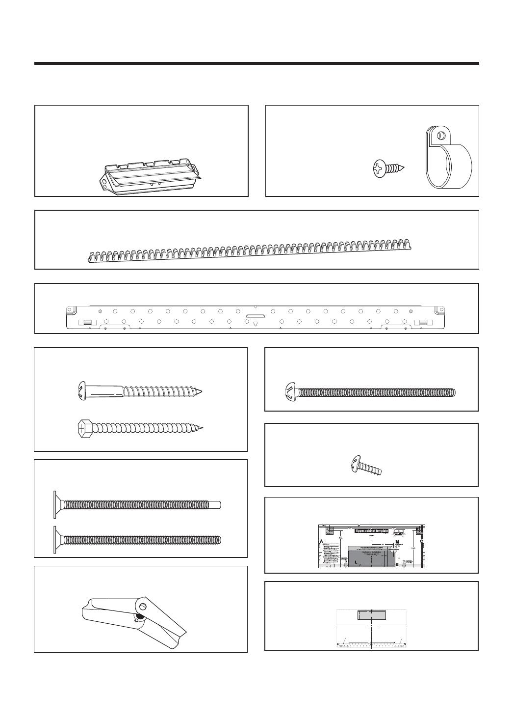
Deux boulons 1/4 x 3 po -
Grandeur réelle
(pour attacher l’armoire supérieure)
Deux vis autotaraudeuses -
Grandeur réelle
(pour attacher le raccord de conduit du clapet de
refoulement)
Un gabarit d’armoire supérieure -
Taille non réelle
Un gabarit de mur arrière - Taille non réelle
(1 pièce de plaque de montage uniquement)
Deux écrous à ailettes -
Grandeur réelle
(pour les boulons à ailettes)
LES PIÈCES SUIVANTES SONT FOURNIES AVEC LE FOUR :
REMARQUE :Les pièces utilisées dépendent des besoins en ventilation; elles ne sont pas nécessairement
toutes utilisées.
Clapet de refoulement / raccord de conduit
(pour les installations à évacuation par le toit ou
le mur).
Taille non réelle (les 2 éléments doivent
être assemblés tel qu’il est indiqué). Non utilisé si
l’évacuation se fait dans la cuisine.
Un serre-câble et
une vis de couleur foncée
(pour retenir le cordon d’alimentation)
Grandeur réelle
Une traversée pour serre-câble - Grandeur réelle
(pour le trou de cordon dans une armoire supérieure en métal)
PIÈCES, OUTILS, MATÉRIAUX
D
4922W5A060E
1.Trim the rear wall template along the dotted line.
2.Center rear wall template in operating by lining up the plumb line on
wall with centerline on template. Then securely tape or tack the rear
wall template in place. Make sure the minimum width is 30 inches and
that the top of the rear wall template is located a minimum of 30 inches
above the cooking surface.
NOTE:If the cabinets are not plumb, adjust the rear wall
template to the cabinets. If the front edge of the
cabinet is lower than the back edge, adjust the
template to be level with the cabinet front.
3.Drill holes at points A,B and C. Drill the fourth hole inside area D, through
one of the bottom holes to match the location of a stud. If there is a stud,
drill a 3/16 hole for lag screws. If there is no stud, drill a 5/8 hole for toggle
bolts.
These holes must be used for mounting. If the holes are not used, the
installation will not be secure. Installer must use these holes for proper
installation.
Use toggle bolts through these holes, unless one of them lines up with a
stud. Use a wood screw for studs.Make sure to use at least 1 lag screw
in stud, and 3 toggle bolts in drywall or the plaster.
NOTE:Cut out the shaded area marked F on the REAR WALL TEMPLATE
for wall-vented.
4. Remove the template from the rear wall
5. RETURN TO AND PROCEED WITH THE INSTALLATION
INSTRUCTIONS.
NOTE: IT IS VERYIMPORTANT TO
READ AND FOLLOW THE DIRECTIONS
IN THE INSTALLATION INSTRUCTIONS
BEFORE PROCEEDING WITH THIS
REAR WALLTEMPLATE.
Printed in China
1/4
12
4
F. CUT OUT FOR WALL
VENTED ONLY
CUT HOLE THROUGH REAR WALL FOR EXHAUST ADAPTOR
REAR WALL TEMPLATE
C
L
30
DERIUQER HTDIW MUMINIM
EDISTUO DENOITISOP SI ROTPADA TSUAHXE FINOITUAC
LLIW RIA NEDAL-ESAERG ,NOISNEMID DEDNEMMOCER
.ERUTCURTS ESUOH OTNI EGRAHCSID
REMARQUE: Il faudra poser au moins un tire-fond dans un montant de 2 x 4 po (51 x 102 mm) et trois
boulons
d’ancrage dans
le mur. La partie portante doit satisfaire aux conditions de capacité
de support de
150 lb
(68 kg) minimum.
Deux tire-fonds de 1/4 x 2 po (6 x 51 mm) -
Deux boulons à ailettes de 1/4 x 3 po (6 x 76 mm) -
Grandeur réelle
Grandeur réelle
(pour les trous dans le placoplâtre)
(pour les trous dans les montants du mur)
Une plaque de montage - Taille non (pour soutenir le four à micro-ondes)
WARNING - TO REDUCE THE RISK OF FIRE AND ELECTRIC SHOCK,
INSTALL AT LEAST 13-3/4 INCHES ABOVE A COOKTOP(OR RANGE)
SUITABLE FOR USE ABOVE GAS OR ELECTRIC
COOKING EQUIPMENT 36 INCHES OR LESS WIDE.
APTO PARA SU USO SOBRE EQUIPOS ELÉCTRICOS O
A GAS CON ANCHO DE 36 PULGADAS (90CM) O INFERIOR
ADVERTENCIA - PARA REDUCIR EL RIESGO DE INCENDIO Y DE DESCARGA ELÉCTRICA,
INSTALE AL MENOS A 13-3/4 PULGADAS (35CM) SOBRE LA VITROCERÁMICA (O FOGÓN)
ou
  • Page 1 1
  • Page 2 2
  • Page 3 3
  • Page 4 4
  • Page 5 5
  • Page 6 6
  • Page 7 7
  • Page 8 8
  • Page 9 9
  • Page 10 10
  • Page 11 11
  • Page 12 12
  • Page 13 13
  • Page 14 14
  • Page 15 15
  • Page 16 16
  • Page 17 17
  • Page 18 18
  • Page 19 19
  • Page 20 20
  • Page 21 21
  • Page 22 22
  • Page 23 23
  • Page 24 24
  • Page 25 25
  • Page 26 26
  • Page 27 27
  • Page 28 28
  • Page 29 29
  • Page 30 30
  • Page 31 31

LG LMV1751ST Mode d'emploi

Catégorie
Micro-ondes
Taper
Mode d'emploi

dans d''autres langues