Gaggenau VG 425 211CA Guide d'installation
- Catégorie
- Cuisinières
- Taper
- Guide d'installation


2
en-us
Table of Contents
Installation instructions
9 Safety Definitions 2
IMPORTANT SAFETY INSTRUCTIONS 3
Appliance Handling Safety 5
Safety Codes and Standards 5
Electric Safety 6
Gas Safety 6
Propane Gas Installation 7
Related Equipment Safety 7
Before You Begin 8
Tools and Parts Needed 8
Parts Included 8
Installation accessories 8
Cabinet Requirements 9
Countertop Requirements 9
Technical Data 9
Prepare Installation Space 10
Cutting out countertop 10
Installation Procedure 12
Mounting Control Knobs 12
Install Appliance 13
Connect Gas Supply 13
Connect Electrical Supply 14
Burner Cap Placement 14
Check the Installation 14
Removing the appliance 14
Conversion to another type of gas 15
Customer Service 17
Additional information on products, accessories,
replacement parts and services can be found at
www.gaggenau.com and in the online shop
www.gaggenau.com/zz/store
9 Safety Definitions
Safety Definitions
9 WARNING
This indicates that death or serious injuries may
occur as a result of non-observance of this
warning.
9 CAUTION
This indicates that minor or moderate injuries may
occur as a result of non-observance of this
warning.
NOTICE
This indicates that damage to the appliance or property
may occur as a result of non-compliance with this
advisory.
Note: This alerts you to important information and/or
tips.

3
9 IMPORTANT SAFETY INSTRUCTIONS
READ AND SAVE THESE INSTRUCTIONS
IMPORTANT SAFETY INSTRUCTIONS
READ AND SAVE THESE INSTRUCTIONSGas Appliance Saf et y
²
'RQRWVWRUHRUXVHJDVROLQHRURWKHUIODPPDEOH
YDSRUVDQGOLTXLGVLQWKHYLFLQLW\RIWKLVRUDQ\
RWKHUDSSOLDQFH
²
:+$772'2,)<2860(//*$6
'RQRWWU\WROLJKWDQ\DSSOLDQFH
'RQRWWRXFKDQ\HOHFWULFDOVZLWFK
'RQRWXVHDQ\SKRQHLQ\RXUEXLOGLQJ
,PPHGLDWHO\FDOO\RXUJDVVXSSOLHUIURPD
QHLJKERU·VSKRQH)ROORZWKHJDVVXSSOLHU·V
LQVWUXFWLRQV
,I\RXFDQQRWUHDFK\RXUJDVVXSSOLHUFDOO
WKHILUHGHSDUWPHQW
²
,QVWDOODWLRQDQGVHUYLFHPXVWEHSHUIRUPHG
E\DTXDOLILHGLQVWDOOHUVHUYLFHDJHQF\RUWKH
JDVVXSSOLHU
,IWKHLQIRUPDWLRQLQWKHVHLQVWUXFWLRQVLVQRW
IROORZHGH[DFWO\DILUHRUH[SORVLRQPD\UHVXOW
FDXVLQJSURSHUW\GDPDJHSHUVRQDOLQMXU\RUGHDWK
:$51,1*

9 IMPORTANT SAFETY INSTRUCTIONS
READ AND SAVE THESE INSTRUCTIONS
4
1HYHU2SHUDWHWKH7RS6XUIDFH&RRNLQJ6HFWLRQRI
WKLV$SSOLDQFH8QDWWHQGHG
)DLOXUHWRIROORZWKLVZDUQLQJVWDWHPHQWFRXOG
UHVXOWLQILUHH[SORVLRQRUEXUQKD]DUGWKDWFRXOG
FDXVHSURSHUW\GDPDJHSHUVRQDOLQMXU\RUGHDWK
,IDILUHVKRXOGRFFXUNHHSDZD\IURPWKHDSSOLDQFH
DQGLPPHGLDWHO\FDOO\RXUILUHGHSDUWPHQW
'2127$77(03772(;7,1*8,6+$12,/*5($6(
),5(:,7+:$7(5
:$51,1*

5
9 IMPORTANT SAFETY INSTRUCTIONS
READ AND SAVE THESE INSTRUCTIONS
IMPORTANT: THE APPLIANCE MUST
BE INSTALLED BY A QUALIFIED
INSTALLER.
INSTALLER: LEAVE THESE
INSTRUCTIONS WITH THE APPLIANCE
AFTER INSTALLATION IS COMPLETE.
IMPORTANT: SAVE FOR THE LOCAL
INSPECTOR’S USE.
9 WARNING
If the information in this manual is
not followed exactly, fire or shock
may result causing property damage
or personal injury.
9 WARNING
Do not repair, replace or remove any
part of the appliance unless
specifically recommended in the
manuals. Improper installation,
service or maintenance can cause
injury or property damage. Refer to
this manual for guidance. All other
servicing should be done by an
authorized service provider.
Improper installation is not covered by
the warranty.
Appliance Handling Safety
Safety Codes and Standards
This appliance complies with one or more
of the following Standards:
▯ UL 858, The Standard for the Safety of
Household Electric Ranges
▯ UL 923, The Standard for the Safety of
Microwave Cooking Appliances
▯ UL 507, The Standard for the Safety of
Electric Fans
▯ ANSI Z21.1 / CSA 1.1 Household Cooking
Gas Appliances
▯ CAN/CSA-C22.2 No. 113-M1984 Fans and
Ventilators
▯ CAN/CSA-C22.2 No. 61-M89 Household
Cooking Ranges
It is the responsibility of the owner and
the installer to determine if additional
requirements and/or standards apply to
specific installations.
Installation must conform with local
codes or, in the absence of local codes,
with the National Fuel Gas Code, ANSI
Z223.1/NFPA 54 or, in Canada, the
Natural Gas and Propane Installation
Code, CSA B149.1.
The appliance must be electrically
grounded in accordance with local codes
or, in the absence of local codes, with the
National Electrical Code, NFPA 70 latest
edition or, in Canada, the Canadian
Electric Code, CSA C22.1-02.
Hidden surfaces may have sharp
edges. Use caution when
reaching behind or under
appliance.

9 IMPORTANT SAFETY INSTRUCTIONS
READ AND SAVE THESE INSTRUCTIONS
6
Electric Safety
9 WARNING
Before you plug in an electrical cord
or turn on power supply, make sure
all controls are in the OFF position.
For appliances equipped with a cord and
plug, do not cut or remove the ground
prong. It must be plugged into a matching
grounding type receptacle to avoid
electrical shock. If there is any doubt as
to whether the wall receptacle is properly
grounded, the customer should have it
checked by a qualified electrician.
Do not use an extension cord.
Do not use an adapter.
If required by the National Electrical
Code (or Canadian Electrical Code), this
appliance must be installed on a separate
branch circuit.
The circuit breaker should have a contact
separation of at least 3 mm on all poles.
Be sure your appliance is properly
installed and grounded by a qualified
technician. Installation, electrical
connections and grounding must comply
with all applicable codes.
Before installing, turn power OFF at the
service panel. Lock service panel to
prevent power from being turned ON
accidentally.
Installer – show the owner the location of
the circuit breaker or fuse. Mark it for
easy reference.
Gas Safety
Install a gas shutoff valve near the
appliance. It must be easily accessible in
an emergency.
Leak testing must be conducted by the
installer according to the instructions in
this manual.
The appliance and its individual shutoff
valve must be disconnected from the gas
supply piping system during any pressure
testing at pressures in excess of ½ psi
(3.5 kPa).
The appliance must be isolated from the
gas supply piping system by closing its
individual manual shutoff valve during any
pressure testing of the gas supply piping
system at test pressures equal to or less
than ½ psi (3.5 kPa).
The minimum supply pressure must be 1"
water column above the manifold
pressure printed on the rating label.
The maximum supply pressure must not
exceed 14.0 inches water column
(34.9 Millibars).
A metal flex line or fixed metal pipe shall
be used to connect gas to the appliance.
If a metal gas line cannot be used,
consult your local certified electrician or
local electric codes for proper grounding.

7
9 IMPORTANT SAFETY INSTRUCTIONS
READ AND SAVE THESE INSTRUCTIONS
IMPORTANT SAFETY NOTICE: Burning
gas cooking fuel generates some by-
products which are on the list of
substances which are known by the State
of California to cause cancer or
reproductive harm. To minimize exposure
to these substances, always operate this
unit according to the instructions
contained in this booklet and provide
good ventilation.
Proposition 65 Warning:
This product may contain a chemical
known to the State of California, which
can cause cancer or reproductive harm.
Therefore, the packaging of your product
may bear the following label as required
by California:
Propane Gas Installation
The propane gas tank must be equipped
with its own high pressure regulator. In
addition, the regulator supplied with this
unit must also be used.
The appliance is shipped from the factory
for use with natural gas. It must be
converted for use with propane. A
qualified technician or installer must do
the conversion.
This appliance has been certified for safe
operation up to a height of 10,000 ft
without any modifications. Exception: For
use with propane the appliance must be
converted per the LP conversion
instructions.
For Massachusetts installations:
▯ Installation must be performed by a
qualified or licensed contractor,
plumber or gas fitter qualified or
licensed by the state, province or
region where this appliance is being
installed.
▯ Shut-off valve must be a “T” handle gas
cock.
▯ Flexible gas connector must not be
longer than 36 inches.
Installer - show the owner where the gas
shut-off valve is located.
Related Equipment Safety
The appliance should only be used if
installed by a qualified technician in
accordance with these installation
instructions. The manufacturer is not
responsible for any damage resulting
from incorrect installation.
Remove all tape and packaging before
using the appliance. Destroy the
packaging after unpacking the appliance.
Never allow children to play with
packaging material.
Never modify or alter the construction of
the appliance. For example, do not
remove leveling legs, panels, wire covers
or anti-tip brackets/screws.
To eliminate the risk of burns or fire by
reaching over heated surface units,
cabinet storage space located above the
surface units should be avoided. If
cabinet storage is to be provided, the risk
can be reduced by installing a hood that
projects horizontally a minimum of 5
&DQFHUDQG5HSURGXFWLYH+DUPZZZ3:DUQLQJVFDJRY
67$7(2)&$/,)251,$352326,7,21:$51,1*
:$51,1*

8
en-us Before You Begin
inches (127 mm) beyond the bottom of the
cabinet.
Verify that cabinets above the cooktop are a
maximum of 13" (330 mm) deep.
When installing a cooktop over a single
oven, be sure to follow both the oven’s and
cooktop’s installation manuals.
Ventilation Recommendations
We strongly recommend the installation of a
ventilation hood above this appliance. The
hood must be installed according to
instructions furnished with the hood.
9 CAUTION
The appliance should not be installed
with a ventilation system that blows air
downward toward the burners. This
type of ventilation system may cause
ignition and combustion problems with
the gas cooking appliance resulting in
personal injury or unintended
operation.
Before You Begin
Before You Begin
Tools and Parts Needed
▯ Screwdriver Torx T20
▯ Pencil
▯ Drill with ¼" (6 mm) bit
▯ Jigsaw
▯ Tape Measure
Note: Additional materials may be necessary for
installation in solid surface countertops. Contact the
countertop manufacturer.
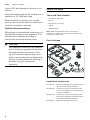
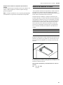
Parts Included
Installation accessories
AA 414 010 Ventilation molding, for operation next to
the VL 414 downdraft ventilation
VA 420 000 Connection strip for combination with
other Vario appliances in the 400 series
for flush installation
VA 420 010 Connection strip for combination with
other Vario appliances in the 400 series
for surface-mounted installation
VA 440 010 Stainless steel appliance cover
[

9
Before You Begin en-us
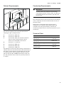
Cabinet Requirements
The minimum spaces that must be maintained when
installing the gas cooktop shall be:
The distance from the top of the cooktop to the bottom of
cabinets above can be reduced to 26" when the bottom of
the wood or metal cabinet is protected by not less than
¼" (6.35 mm)-thick flame-retardant millboard covered
with not less than No. 28 MSG sheet metal, 0.015 inch
(0.4 mm) stainless steel, 0.024 inch (0.6 mm) aluminum
or copper.
Countertop Requirements
9 WARNING
To reduce the risk of ignition of surrounding
combustible materials, install at least 12" (300 mm)
from both sidewalls and at least 2" (50 mm) from
the rear wall.
The countertop must be level and horizontal. The stability
of the countertop must be maintained after the cut-out
has been made.
Solid surface countertops often require special
installations. For example, heat-reflective tape and
rounded corners may be necessary. Contact the
countertop manufacturer for instructions specific to your
countertop.
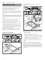
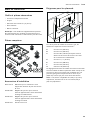
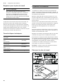
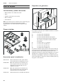
Technical Data
A minimum 12" (300 mm)
B minimum 12" (300 mm)
C minimum 30" (762 mm) clearance between
the top of the cooking surface and the
bottom of combustible constructions
D
minimum 1
9
/
16
" (40 mm)
E minimum 15" (380 mm)
F minimum 18" (457 mm)
G maximum 13" (330 mm)
$
%
)
'
(
&
*
Total connected load electric 25 VA
Total connected load gas
(natural gas)
20,500 BTU/h
(6.0 kW)
Total consumption
(natural gas)
0.530 m³/h
Total connected load gas
(propane gas)
20,500 BTU/h
(6.0 kW)
Total consumption
(propane gas)
430 g/h

10
en-us Prepare Installation Space
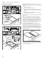
Prepare Installation Space
Prepare Installation Space
The kitchen unit must be heat-resistant to at least
200° F (90°C). The stability of the unit must be
maintained after producing the cut-out.
Produce the cut-out in the countertop for one or more
Vario appliances as shown in the installation sketch. The
angle between the cut surface and the countertop must
be 90°.
The cut edges at the sides must be flat to ensure a good
fit of the retaining springs on the appliance. In laminated
worktops, it may be necessary to fit strips at the sides of
the cut-out.
Remove shavings after cutting. Seal cut surfaces for
resistance to heat and so they are watertight.
Pay attention to a minimum gap of 3/8“ (10 mm) from the
underside of the appliance to kitchen units.
Use suitable base constructions to ensure load-carrying
capacity and stability, especially in the case of thin
countertops. Pay attention to the weight of the appliance,
including any payload. Reinforcement material used must
be resistant to heat and moisture.
Note: Wait until the appliance has been installed in the
installation opening before checking that it is level.
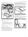
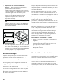
Cutting out countertop
Flush mounting: Flush mounting into a countertop is
possible.
Flush installation: The appliance can be installed in the
following temperature- and water-resistant countertops:
▯ Stone countertops
▯ Plastic countertops (such as Corian®)
▯ Solid wood countertops: Only in consultation with the
manufacturer of the countertop (seal cut-out edges)
▯ Installation in other countertops only in consultation
with the manufacturer of the countertop.
Installation in countertops made of particleboard is not
possible.
Note: Any cut-out work on the countertop must be
performed in a workshop according to the installation
diagram. The cut-out must be made cleanly and precisely
since the cut-out edge is visible on the surface. Clean
and degrease the cut-out edges with a suitable cleaning
agent (bear in mind silicone manufacturer's processing
instructions).
PP
PLQ
PLQ
PLQ
PLQ
PLQ
U
PP
PLQ

11
Prepare Installation Space en-us
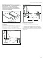
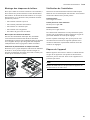
Combining several Vario devices: The connecting strip
VA 420 000/010 is required for the combination of
several Vario appliances. This is available separately as a
special accessory. Consider additional space
requirement for the connecting strip between the
appliances when making the cut-out (see installation
instructions VA 420 000/010).
Appliances can also be installed in individual cut-outs,
bearing in mind a minimum distance between the devices
of 2" (51 mm).
In combination with appliance cover: The appliance cover
VA 440 010 can be ordered separately as an optional
accessory. Take into account the additional space
required for the appliance cover when making the cutout.
Flush mount installation:
Drilled Hole for Control Knob
Possible types of installation:
▯ Installation in the front of the base cabinet
▯ Installation in the countertop next to the appliance
▯ Installation in the countertop in front of the appliance
Note: Follow the installation instructions provided for the
control knobs.
9$
9$
PLQ
9$

12
en-us Installation Procedure
Installation Procedure
Installation Procedure
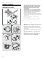
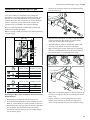
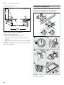
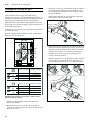
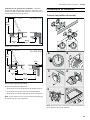
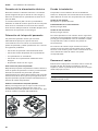
Mounting Control Knobs
Note: Follow the installation instructions provided for the
control knobs.
1. Depending on the distance between the control
knobs, it may be necessary to break off the retaining
plate at the perforation. Hold the retaining plate in
place against the back of the control panel or the
bottom of the countertop, or secure it with the
enclosed screws.
2. When installing a single control knob or when the
retaining plate has been broken at the perforation, use
2 screws to hold each individual retaining plate in
place to prevent it from rotating (C).
For stone countertops, use temperature-resistant two-
component adhesive (for metal to stone) to adhere the
retaining plate.
3. Remove the protective film on the back of the
illuminated ring (A).
4. Insert the control knob into the drilled hole (B) and
screw the nut on the back with the enclosed
installation aid (D).
5. Connect all of the control knobs with the enclosed
shorter cables. The plugs must snap into the sockets
(E).
Note: The two cable connectors on the control knob
are identical.
6. Connect the longer cable to the control cable for
connection to the appliance. The plug must snap into
the socket (F).
Note: The appliance can be connected to any control
knob.
7. After installing, check that all plug connections fit
correctly.
8. After installing all the cables, secure them to the
retaining plate by bending the tab down (E).
$ %
&
'
( )

13
Installation Procedure en-us
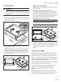
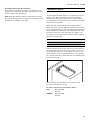
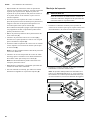
Install Appliance
9 WARNING
Before you plug in an electrical cord or turn on
power supply, make sure all controls are in the OFF
position.
1. Connect the connection cable to the control cable in
the socket on the bottom of the appliance. The plug
must snap into place.
2. Insert appliance evenly into the cutout. Push it down
firmly into the cutout.
Note: The appliance must be firmly fixed in the cutout
and must not be able to move around (e.g., during
cleaning). If the width of the cutout is at the upper
tolerance limit, fasten the ledges at the sides in the
cutout if necessary.
3. Only for flush mount installation:
Note: Make sure that everything is working correctly
before grouting.
Grout the surrounding gap with a suitable
temperature-resistant silicone adhesive. Smooth the
joint seal with a smoothing agent recommended by the
manufacturer. Heed the processing instructions for
the silicone glue. Only start up the appliance after the
silicone glue is completely dry (at least 24 hours,
depending on the room temperature).
NOTICE
Unsuitable silicone adhesive causes permanent
discoloration to natural stone countertops.
4. Connect the appliance to the mains and check that it
works correctly. If the appliance is turned off, air may
be present in the gas line. Turn control knob to 0 and
reignite. Repeat the process until the appliance
ignites.
Connect Gas Supply
The appliance is shipped from the factory for use with
natural gas. It must be converted for use with propane. A
qualified technician or installer must do the conversion.
Before connecting the appliance, please check whether
the local connection conditions such as gas type and gas
pressure match the appliance settings.
Make sure the gas supply is turned off at the manual shut-
off valve before connecting the appliance.
The gas connection must be in a location that permits
access to the manual shut-off valve and which, if
applicable, is visible after opening the door of the
cabinet.
The flexible gas line must not come into contact with
moving parts of the fitted unit (e.g. drawers) or be laid in
areas where it could become trapped or damaged.

14
en-us Installation Procedure
The flexible gas line must not come into contact with a
cooktop, oven, dishwasher, refrigerator, washing
machine, hot water pipe, radiator or any other appliance
installed in the vicinity of the gas cooktop.
The flexible gas line must not be subject to rubbing,
vibrations, kinking or any other kind of deformation. It
should be checked along its entire length with the
cooktop in the installation position.
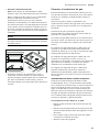
SERVICER INFO ONLY
Connect the gas supply using the ½" U.S.A. elbow and
the fiber gasket supplied with the unit. The shorter,
nontapered thread fits into the threaded nut on the hob.
The longer, tapered U.S.A. thread is for the incoming gas
supply. Vent the gas line, check for leaks. The gas
pressure regulator is supplied with the unit and comes
set for natural gas. To convert regulator to LP (propane)
gas:
Make-Maxitrol Model RV 47 CL ½ PSIG
1. Remove the aluminum cap from the top of the
regulator.
2. Remove the yellow plastic shaft from the cap by
pushing it sideways until it pops out of the groove in
the cap.
3. Turn the shaft over and push back into the cutout in
the cap.
4. Replace the cap on the regulator.
Connect Electrical Supply
Before connecting supply cord to wall receptacle, make
certain that gas shutoff valve and all burner controls are
in OFF position.
Electrical connection (AC 110-127 V) is established by
means of a connecting cord with a grounding contact
plug connected to a grounded socket, which must also
be accessible after installation of the gas cooktop.
Burner Cap Placement
The burner parts must be properly placed for the cooktop
to function properly. If the burner parts are not properly
placed, one or more of the following problems may occur:
▯ Burner flames are too high.
▯ Flames shoot out of burners.
▯ Burners do not ignite.
▯ Burner flames light unevenly.
▯ Burner emits gas odor.
Placing Burner Parts
After electrical connection is complete, assemble the
burner parts correctly and evenly. When assembling the
burner parts, make sure that the burner head is placed on
the base in such a way that the prongs of the burner cap
fit snugly into the groove of the burner base.
Checking Burner Cap Placement
Check to make sure that there is no gap between the
burner parts. You may gently try to move the burner parts
from side to side to check if they are properly placed.
Check the Installation
Check operation of electric igniters. Check flame
characteristics. Flame should be blue with no yellow tip.
Yellow Flames:
Further adjustment is required.
Yellow Tips on Outer Cones:
Normal for LPG Gas.
Soft Blue Flames:
Normal for Natural Gas.
If the flame is completely or mostly yellow, verify that the
regulator is set for the correct fuel. After adjustment,
retest.
Some yellow streaking is normal during the initial start-
up. Allow unit to operate 4-5 minutes and re-evaluate
before making adjustments.
Removing the appliance
Disconnect the appliance from the power supply. Close
the gas shut-off valve. Remove the silicone joint from
appliances installed flush. Push out the appliance from
below.
NOTICE
Appliance damage! Do not lever out the appliance at the
frame from above.

15
Conversion to another type of gas en-us
Conversion to another type of gas
Conversion to another type of gas
This gas stovetop corresponds to the categories
specified on the rating plate. By changing nozzles, it is
possible to convert the appliance to any of the gases
listed on the plate. The conversion kit can be obtained
from our customer service. With some models, the
conversion kit is included in the scope of delivery.
Only a licensed specialist is authorized to switch the
appliance to another gas type.
Before carrying out the conversion, turn off the electricity
and gas supply.
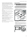
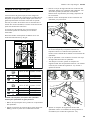
Replacing the Main Control Nozzles: Normal and High
Output Burners
1. Remove the pan supports and all burner parts.
2. Unscrew the fastening nuts from the cooktop (3 nuts –
WAF 7), and carefully lift up the cooktop to remove it.
3. Remove the securing clips from the burner pipes. Pull
out the burner pipes. The electrode can remain
connected. Unscrew the burners (Torx T20) and pull
out the burner pipes.
4. Remove the nozzles from the burner pipes by hand,
pull off the O-ring.
5. Check that the O-ring fits correctly in the new main
control nozzle. Pull the nozzles off of the burner
pipes. Do not bend the burner pipes!
6. Attach the burner pipes to the burners. Attach the
securing clips. Screw the burners into place.
7. After loosening the screw, adjust the air regulating
sleeve for the external burner to the correct setting
(see nozzle table – L1). Retighten the screw.
8. Adjust the air regulating sleeve for the inner burner by
turning or sliding it to the correct setting (see nozzle
table – L2).
9. Put the cooktop in place and tighten the screws
evenly. Put the burner parts and pan supports in
place, and ensure that they are positioned correctly.
D
D
$
&
F
F
&
$
1*$:&
3URSDQH:&
RSHQ
1*$:&
3URSDQH:&
RSHQ
D
/
D
/
F
/
F
/
PP
PP
ç¼ȭȬPP
Ȣ¼ȭȬPP
Ȣ¼ȭȬPP
éPP
/
23(1 PP PP
/

16
en-us Conversion to another type of gas
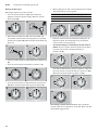
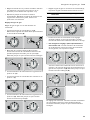
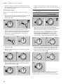
Setting the Gas Type
Set the gas type via any control knob:
1. Turn the control knob to 0 (A). Disconnect the
appliance from the power supply. Wait for at least
30 seconds (B).
2. Reconnect the appliance (C). The illuminated ring
around the control knob will turn green for a second
and then turn yellow (D). Wait until the illuminated ring
goes out.
3. Turn the control knob counterclockwise to position 12
(E).
4. Turn the control knob clockwise to position 1 (F).
5. Turn the control knob counterclockwise to position 0
(G). Wait until the illuminated ring turns yellow (H).
6. Set the gas type on the control knob (I), the currently
selected position will turn green:
7. Keep the control knob at the desired setting for at
least 5 seconds. The illuminated ring around the
control knob will turn green (I).
8. To save the setting, it is necessary to exit the menu as
follows: Turn the control knob to position 0 (J). Then
turn the control knob counterclockwise to
position 12 (K).
Turn the control knob clockwise to position 1 (L). Turn
the control knob counterclockwise to position 0 (M).
Wait until the illuminated ring goes out (N).
The setting is saved. The illuminated ring around the
control knob will turn yellow for a second. Wait until the
illuminated ring goes out.
V
$%
&
'
)
(
)
*+
Control knob position Gas Type
7 NG A 6" WC
9 Propane 10" WC
3URSDQH:&
1*$:&
V
,
.-
1
0/

17
Customer Service en-us
Checking functions after the conversion:
The flames are adjusted correctly if no yellow tips are
visible. They must not go out when switching over swiftly
from the high to the low setting.
Note: Stick the adhesive label included with the nozzle
set over the rating plate of the appliance to document the
changeover to a different gas type.
Customer Service
Customer Service
If your appliance needs repairs, our customer service is
there for you. We work hard to help solve problems
quickly and without unnecessary service calls, getting
your appliance back up and running correctly in the least
amount of time possible.
When you call, please indicate the product number
(E-Nr.) and serial number (FD-Nr.) so that we can support
you in a qualified manner. You will find the type plate with
these numbers on the bottom of the appliance. To avoid
having to search for a long time when you need it, you
can enter your appliance data and the customer support
telephone number here.
Please read the use and care instructions provided with
your appliance. Failure to do so may result in an error in
using the appliance. This could result in a service call
that instead of fixing a mechanical issue is only needed
for customer education. Such calls are not covered by the
appliance warranty.
Please find the contact data of all countries in the
enclosed customer service list.
To book a service visit and product advice
E-Nr. FD-Nr.
Customer Service O
USA 877 442 4436
toll-free
CANADA 877 442 4436
toll-free

18
fr-ca
Table des matières
Notice de montage
9 Définitions de sécurité 18
CONSIGNES DE SÉCURITÉ IMPORTANTES 19
Sécurité de manutention des appareils 21
Codes et normes de sécurité 21
Sécurité électrique 22
Sécurité en matière de gaz 22
Installation au gaz propane 23
Équipement de sécurité 24
Avant de commencer 25
Outils et pièces nécessaires 25
Pièces comprises 25
Accessoires d'installation 25
Exigences pour les placards 25
Exigences pour le plan de travail 26
Caractéristiques techniques 26
Préparation des meubles 26
Découper le plan de travail 26
Procédure d'installation 28
Monter les boutons de commande 28
Pose de l'appareil 29
Branchement du gaz 30
Brancher l'alimentation électrique 30
Montage des chapeaux de brûleur 31
Vérification de l'installation 31
Dépose de l'appareil 31
Changement de type de gaz 32
Service après-vente 34
Vous trouverez des informations supplémentaires
concernant les produits, accessoires, pièces de
rechange et services sur Internet sous :
www.gaggenau.com et la boutique en ligne :
www.gaggenau.com/zz/store
9 Définitions de sécurité
Définitions de sécuri té
9 AVERTISSEMENT
Ceci indique que le non-respect de cet
avertissement peut entraîner des blessures graves,
voire la mort.
9 ATTENTION
Ceci indique que le non-respect de cet
avertissement peut entraîner des blessures légères
ou de gravité moyenne.
AVIS
Ceci indique que la non-conformité à cet avis de sécurité
peut entraîner des dégâts matériels ou endommager
l'appareil.
Remarque : Ceci vous signale des informations et/ou
indications importantes.

19
9 CONSIGNES DE SÉCURITÉ IMPORTANTES
LIRE ET CONSERVER CES INSTRUCTIONS
CONSIGNES DE SÉCURITÉ IMPORTANTES
LIRE ET CONSERVER CES INSTRUCTIONSSé c u r i t é en mat i èr e de gaz
²
1HSDVFRQVHUYHURXXWLOLVHUGHOHVVHQFHRX
GDXWUHVOLTXLGHVRXYDSHXUVLQIODPPDEOHVj
SUR[LPLWpGHFHWDSSDUHLORXGHWRXWDXWUHDSSDUHLO
²
48()$,5(6,92863(5&(9(=81(2'(85'(*$=
1HSDVHVVD\HUGHPHWWUHXQDSSDUHLOVRXVWHQVLRQ
1HSDVWRXFKHUGLQWHUUXSWHXUGHFRXUDQWpOHFWULTXH
1HSDVXWLOLVHUGHWpOpSKRQHVGDQVOpGLILFH
&RPPXQLTXHULPPpGLDWHPHQWDYHFOHIRXUQLVVHXU
GHJD]GHSXLVODSSDUHLOWpOpSKRQLTXHGXQYRLVLQ
5HVSHFWHUOHVGLUHFWLYHVGXIRXUQLVVHXUGHJD]
6LOVDYqUHLPSRVVLEOHGHMRLQGUHOHIRXUQLVVHXUGH
JD]FRPPXQLTXHUDYHFOHVSRPSLHUV
²
8WLOLVHUOHVVHUYLFHVGXQLQVWDOODWHXURXGXQHDJHQFH
GHVHUYLFHVTXDOLILpVRXOHIRXUQLVVHXUGHJD]SRXU
SURFpGHUjOLQVWDOODWLRQHWDX[UpSDUDWLRQV
6LOHVGLUHFWLYHVQHVRQWSDVVXLYLHVjODOHWWUH
LO\DXQULVTXHGLQFHQGLHRXGH[SORVLRQSRXYDQW
HQWUDvQHUGHVGRPPDJHVPDWpULDX[GHVEOHVVXUHV
RXXQGpFqV
$9(57,66(0(17

9 CONSIGNES DE SÉCURITÉ IMPORTANTES
LIRE ET CONSERVER CES INSTRUCTIONS
20
1HIDLWHVMDPDLVIRQFWLRQQHUODVXUIDFHGHFXLVVRQVXU
OHGHVVXVGHFHWDSSDUHLOVDQVVXUYHLOODQFH
/HQRQUHVSHFWGHFHWWHPLVHHQJDUGHSRXUUDLW
HQWUDvQHUXQLQFHQGLHXQHH[SORVLRQRXXQULVTXH
GHEUOXUHHWDLQVLFDXVHUGHVGRPPDJHVPDWpULHOV
GHVEOHVVXUHVRXODPRUW
6LO·DSSDUHLOSUHQGIHXWHQH]YRXVjO·pFDUWHW
DSSHOH]LPPpGLDWHPHQWYRWUHVHUYLFHGHVLQFHQGLHV
1(7(17(=-$0$,6'·e7(,1'5(81)(8'(*5$,66(
28'·+8,/((1/·$63(5*($17'·($8
$9(57,66(0(17
La page est en cours de chargement...
La page est en cours de chargement...
La page est en cours de chargement...
La page est en cours de chargement...
La page est en cours de chargement...
La page est en cours de chargement...
La page est en cours de chargement...
La page est en cours de chargement...
La page est en cours de chargement...
La page est en cours de chargement...
La page est en cours de chargement...
La page est en cours de chargement...
La page est en cours de chargement...
La page est en cours de chargement...
La page est en cours de chargement...
La page est en cours de chargement...
La page est en cours de chargement...
La page est en cours de chargement...
La page est en cours de chargement...
La page est en cours de chargement...
La page est en cours de chargement...
La page est en cours de chargement...
La page est en cours de chargement...
La page est en cours de chargement...
La page est en cours de chargement...
La page est en cours de chargement...
La page est en cours de chargement...
La page est en cours de chargement...
La page est en cours de chargement...
La page est en cours de chargement...
La page est en cours de chargement...
La page est en cours de chargement...
La page est en cours de chargement...
La page est en cours de chargement...
La page est en cours de chargement...
La page est en cours de chargement...
-
 1
1
-
 2
2
-
 3
3
-
 4
4
-
 5
5
-
 6
6
-
 7
7
-
 8
8
-
 9
9
-
 10
10
-
 11
11
-
 12
12
-
 13
13
-
 14
14
-
 15
15
-
 16
16
-
 17
17
-
 18
18
-
 19
19
-
 20
20
-
 21
21
-
 22
22
-
 23
23
-
 24
24
-
 25
25
-
 26
26
-
 27
27
-
 28
28
-
 29
29
-
 30
30
-
 31
31
-
 32
32
-
 33
33
-
 34
34
-
 35
35
-
 36
36
-
 37
37
-
 38
38
-
 39
39
-
 40
40
-
 41
41
-
 42
42
-
 43
43
-
 44
44
-
 45
45
-
 46
46
-
 47
47
-
 48
48
-
 49
49
-
 50
50
-
 51
51
-
 52
52
-
 53
53
-
 54
54
-
 55
55
-
 56
56


Gaggenau VG 425 211CA Guide d'installation
- Catégorie
- Cuisinières
- Taper
- Guide d'installation
dans d''autres langues
- English: Gaggenau VG 425 211CA Installation guide
- español: Gaggenau VG 425 211CA Guía de instalación
- português: Gaggenau VG 425 211CA Guia de instalação
Documents connexes
-
Gaggenau VG425211CA Guide d'installation
-
-
Gaggenau VG415211CA Guide d'installation
-
Gaggenau VG231220CA Guide d'installation
-
Gaggenau VG264220CA Guide d'installation
-
Gaggenau VG232220CA Guide d'installation
-
Gaggenau VG 295 150CA Guide d'installation
-
Gaggenau VG 295 Guide d'installation
-
Gaggenau VK414610 Guide d'installation
-
Gaggenau VR 414 611 Guide d'installation
Autres documents
-
Bosch NGMP677UC Guide d'installation
-
Bosch NGMP077UC Manuel utilisateur
-
Bosch Benchmark NGMP677UC Guide d'installation
-
-
Bosch Benchmark NGMP077UC Guide d'installation
-
 Gaggenau USA VG295214CA Guide d'installation
-
Bosch NGM8657UC Le manuel du propriétaire
-
Gaggenau Deals VE260614 Guide d'installation
