Danby DAS120GBHWDB Le manuel du propriétaire
- Catégorie
- Climatiseurs split-system
- Taper
- Le manuel du propriétaire
Ce manuel convient également à

DANBY PRODUCTS LIMITED, ONTARIO, CANADA N1H 6Z9
DANBY PRODUCTS INC., FINDLAY, OHIO, USA 45840
www.Danby.com
*
*
INSTALLATION MANUAL
MANUEL D'INSTALLATION
MANUAL DE INSTALACIÓN
2020.12.16
FOR ANY QUESTIONS OR CONCERNS REGARDING INSTALLATION OR SERVICING OF THIS UNIT,
PLEASE CONTACT THE DEALER OR BUILDER WHO SOLD THE UNIT.
_____________________________________________________________________
POUR TOUTE QUESTION OU PRÉOCCUPATION CONCERNANT L’INSTALLATION OU L’ENTRETIEN
DE CET APPAREIL, VEUILLEZ CONTACTER LE REVENDEUR OU LE CONSTRUCTEUR QUI A VENDU
L’APPAREIL.
__________________________________________________________________
PARA CUALQUIER PREGUNTA O INQUIETUD RELACIONADA CON LA INSTALACIÓN O SERVICIO DE
ESTA UNIDAD, PÓNGASE EN CONTACTO CON EL DISTRIBUIDOR O CONSTRUCTOR QUE VENDIÓ LA
UNIDAD.
SPLIT AIR CONDITIONER
Installation Guide ............................................... 1 - 26
CLIMATISEUR DIVISÉ
Guide d’installation........................................... 27 - 52
AIRE ACONDICIONADO DIVIDIDO
Guía de instalación............................................ 53 - 78
MODEL • MODÈLE • MODELO
DAS120GBHWDB
DAS170GBHWDB
DAS220GBHWDB

1
SAVE THESE INSTRUCTIONS!
Important Safety Information
READ AND FOLLOW ALL SAFETY INSTRUCTIONS
SAFETY PRECAUTIONS
Incorrect installation due to ignoring instructions
can cause serious damage or injury.
• When connecting refrigerant piping, do not let
substances or gases other than the specifi ed
refrigerant enter the lines as this will lower the
unit’s capacity and can cause abnormally high
pressure in the refrigeration system, which can
lead to explosion or injury.
• Installation must be performed by a certifi ed
HVAC technician. Defective installation can
cause water leakage, electrical shock or fi re.
• In North America, installation must be
performed in accordance with the requirement
of NEC and CEC by authorized personnel only.
• Contact an HVAC technician or the sales agent
for information on repair or maintenance of this
appliance.
• Only use the included accessories, parts and
specifi ed parts for installation. Using non-
standard parts can cause water leakage,
electrical shock, fi re and can cause the unit to
fail.
• Install the appliance in a fi rm location that can
support the unit’s weight. If the chosen location
cannot support the appliance’s weight, or if
the installation is not completed properly, the
appliance may fall and cause serious injury or
damage.
• For all electrical work, follow all local and
national wiring standards and regulations and
this manual. You must use an independent
circuit and single outlet to supply power. Do not
connect other appliances to the same outlet.
Insuffi cient electrical capacity or defects in
electrical work can cause electrical shock or fi re.
• For all electrical work, use all specifi ed cables.
Connect cables tightly and clamp them securely
to prevent external forces from damaging the
terminal. Improper electrical connections can
overheat and cause electrical shock or fi re.
• All wiring must be correctly arranged to ensure
that the control board can close properly. If the
control board cover is not closed properly, it
can lead to corrosion and cause the connection
points on the terminal to overheat, catch fi re or
cause electrical shock.
• In certain functional environments, such as
kitchens, server rooms, etc., the use of specially
designed air conditioning units is highly
recommended.
• This appliance is not intended for use by persons
(including children) whose physical, sensory or
metal capabilities may be different or reduced,
or who lack experience or knowledge, unless
such persons receive supervision or training to
operate the appliance by a person responsible
for their safety.
• Do not install the appliance in a location that
may be exposed to combustible gas leaks.
If combustible gas accumulates around the
appliance, it may cause fi re.
• Do not operate this appliance in a wet room
such as a bathroom or laundry room. Too
much exposure to water can cause electrical
components to short circuit.
• The appliance must be properly grounded or
electric shock can occur.
• Install drainage piping according to the
instructions in this manual. Improper drainage
may cause water damage.
NOTE ABOUT FLUORINATED GASES
• This appliance contains fl uorinated gasses. For
specifi c information on the type and amount of
gas, refer to the relevant label on the appliance
itself.
• Installation, service, maintenance and repair of
this appliance must be performed by a certifi ed
HVAC technician.
• Uninstallation and recycling must be performed
by a certifi ed HVAC technician.
• If the appliance has a leak detection system
installed, it must be checked for leaks at least
every 12 months. When the appliance is
checked for leaks, proper record keeping of all
checks is strongly recommended.

2
INSTALLATION INSTRUCTIONS
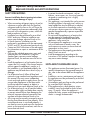
ACCESSORIES
1. Mounting plate (x2)
2. Mounting plate fi xing screw ST3.9 x 25 (x10)
3. Clip anchor (x10)
4. Remote control (x2)
5. Dry battery AAA.LR03 (x4)
6. Drain joint
7. Tie
8. Putty
9. Wear protective ring wall
10. Power line
11. Drain pipe
12. Connecting pipe
13. Remote control stand
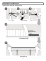
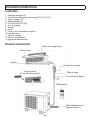
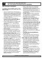
INSTALLATION SUMMARY
Front Panel
Louver
Drainage Pipe
Signal Cable
Refrigerant Pipe
Remote Control
Outdoor Unit
Power Cable
Functional Filter
On Front of Main Filter
Wall Mounting Plate

3
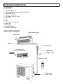
INSTALLATION INSTRUCTIONS
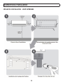
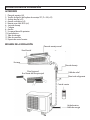
INSTALLATION SUMMARY - INDOOR UNIT

4
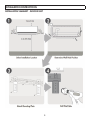
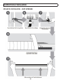
INSTALLATION INSTRUCTIONS
INSTALLATION SUMMARY - INDOOR UNIT
L1 L2 S

5
INSTALLATION INSTRUCTIONS
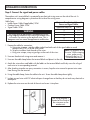
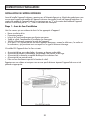
INDOOR UNIT INSTALLATION
Before installing the indoor unit, refer to the label on the product box to ensure that the model number on
the indoor unit matches the model number on the outdoor unit. The indoor unit model number will end with
a “-I” and the outdoor unit model number will end with a “-O”, otherwise they should be identical.
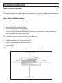
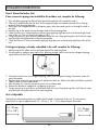
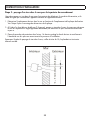
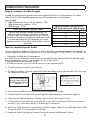
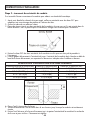
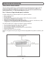
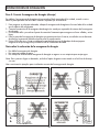
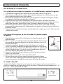
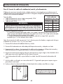
Step 1: Select Installation Location
Proper installation locations meet the following standards:
• Good air circulation.
• Convenient drainage.
• Noise from the unit will not be disturbing.
• Firm and solid location that will not vibrate.
• Strong enough to support the weight of the unit.
• At least 1 m (3 feet) away from all other electrical devices, such as televisions, radios and computers,
which could impact the infrared remote signal.
Do not install the indoor unit in locations that have the following:
• Near any source of heat, steam or combustible gas.
• Near fl ammable items such as curtains or clothing.
• Near any obstacle that might block air circulation.
• Near any doorway.
• In direct sunlight.
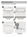
Refer to the below illustration to ensure proper distance from surrounding walls and ceiling:

6
INSTALLATION INSTRUCTIONS
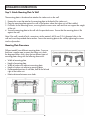
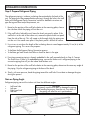
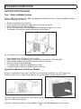
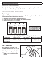
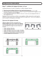
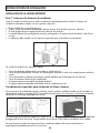
Step 2: Attach Mounting Plate To Wall
The mounting plate is the device that attaches the indoor unit on the wall.
1. Remove the screw that attaches the mounting plate to the back of the indoor unit.
2. Place the mounting plate against the wall in the location where the indoor unit will be installed.
3. Drill holes for the mounting screws, ensuring that the screws enter wall studs that can support the weight
of the unit.
4. Secure the mounting plate to the wall with the provided screws. Ensure that the mounting plate is fl at
against the wall.
Note: If the wall is made of brick, concrete or similar material, drill 5 mm (0.2 in) diameter holes in the
wall and insert the provided sleeve anchors. Secure the mounting plate to the wall by tightening the screws
into the clip anchors.
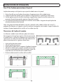
Mounting Plate Dimensions
Different models have different mounting plates. To ensure
that there is ample room to mount the indoor unit, check
the diagrams below which show the two different types of
mounting plates along with the following dimensions:
• Width of mounting plate.
• Height of mounting plate.
• Width of indoor unit relative to mounting plate.
• Height of indoor unit relative to mounting plate.
• Recommended position of wall hole, both to the left and
right of the indoor unit.
• Relative distance between screw holes.

7
INSTALLATION INSTRUCTIONS
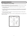
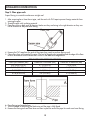
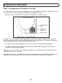
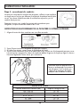
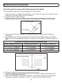
Step 3: Drill Wall Hole For Connective Piping
A hole must be drilled through the wall to the outside to accommodate the refrigerant piping, the drainage
pipe and the signal cable that will connect the indoor and outdoor units.
1. Determine the location of the wall hole based on the position of the mounting plate. See Step 2 for
mounting plate dimensions.
2. The wall hole should have a 65 mm (2.5 in) diameter and it should be drilled on a downward angle to
facilitate drainage. The outdoor end of the hole should be lower than the indoor end of the hole by 5 -
7 mm (0.2 - 0.275 in).
3. Place the protective wall cuff in the hole. This will protect the edges of the hole and will help seal the
hole once the installation is complete.
Note: When drilling the wall hole, make sure to avoid wires, plumbing and other sensitive components that
could be within the wall.

8
INSTALLATION INSTRUCTIONS
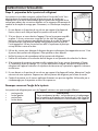
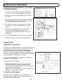
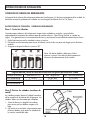
Step 4: Prepare Refrigerant Piping
The refrigerant piping is inside an insulating sleeve attached to the back of the
unit. The piping must be prepared before passing it through the hole in the wall.
Refer to the Refrigerant Piping Connection section for detailed instructions on
pipe fl aring and fl are torque requirements, etc.
1. Based on the position of the wall hole relative to the mounting plate, choose
the side from which the piping will exit the unit.
2. If the wall hole is behind the unit, leave the knock out panel in place. If the
wall hole is to the side of the indoor unit, remove the plastic knock out panel
from the side of the unit. This will create a slot through which the piping can
exit the unit. Use needle nose pliers if the plastic panel is diffi cult to remove.
Knock out panel
3. Use scissors to cut down the length of the insulating sleeve to reveal approximately 15 cm (6 in) of the
refrigerant piping. This serves two purposes:
• To facilitate the Refrigerant Piping Connection process
• To facilitate gas leaks checks and allow a check for dents in the pipe
4. If existing connective piping is already embedded in the wall, proceed directly to Step 5: Connect
The Drain Hose. If there is no embedded piping, connect the indoor unit’s refrigerant piping to the
connective piping that will join the indoor and outdoor units.
5. Based on the position of the wall hole relative to the mounting plate, determine the necessary angle of
the piping. Grip the refrigerant piping at the base of the bend.
6. Slowly, with even pressure, bend the piping toward the wall hole. Do not dent or damage the pipe
during the process.
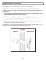
Note on Piping Angle
Refrigerant piping can exit the indoor unit from four different angles:
• Left-hand side
• Left rear
• Right-hand side
• Left rear
CAUTION
Be extremely careful not to dent or damage the piping
while bending them away from the unit. Any dents in
the piping will affect the unit’s performance.

9
INSTALLATION INSTRUCTIONS
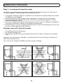
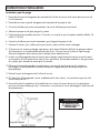
Step 5: Connect the Drain Hose
By default, the drain hose is attached to the left-hand side of the unit, when facing the back of the unit. It
can also be attached to the right-hand side.
1. To ensure proper drainage, attach the drain hose on the same side of the unit as the refrigerant piping.
2. Attach the drain hose extension (purchased separately) to the end of the drain hose.
3. Wrap the connection point fi rmly with Tefl on tape to ensure a good seal and prevent leaks.
4. For the portion of the drain hose that will remain indoors, wrap it with foam pipe insulation to prevent
condensation.
5. Remove the air fi lter and pour a small amount of water into the drain pan to make sure that water fl ows
from the unit smoothly.
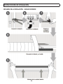
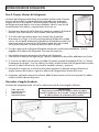
Note on Drain Hose Placement
• Do not kink the drain hose.
• Do not create a water trap.
• Do not put the end of the drain hose in water or a container that will collect water.
Note: To prevent unwanted leaks, plug the unused drain hole with the provided rubber plug.
See below for examples of correct drain hose installation:

10
INSTALLATION INSTRUCTIONS
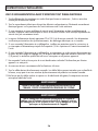
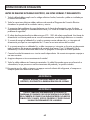
BEFORE PERFORMING ELECTRICAL WORK, READ THESE REGULATIONS
1. All wiring must comply with local and national electrical codes and must be installed by a licensed
electrician.
2. All electrical connections must be made according to the Electrical Connection Diagram located on the
panels of the indoor and outdoor units.
3. If there is a serious safety issue with the power supply, stop work immediately. Explain your reasoning
to the client and refuse to install the unit until the safety issue is resolved.
4. Power voltage should be within 90 - 100% of rated voltage. Insuffi cient power supply can cause
malfunction, electrical shock or fi re.
5. If connecting power to fi xed wiring, install a surge protector and main power switch with a capacity of
1.5 times the maximum current of the unit.
6. If connecting power to fi xed wiring, a switch or circuit breaker that disconnects all poles and has a
contact separation of at least 3 mm (1.8 in) must be incorporated in the fi xed wiring. The qualifi ed
technician must use an approved circuit breaker or switch.
7. Only connect the unit to an individual branch circuit outlet. Do not connect another appliance to that
outlet.
8. Make sure to properly ground the appliance.
9. Every wire must be fi rmly connected. Loose wiring can cause the terminal to overheat, resulting in
product malfunction and possible fi re.
10. Do not let wires touch or rest against the refrigerant tubing, the compressor or any moving parts within
the unit.
WARNING
BEFORE PERFORMING ANY ELECTRICAL WIRING WORK,
TURN OFF THE MAIN POWER TO THE SYSTEM.
WARNING
All wiring must be performed in accordance with the wiring
diagram located on the inside of the indoor unit’s wire cover.
Do not mix up live and null wires. This is dangerous and can
cause the appliance to malfunction.

11
INSTALLATION INSTRUCTIONS
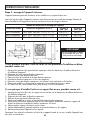
Step 6: Connect the Signal Cable
The signal cable enables communication between the indoor and outdoor units. You must fi rst choose the
right cable size before preparing it for connection.
Cable types:
• Indoor Power Cable (if applicable): SOW
• Outdoor Power Cable: SOW
• Signal Cable: SOW
Minimum Cross Sectional Area of
Power and Signal Cables
Appliance Amps (A) AWG
10 18
13 16
18 14
25 12
30 10
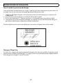
CHOOSE THE RIGHT SIZE CABLE
The size of the power supply cable, signal cable, fuse and
switch needed is determined by the maximum current in the
unit. The maximum current is indicated on the rating plate
located on the side panel of the unit. Refer to this rating plate to
choose the right cable, fuse and switch.
Take Note of Fuse Specifi cations
The air conditioner circuit board (PCB) is designed with a fuse to provide over current protection. The
specifi cations of the fuse are printed on the circuit board, such as: T3.15A/250VAC, T5A/250VAC, etc.
1. Prepare the cable for connection:
a. Using wire strippers, strip the rubber jacket from both ends of the signal cable to reveal
about 40 mm (1.57 in) of the wires inside.
b. Strip the insulation from the ends of the wires.
c. Using wire crimper, crimp u-type lugs on the ends of the wires.
2. Open the front panel of the indoor unit.
3. Using a screwdriver, open the wire box cover on the right side of the unit. This will reveal the terminal
block.
4. Unscrew the cable clamp below the terminal block and place it to the side.
5. Facing the back of the unit, remove the plastic panel on the bottom left-hand side.
6. Feed the signal wire through this slot, from the back of the unit to the front.
7. Facing the front of the unit, match the wire colours with the labels on the terminal block, connect the
u-lug and fi rmly screw each wire to its corresponding terminal.
8. After checking to make sure every connection is secure, use the cable clamp to fasten the signal cable
to the unit. Screw the cable clamp down tightly.
9. Replace the wire cover on the front of the unit and the plastic panel on the back.
The wiring diagram is
located on the inside of
the wire cover on the
indoor unit.
Note: Pay attention to the live
wire. While crimping wires,
make sure to distinguish the Live
(“L”) Wire and other wires.

12
INSTALLATION INSTRUCTIONS
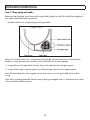
Step 7: Wrap piping and cables
Before passing the piping, drain hose and the signal cable through the wall hole, bundle them together to
save space, protect them and insulate them.
1. Bundle the drain hose, refrigerant pipes and signal cable.
Note: Ensure that the drain hose is at the bottom of the bundle. Putting the drain hose at the top of the
bundle can cause the drain pan to overfl ow, which can lead to fi re or water damage.
2. Using adhesive vinyl tape, attach the drain hose to the underside of the refrigerant pipes.
3. Using insulation tape, wrap the signal wire, refrigerant pipes and drain hose tightly together.
Note: While bundling these items together, do not intertwine or cross the signal cable with any other
wiring.
Note: When wrapping the bundle, keep the ends of piping unwrapped. Access is required to test for leaks
at the end of the installation process.

INSTALLATION INSTRUCTIONS
13
Step 8: Mount the Indoor Unit
If new connective piping was installed to the outdoor unit, complete the following:
1. If the refrigerant piping has already been passed through the wall, proceed to step 4.
2. Otherwise, double check that the ends of the refrigerant pipes are sealed to prevent dirt or foreign
materials from entering the pipes.
3. Slowly pass the wrapped bundle of refrigerant pipes, drain hose and signal wire through the hole in
the wall.
4. Hook the top of the indoor unit on the upper hook of the mounting plate.
5. Check that the unit is hooked fi rmly on mounting by applying slight pressure to the left and right-hand
sides of the unit. The unit should not jiggle or shift.
6. Using even pressure, push down on the bottom half of the unit. Keep pushing down until the unit snaps
onto the hooks along the bottom of the mounting plate.
7. Check that the unit is fi rmly mounted by applying slight pressure to the left and right-hand sides of the
unit.
If refrigerant piping is already embedded in the wall, complete the following:
1. Hook the top of the indoor unit on the upper hook of the mounting plate.
2. Use a bracket or wedge to prop up the unit, allowing enough room to connect the refrigerant piping,
signal cable and drain hose.
3. Connect the drain hose and refrigerant piping. Refer to the Refrigerant Piping Connection section for
more information.
4. Keep the pipe connection point exposed to perform the leak test. Refer to the Electrical Checks and Leak
Checks section for more information.
5. After the leak test, wrap the connection point with insulation tape.
6. Remove the bracket or wedge that is propping up the unit.
7. Using even pressure, push down on the bottom half of the unit. Keep pushing down until the unit snaps
onto the hooks along the bottom of the mounting plate.
Unit is Adjustable
The hooks on the mounting plate are smaller than the holes on the back of the unit. The unit can be
adjusted left or right by approximately 30 - 50 mm (1.25 - 1.95 in) depending on the model.
10 - 20 mm
( 0.4 - 0.8”)
10 - 20 mm
( 0.4 - 0.8”)

14
INSTALLATION INSTRUCTIONS
OUTDOOR UNIT INSTALLATION
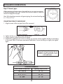
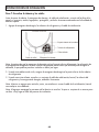
Step 1: Select installation location
Before installing the outdoor unit, choose an appropriate location for the unit. Proper installation locations
meet the following requirements:
• Good air circulation and ventilation.
• Firm and solid; the location can support the unit and will not vibrate.
• Noise from the unit will not be disturbing.
• The unit will be protected from prolonged periods of direct sunlight, rain or snow.
• The location must meet the special requirements outlined below:
Do not install the unit in the following locations:
• Near obstacles that will block air inlets or outlets.
• Near a public street, crowded areas or where noise from the unit will disturb others.
• Near animals or plants that could be harmed by hot air discharge.
• Near any source of combustible gas.
• In a location that is exposed to large amounts of dust.
• In a location that is exposed to large amounts of salty air.
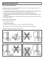
Special Considerations For Extreme Weather
If the unit is exposed to heavy wind, install the unit so that the air outlet fan is at a 90° angle to the
direction of the wind. If needed, build a barrier in front of the unit to protect it from the wind.
If the unit is exposed to heavy rain or snow, build a shelter above the unit to protect it. Be careful not to
obstruct air fl ow around the unit.
If the unit is exposed to salty air, use an outdoor unit that is specially designed to resist corrosion.

15
INSTALLATION INSTRUCTIONS
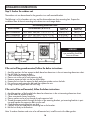
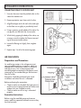
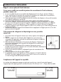
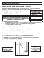
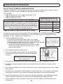
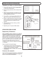
Step 2: Install the drain joint
Before bolting the outdoor unit in place, install the drain joint at the bottom of the unit. There are two types
of drain joint depending on the type of unit.
1. Insert the drain joint into the hole in the base pan of the unit.
2. Rotate the drain joint 90° until it clicks in place facing the front of the unit.
3. Connect a drain hose extension (not included) to the drain joint to redirect water from the unit during
heating mode.
The base hole for the drain joint can be found on the bottom of the unit.
Note For Cold Climates
In cold climates, ensure that the drain hose is positioned as close to vertical as possible to encourage swift
water drainage. If water drains too slowly it can freeze inside the drain hose and fl ood the unit.

16
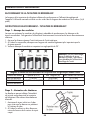
INSTALLATION INSTRUCTIONS
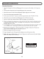
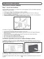
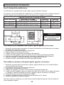
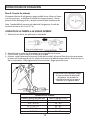
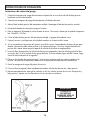
Step 3: Anchor the outdoor unit
The outdoor unit can be anchored to the ground or to a wall-mounted bracket.
The following is a list of outdoor unit sizes and the distance between their mounting feet. Prepare the
installation base of the unit according to the dimensions and images below.
If the unit will be ground mounted, follow the below instructions:
1. Mark the positions for four expansion bolts based on dimensions in the unit mounting dimensions chart.
2. Pre-drill holes for expansion bolts.
3. Clean concrete dust away from holes.
4. Place a nut on the end of each expansion bolt.
5. Hammer expansion bolts into the pre-drilled holes.
6. Remove the nuts from the expansion bolts and place outdoor unit on the bolts.
7. Put washer on each expansion bolt and then replace the nuts.
8. Using a wrench, tighten each nut until snug.
WARNING
When drilling into concrete,
eye protection should be
worn at all times.
If the unit will be wall mounted, follow the below instructions:
1. Mark the positions of the bracket holes based on dimensions in the unit mounting dimensions chart.
2. Pre-drill holes for expansion bolts.
3. Clean concrete dust away from holes.
4. Place a washer and a nut on the end of each expansion bolt.
5. Thread the expansion bolts through the holes on the mounting brackets, put mounting brackets in posi-
tion and hammer the expansion bolts into the wall.
6. Check that the mounting brackets are level.
7. Carefully lift the unit and place its mounting feet on the brackets.
8. Bolt the unit fi rmly to the brackets.
Note: To reduce vibrations and noise of a wall-mounted unit, install the unit with rubber gaskets.
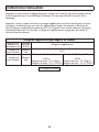
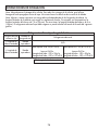
Unit Mounting Dimensions Chart
Model Number Unit Dimensions (W x H x D)
Distance A
(mm / in)
Distance B
(mm / in)
DAS120GBHWDB 730 x 545 x 285 (28.7” x 21.5” x 11.2”) 540 (21.2”) 280 (11”)
DAS170GBHWDB 900 x 700 x 350 (35.4” x 27.6” x 13.8”) 630 (24.8”) 350 (13.8”)
DAS220GBHWDB 900 x 700 x 350 (35.4” x 27.6” x 13.8”) 630 (24.8”) 350 (13.8”)

17
INSTALLATION INSTRUCTIONS
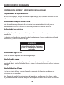
Step 4: Connect the signal and power cables
The outdoor unit’s terminal block is protected by an electrical wiring cover on the side of the unit. A
comprehensive wiring diagram is printed on the inside of the wiring cover.
Cable Types:
• Indoor Power Cable (if applicable): SOW
• Outdoor Power Cable: SOW
• Signal Cable: SOW
1. Prepare the cable for connection:
a. Using wire strippers, strip the rubber jacket from both ends of the signal cable to reveal
about 40 mm (1.57 in) of the wires inside.
b. Strip the insulation from the ends of the wires.
c. Using wire crimper, crimp u-type lugs on the ends of the wires.
2. Unscrew the electrical wiring cover and remove it.
3. Unscrew the cable clamp below the terminal block and place it to the side.
4. Match the wire colours and labels with the labels on the terminal block and fi rmly screw the u-lug of
each wire to its corresponding terminal.
5. After checking to make sure every connection is secure, loop the wires around to prevent rain water
from fl owing into the terminal.
6. Using the cable clamp, fasten the cable to the unit. Screw the cable clamp down tightly.
7. Insulate unused wires with PVC electrical tape. Arrange them so that they do not touch any electrical or
metal parts.
8. Replace the wire cover on the side of the unit and screw it into place.
Minimum Cross Sectional Area of
Power and Signal Cables
Appliance Amps (A) AWG
10 18
13 16
18 14
25 12
30 10
WARNING
All wiring must be performed in accordance with the
wiring diagram located on the inside of the outdoor unit’s
wire cover. Do not mix up live and null wires. This is
dangerous and can cause the appliance to malfunction.
The wiring diagram is
located on the inside of
the wire cover on the
outdoor unit.
Note: Pay attention to the
live wire. While crimping
wires, make sure to
distinguish the Live (“L”)
Wire and other wires.

18
INSTALLATION INSTRUCTIONS
REFRIGERANT PIPING CONNECTION
The length of the refrigerant piping will affect the performance and energy effi ciency of the unit. Nominal
effi ciency is tested on units with a pipe length of 5 m (16.5 ft).
CONNECTION INSTRUCTIONS - REFRIGERANT PIPING
Step 1: Cut pipes
When preparing refrigerant pipes, take extra care to cut and fl are them properly. This will ensure effi cient
operation and minimize the need for future maintenance.
1. Measure the distance between the indoor and outdoor units.
2. Using a pipe cutter, cut the pipe a little longer than the measured distance.
3. Make sure that the pipe is cut at a perfect 90°.
Note: Do not damage, dent or
deform the pipe while cutting.
This will drastically reduce the
heating effi ciency of the unit.
Step 2: Remove burrs
Burrs can affect the air-tight seal of the
refrigerant piping connection. Burrs must be
completely removed.
1. Hold the pipe at a downward angle to
prevent burrs from falling into the pipe.
2. Using a reamer or de-burring tool,
remove all burrs from the cut section of
the pipe.
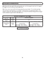
Maximum Length and Drop Height of Refrigerant Piping per Unit Model
Model Number Capacity (BTU/h) Max. Length (m) Max. Drop Height (m)
DAS120GBHWDB < 15,000 25 (82 feet) 10 (33 feet)
DAS170GBHWDB ≥ 15,000 and < 24,000 30 (98.5 feet) 20 (66 feet)
DAS220GBHWDB

19
INSTALLATION INSTRUCTIONS
Step 3: Flare pipe ends
Proper fl aring is essential to achieve an airtight seal.
1. After removing burrs from the cut pipe, seal the ends with PVC tape to prevent foreign materials from
entering the pipe.
2. Sheath the pipe with insulating material.
3. Place fl are nuts on both ends of the pipe. Make sure they are facing in the right direction as they can-
not be removed or adjusted after fl aring.
4. Remove the PVC tape from the ends of the pipe when ready to perform fl aring work.
5. Clamp fl are form on the end of the pipe. The end of the pipe must extend beyond the edge of the fl are
form in accordance with the dimensions shown in the table and image below.
6. Place fl aring tool onto the form.
7. Turn the handle of the fl aring tool clockwise until the pipe is fully fl ared.
8. Remove the fl aring tool and fl are form and then inspect the end of the pipe for cracks and even fl aring.
PIPING EXTENSION BEYOND FLARE FORM
Outer Pipe Diameter (mm) Dimension A Minimum (mm) Dimension A Maximum (mm)
Ø 6.35 (Ø 0.25 in) 0.7 (0.0275 in) 1.3 (0.05 in)
Ø 9.52 (Ø 0.375 in) 1.0 (0.04 in) 1.6 (0.063 in)
Ø 12.7 (Ø 0.5 in) 1.0 (0.04 in) 1.8 (0.07 in)
Ø 16 (Ø 0.63 in) 2.0 (0.078 in) 2.2 (0.086 in)
La page est en cours de chargement...
La page est en cours de chargement...
La page est en cours de chargement...
La page est en cours de chargement...
La page est en cours de chargement...
La page est en cours de chargement...
La page est en cours de chargement...
La page est en cours de chargement...
La page est en cours de chargement...
La page est en cours de chargement...
La page est en cours de chargement...
La page est en cours de chargement...
La page est en cours de chargement...
La page est en cours de chargement...
La page est en cours de chargement...
La page est en cours de chargement...
La page est en cours de chargement...
La page est en cours de chargement...
La page est en cours de chargement...
La page est en cours de chargement...
La page est en cours de chargement...
La page est en cours de chargement...
La page est en cours de chargement...
La page est en cours de chargement...
La page est en cours de chargement...
La page est en cours de chargement...
La page est en cours de chargement...
La page est en cours de chargement...
La page est en cours de chargement...
La page est en cours de chargement...
La page est en cours de chargement...
La page est en cours de chargement...
La page est en cours de chargement...
La page est en cours de chargement...
La page est en cours de chargement...
La page est en cours de chargement...
La page est en cours de chargement...
La page est en cours de chargement...
La page est en cours de chargement...
La page est en cours de chargement...
La page est en cours de chargement...
La page est en cours de chargement...
La page est en cours de chargement...
La page est en cours de chargement...
La page est en cours de chargement...
La page est en cours de chargement...
La page est en cours de chargement...
La page est en cours de chargement...
La page est en cours de chargement...
La page est en cours de chargement...
La page est en cours de chargement...
La page est en cours de chargement...
La page est en cours de chargement...
La page est en cours de chargement...
La page est en cours de chargement...
La page est en cours de chargement...
La page est en cours de chargement...
La page est en cours de chargement...
La page est en cours de chargement...
La page est en cours de chargement...
-
 1
1
-
 2
2
-
 3
3
-
 4
4
-
 5
5
-
 6
6
-
 7
7
-
 8
8
-
 9
9
-
 10
10
-
 11
11
-
 12
12
-
 13
13
-
 14
14
-
 15
15
-
 16
16
-
 17
17
-
 18
18
-
 19
19
-
 20
20
-
 21
21
-
 22
22
-
 23
23
-
 24
24
-
 25
25
-
 26
26
-
 27
27
-
 28
28
-
 29
29
-
 30
30
-
 31
31
-
 32
32
-
 33
33
-
 34
34
-
 35
35
-
 36
36
-
 37
37
-
 38
38
-
 39
39
-
 40
40
-
 41
41
-
 42
42
-
 43
43
-
 44
44
-
 45
45
-
 46
46
-
 47
47
-
 48
48
-
 49
49
-
 50
50
-
 51
51
-
 52
52
-
 53
53
-
 54
54
-
 55
55
-
 56
56
-
 57
57
-
 58
58
-
 59
59
-
 60
60
-
 61
61
-
 62
62
-
 63
63
-
 64
64
-
 65
65
-
 66
66
-
 67
67
-
 68
68
-
 69
69
-
 70
70
-
 71
71
-
 72
72
-
 73
73
-
 74
74
-
 75
75
-
 76
76
-
 77
77
-
 78
78
-
 79
79
-
 80
80


Danby DAS120GBHWDB Le manuel du propriétaire
- Catégorie
- Climatiseurs split-system
- Taper
- Le manuel du propriétaire
- Ce manuel convient également à
dans d''autres langues
Documents connexes
Autres documents
-
NAPOLEON NC19-24F-I-B Manuel utilisateur
-
-
mundoclima Series MUPR-H8A Guide d'installation
-
-
-
MRCOOL MULTI4-36HP230V1 Guide d'installation
-
 Senville SENL12HDO Mode d'emploi
-
-
Panasonic CS-E24RKUAW Guide d'installation
-
Hilti CP 617 Guide d'installation
