Tripp Lite DWTSC3780MUL Manuel utilisateur
- Catégorie
- Supports muraux à panneau plat
- Taper
- Manuel utilisateur

1
Owner’s Manual
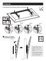
Tilt Wall Mount
for Flat and Curved Screens –
Security Version
Model: DWTSC3780MUL
Español 9 • Français 17 • Русский 25 • Deutsch 33
PROTECT YOUR INVESTMENT!
Register your product for quicker service and ultimate peace of mind.
You could also win an ISOBAR6ULTRA surge protector—a $100 value!
www.tripplite.com/warranty
1111 W. 35th Street, Chicago, IL 60609 USA • www.tripplite.com/support
Copyright © 2018 Tripp Lite. All rights reserved.
300x300 / 400x200 /
400x400 / 600x400
80”
MAX
88 lb.
(40 kg)
MAX

2
Important Safety Instructions
Warranty & Product Registration
NOTE: Read the entire instruction manual before you start installation and assembly.
WARNING
• Do not begin the installation until you have read and understood the instructions and warnings contained in this manual. If you have
any questions regarding any of the instructions or warnings, please visit www.tripplite.com/support.
• This mounting bracket was designed to be installed and utilized ONLY as specified in this manual. Improper installation of this
product may cause damage or serious injury.
• This product should only be installed by someone of good mechanical ability, with basic building experience and a full understanding
of this instruction manual.
• Make sure that the mounting surface can safely support the combined load of the equipment and all attached hardware and
components.
• If mounting to wood wall studs, make sure that mounting screws are anchored into the center of the studs. The use of a stud finder
is highly recommended.
• Always use an assistant or mechanical lifting equipment to safely lift and position equipment.
• Tighten screws firmly, but do not over-tighten. Over-tightening can damage the items, greatly reducing their holding power.
• This product is intended for indoor use only. Using this product outdoors could lead to product failure and personal injury.
5-Year Limited Warranty
Seller warrants this product, if used in accordance with all applicable instructions, to be free from original defects in material and workmanship for a period of 5 years from the date
of initial purchase. If the product should prove defective in material or workmanship within that period, Seller will repair or replace the product, in its sole discretion.
THIS WARRANTY DOES NOT APPLY TO NORMAL WEAR OR TO DAMAGE RESULTING FROM ACCIDENT, MISUSE, ABUSE OR NEGLECT. SELLER MAKES NO EXPRESS WARRANTIES
OTHER THAN THE WARRANTY EXPRESSLY SET FORTH HEREIN. EXCEPT TO THE EXTENT PROHIBITED BY APPLICABLE LAW, ALL IMPLIED WARRANTIES, INCLUDING ALL WARRANTIES
OF MERCHANTABILITY OR FITNESS, ARE LIMITED IN DURATION TO THE WARRANTY PERIOD SET FORTH ABOVE; AND THIS WARRANTY EXPRESSLY EXCLUDES ALL INCIDENTAL AND
CONSEQUENTIAL DAMAGES. (Some states do not allow limitations on how long an implied warranty lasts, and some states do not allow the exclusion or limitation of incidental or
consequential damages, so the above limitations or exclusions may not apply to you. This warranty gives you specific legal rights, and you may have other rights which vary from
jurisdiction to jurisdiction).
WARNING: The individual user should take care to determine prior to use whether this device is suitable, adequate or safe for the use intended. Since individual applications are
subject to great variation, the manufacturer makes no representation or warranty as to the suitability or fitness of these devices for any specific application.
PRODUCT REGISTRATION
Visit www.tripplite.com/warranty today to register your new Tripp Lite product. You’ll be automatically entered into a drawing for a chance to win a FREE Tripp Lite product!*
* No purchase necessary. Void where prohibited. Some restrictions apply. See website for details.
Tripp Lite has a policy of continuous improvement. Specifications are subject to change without notice.

3
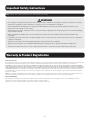
IMPORTANT: Ensure all parts according to the component checklist have been received prior to installation. If any parts are
missing or faulty, visit www.tripplite.com/support for service.
Component Checklist
Wall Plate (x1)
M5 x 14 (x4) M6 x 14 (x4) M6 x 30 (x4)M8 x 20 (x4) M8 x 30 (x4) Washer (x4) Small
Spacer (x8)
Big
Spacer (x4)
Anchor Bolt (x6) Concrete Anchor
(x6)
20 mm Washer
(x6)
Security Bar (x1) Left Adapter Bracket (x1) Right Adapter Bracket (x1)
End Cap (x2)Wall Plate Level
(x1)
Combo Lock (x1)End Cap
Screws (x4)
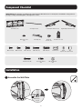
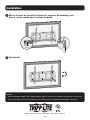
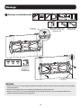
Installation
1
Assemble the Wall Plate
End Cap
Screws
End Cap

4
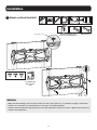
Installation
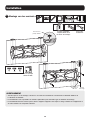
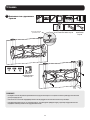
2A
Mount on Wood Stud Wall
WARNING
• Make sure that mounting screws are anchored into the center of the studs. Use of a stud finder is highly recommended.
• Installers are responsible to provide hardware for other types of mounting situations.
• Installers must verify that the supporting surface will safely support the combined load of the equipment and all attached
hardware and components.
20 mm
Washer
Wall Plate Level
Anchor
Bolt
55 mm
(2.2 in.)
O4.5 mm
O(3/16 in.)
Find and mark the exact
location of mounting holes
Screw the
assembled wall
plate onto the
wall
Drill pilot holes

5
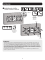
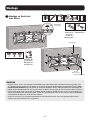
Installation
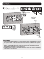
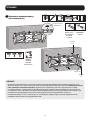
2B
Mount on Solid Brick
and Concrete Block
WARNING
• When installing wall mounts onto a concrete masonry unit (also known as a CMU or “cinder block”), verify that the actual
concrete thickness is at least 35 mm (1-3/8”) in order to hold the concrete anchors. DO NOT DRILL INTO MORTAR JOINTS!
Be sure to mount the assembled wall-mount plate with the included concrete anchors, D6 washers and anchor bolts
onto solid sections of the blocks. The solid sections can generally be found 25mm (1”) toward the middle of the block
from either end. An electric drill on a slow setting is suggested to drill the hole rather than a hammer drill so as to avoid
breaking out the back of the hole when entering a hollow section.
• Installers must verify that the supporting surface will safely support the combined load of the equipment and all attached
hardware and components.
Wall Plate Level
60 mm
(2.4 in.)
O10 mm
O(3/8 in.)
Find and mark
the exact
location of
mounting holes
Drill pilot holes
Screw the
assembled wall
plate onto the
wall
20 mm
Washer
Anchor
Bolt
Concrete
Anchor

6
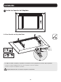
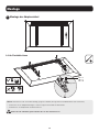
Installation
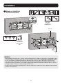
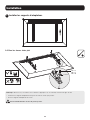
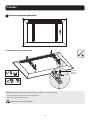
3
Install Adapter Brackets
3-1 For Flat Back Screen
M5 x 14
M6 x 14
M8 x 20
Washer
Note: Choose appropriate screws, washers and spacers (if necessary) according to the type of screen.
• Position the adapter brackets as close as possible to the center of the display.
• Screw the adapter brackets onto the display.
Firmly secure all screws. Do not over-tighten.

7
Installation
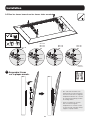
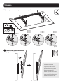
3-2 For Curved Screen or Recessed Back Screen
M8 x 20
M8 x 20
M6 x 30
M8 x 30
M6 x 30
M8 x 30
M6 x 30
M8 x 30
Washer
Washer
Washer
Washer
Small
Spacer
Small
Spacer
Big
Spacer
Small
Spacer
Big
Spacer
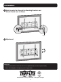
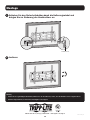
4
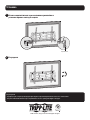
Hang Display
onto the
Wall Plate
• Using an assistant or mechanical
lifting equipment, hook the display
with attached adapter brackets over
the top of the mounted wall plate.
• Push the safety clamps on the
bottom of the adapter brackets
upward and tighten the two screws
to lock each bracket to the wall
plate.
Wall
Wall

8
1111 W. 35th Street, Chicago, IL 60609 USA • www.tripplite.com/support
Maintenance
• Check that the bracket is secure and safe to use at regular intervals (at least every three months).
• Please visit www.tripplite.com/support if you have any questions.
Installation
5
Slide Security Bar through the Mounting Brackets and
Attach Combo Lock to Secure
6
Adjustment
Combo
Lock
Security Bar

9
Manual del Propietario
Soporte Inclinable para Pared
para Pantallas Planas y
Curvas – Versión de Seguridad
Modelo: DWTSC3780MUL
English 1 • Français 17 • Русский 25 • Deutsch 33
1111 W. 35th Street, Chicago, IL 60609 EE. UU. • www.tripplite.com/support
Copyright © 2018 Tripp Lite. Todos los derechos reservados.
300x300 / 400x200 /
400x400 / 600x400
80”
MÁX
[88 lb]
40 kg
MÁX

10
Instrucciones de Seguridad Importantes
Garantía
NOTA: Lea todo el manual de instrucciones antes de iniciar la instalación y ensamble.
ADVERTENCIA
• No inicie la instalación hasta que haya leído y entendido las instrucciones y advertencias contenidas en este manual. Si tiene
cualquier pregunta con respecto a cualquiera de las instrucciones o advertencias, visite www.tripplite.com/support.
• Este soporte para instalación fue diseñado para ser instalado y utilizado SOLAMENTE como se especifica en este manual. La
instalación incorrecta de este producto puede causar daños o lesiones severas.
• Este producto debe ser instalado únicamente por alguien con una buena habilidad mecánica, experiencia básica de construcción y
un entendimiento completo de este manual de instrucciones.
• Cerciórese que la superficie de instalación pueda soportar con seguridad la carga combinada de todo el hardware y componentes
instalados.
• Si se instala en paredes con entramados de madera, cerciórese que los tornillos de instalación estén anclados en el centro de los
entrepaños. Es muy recomendable usar un detector de vigas.
• Utilice siempre un ayudante o equipo de elevación mecánico para levantar y colocar el equipo con seguridad.
• Apriete los tornillos firmemente pero no en exceso. Apretar excesivamente puede dañar los componentes, reduciendo severamente
su capacidad de soporte.
• Este producto está diseñado para usarse sólo en interiores. Usar este producto en exteriores podría derivar en fallas del producto y
lesiones personales.
Garantía Limitada por 5 Años
El vendedor garantiza este producto, si se usa de acuerdo con todas las instrucciones aplicables, de que está libre de defectos en material y mano de obra por un período de 5
años a partir de la fecha de compra inicial. Si el producto prueba ser defectuoso en material o mano de obra dentro de ese período, el vendedor reparará o reemplazará el producto
a su entera discreción.
ESTA GARANTÍA NO SE APLICA AL DESGASTE NORMAL O A LOS DAÑOS QUE RESULTEN DE ACCIDENTES, USO INCORRECTO, USO INDEBIDO O NEGLIGENCIA. EL VENDEDOR NO
OTORGA GARANTÍAS EXPRESAS DISTINTAS DE LA ESTIPULADA EN EL PRESENTE. SALVO EN LA MEDIDA EN QUE LO PROHÍBAN LAS LEYES APLICABLES, TODAS LAS GARANTÍAS
IMPLÍCITAS, INCLUYENDO TODAS LAS GARANTÍAS DE COMERCIALIZACIÓN O IDONEIDAD, ESTÁN LIMITADAS EN DURACIÓN AL PERÍODO DE GARANTÍA ESTABLECIDO; ASIMISMO,
ESTA GARANTÍA EXCLUYE EXPRESAMENTE TODOS LOS DAÑOS INCIDENTALES E INDIRECTOS. (Algunos estados no permiten limitaciones en cuanto a la duración de una garantía
y algunos estados no permiten la exclusión o limitación de daños incidentales o indirectos, de modo que las limitaciones anteriores pueden no aplicar para usted. Esta garantía le
otorga derechos legales específicos y usted puede tener otros derechos que pueden variar de una jurisdicción a otra).
ADVERTENCIA: antes de usarlo, cada usuario debe tener cuidado al determinar si este dispositivo es adecuado o seguro para el uso previsto. Ya que las aplicaciones individuales
están sujetas a gran variación, el fabricante no garantiza la adecuación de estos dispositivos para alguna aplicación específica.

11
IMPORTANTE: Asegúrese antes de instalar, de haber recibido todas las partes de acuerdo a la lista de comprobación de
componentes. Si faltase cualquier parte o estuviese dañada, visite www.tripplite.com/support para solicitar servicio.
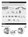
Accesorios y Partes Incluidas en el Empaque
Placa de Pared
(x1)
M5 x 14
(x4)
M6 x 14
(x4)
M6 x 30
(x4)
M8 x 20
(x4)
M8 x 30
(x4)
Arandela
(x4)
Espaciador
Pequeño
(x8)
Espaciador
Grande
(x4)
Tornillo de Anclaje
(x6)
Taquete
(x6)
Arandela de 20 mm
(x6)
Barra de Seguridad
(x1)
Soporte Adaptador Izquierdo
(x1)
Soporte Adaptador Derecho
(x1)
Tapa de Extremo
(x2)
Nivel de Placa de Pared
(x1)
Candado de
Combinación
(x1)
Tornillos de Tapa
de Extremo
(x4)
Instalación
1
Ensamble la Placa de Pared
Tornillos de
Tapa de
Extremo
Tapa de
Extremo

12
Instalación
2A
Instalación en Pared sobre
Entramado de Madera
ADVERTENCIA
• Cerciórese que los tornillos de instalación estén anclados en el centro de los entrepaños. Es muy recomendable usar un
detector de vigas.
• Los instaladores son responsables de proporcionar los accesorios para otros tipos de instalación.
• Los instaladores deben verificar que la superficie de apoyo soporte con seguridad la carga combinada de todo el
hardware y componentes instalados.
Arandela de
20 mm
Nivel de Placa
de Pared
Tornillo
de Anclaje
55 mm
[2.2"]
Ø 4.5 mm
Ø [3/16"]
Encuentre y marque la posición
exacta de los orificios de
instalación
Atornille la
placa de pared
ensamblada a la
pared
Barrene los
orificios piloto

13
Instalación
2B
Instalación sobre Ladrillos
Sólidos y Bloques de Concreto
ADVERTENCIA
• Al instalar soportes de pared en una unidad de mampostería de concreto (conocida también como de bloques de
concreto), verifique que el espesor real del concreto sea de al menos 35 mm [1 3/8”] a fin de sujetar los taquetes
para concreto. ¡NO TALADRE EN LAS UNIONES DE ARGAMASA! Asegúrese de instalar la placa de pared ensamblada
con los taquetes para concreto, arandelas D6 y tornillos de anclaje incluidos en las secciones sólidas de los bloques.
Las secciones sólidas pueden encontrarse generalmente a 25 mm (1”) hacia el centro del bloque en cada extremo. Se
sugiere utilizar un taladro eléctrico a baja velocidad para barrenar el orificio en vez de un rotomartillo para evitar rotura
de la parte posterior del orificio al entrar en una sección hueca.
• Los instaladores deben verificar que la superficie de apoyo soporte con seguridad la carga combinada de todo el
hardware y componentes instalados.
Nivel de Placa de
Pared
60 mm
[2.4"]
Ø 10 mm
Ø [3/8"]
Encuentre
y marque
la posición
exacta de los
orificios de
instalación
Barrene los
orificios piloto
Atornille la
placa de pared
ensamblada a
la pared
Arandela de
20 mm
Tornillo
de Anclaje
Taquete

14
Instalación
3
Instale los Soportes del Adaptador
3-1 Para Pantalla con Respaldo Plano
M5 x 14
M6 x 14
M8 x 20
Arandela
Nota: Elija los tornillos, arandelas y espaciadores (si fueran necesarios) apropiados de acuerdo al tipo de pantalla.
• Coloque los soportes adaptadores tan cerca como sea posible al centro de la pantalla.
• Atornille los soportes del adaptador a la pantalla.
Asegure firmemente todos los tornillos. No apriete excesivamente

15
Instalación
3-2 Para Pantalla Curva o Pantalla de Parte Posterior Cóncava
M8 x 20
M8 x 20
M6 x 30
M8 x 30
M6 x 30
M8 x 30
M6 x 30
M8 x 30
Arandela
Arandela
Arandela
Arandela
Espaciador
Pequeño
Espaciador
Pequeño
Espaciador
Grande
Espaciador
Pequeño
Espaciador
Grande
4
Cuelgue la Pantalla
en la Placa de Pared
• Usando un ayudante o equipo
de elevación mecánico, cuelgue
la pantalla con los soportes del
adaptador colocados sobre la
parte superior de la placa de pared
instalada.
• Empuje hacia arriba las abrazaderas
de seguridad en la parte inferior de
los soportes adaptadores y apriete
los dos tornillos para asegurar cada
soporte a la placa de pared.
Pared
Pared

16
1111 W. 35th Street, Chicago, IL 60609 EE. UU. • www.tripplite.com/support
Mantenimiento
• Compruebe a intervalos regulares (al menos cada tres meses) que el soporte esté seguro para usarse.
• Si tiene alguna pregunta, visite por favor a www.tripplite.com/support.
Instalación
5
Deslice la barra de seguridad a través de los soportes de instalación e
instale el candado de combinación para asegurarla
6
Ajuste
Candado de
Combinación
Barra de
Seguridad

17
Manuel de l'utilisateur
Montage mural inclinable
pour écrans plats ou
incurvés – version sécurité
Modèle : DWTSC3780MUL
English 1 • Español 9 • Русский 25 • Deutsch 33
1111 W. 35th Street, Chicago, IL 60609 USA • www.tripplite.com/support
Droits d'auteur © 2018 Tripp Lite. Tous droits réservés.
300x300 / 400x200 /
400x400 / 600x400
203,2 cm
(80 po)
MAX
40 kg
(88 lb)
MAX

18
Consignes de sécurité importantes
Garantie
REMARQUE : Lire le manuel d'instructions en entier avant de commencer l'installation et l'assemblage.
AVERTISSEMENT
• Ne pas commencer l'installation avant d'avoir lu et compris les instructions et les avertissements contenus dans le présent manuel.
Pour toute question concernant les instructions ou les avertissements, visiter www.tripplite.com/support.
• Ce support de montage a été conçu pour être installé et utilisé UNIQUEMENT comme spécifié dans le présent manuel. Une
mauvaise installation risque de causer des dommages ou des blessures graves.
• Ce produit ne devrait être installé que par une personne ayant de bonnes aptitudes en mécanique et une expérience de base en
construction de même qu'une pleine connaissance du présent manuel d'instructions.
• S'assurer que la surface de montage peut supporter sans risque la charge combinée de l'équipement et de tout le matériel et
composants attachés.
• Si le produit est monté sur des montants muraux en bois, s'assurer que les vis de montage sont ancrées au centre des montants. Il
est fortement recommandé d'utiliser un localisateur de montants.
• Toujours faire appel à un assistant ou utiliser de l'équipement de levage mécanique pour soulever et mettre en place l'équipement.
• Serrer fermement les vis, mais sans trop serrer. Trop serrer les vis risquerait d'endommager les articles, réduisant considérablement
leur résistance à l'arrachement.
• Ce produit est prévu pour être utilisé à l'intérieur uniquement. L'utilisation de ce produit à l'extérieur pourrait entraîner une
défaillance du produit et des lésions corporelles.
Garantie limitée de 5 ans
Le vendeur garantit ce produit, s'il est utilisé conformément à toutes les instructions applicables, est exempt de tous défauts de matériaux et de fabrication pour une période de 5
ans à partir de la date d'achat initiale. Si le produit s'avère défectueux en raison d'un vice de matière ou de fabrication au cours de cette période, le vendeur s'engage à réparer ou
remplacer le produit, à sa seule discrétion.
CETTE GARANTIE NE S'APPLIQUE PAS À L'USURE NORMALE OU AUX DOMMAGES RÉSULTANT D'UNE MAUVAISE UTILISATION, D'UN ABUS OU D'UNE NÉGLIGENCE. LE VENDEUR
NE DONNE AUCUNE GARANTIE EXPRESSE AUTRE QUE LA GARANTIE EXPRESSÉMENT DÉCRITE DANS LE PRÉSENT DOCUMENT. SAUF DANS LA MESURE INTERDITE PAR LA LOI
APPLICABLE, TOUTE GARANTIE IMPLICITE, Y COMPRIS TOUTES LES GARANTIES DE QUALITÉ MARCHANDE OU D'ADAPTATION, SONT LIMITÉES À LA PÉRIODE DE GARANTIE CI-
DESSUS ET CETTE GARANTIE EXCLUT EXPRESSÉMENT TOUS DOMMAGES DIRECTS ET INDIRECTS. (Certains États ne permettent pas de limitations sur la durée d'une garantie
implicite, et certains États ne permettent pas l'exclusion ou la limitation des dommages fortuits ou consécutifs, de sorte que les limitations ou exclusions susmentionnées peuvent
ne pas s'appliquer à vous. Cette garantie vous donne des droits légaux spécifiques, et vous pouvez avoir d'autres droits qui varient selon la juridiction).
AVERTISSEMENT : L'utilisateur individuel doit prendre soin de déterminer avant l'utilisation si cet appareil est approprié, adéquat et sûr pour l'usage prévu. Puisque les utilisations
individuelles sont sujettes à des variations importantes, le fabricant ne fait aucune déclaration ou garantie quant à l'aptitude ou l'adaptation de ces dispositifs pour une application
spécifique.

19
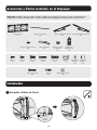
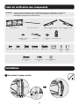
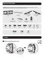
IMPORTANT : S'assurer d'avoir reçu toutes les pièces conformément à la liste de vérification des composants
avant de procéder à l'installation. Si des pièces sont manquantes ou défectueuses, visitez
www.tripplite.com/support pour obtenir de l'aide.
Liste de vérification des composants
Plaque murale (x1)
M5 x 14 (x4) M6 x 14 (x4) M6 x 30 (x4)M8 x 20 (x4) M8 x 30 (x4) Rondelle (x4) Petite
entretoise
(x8)
Grande
entretoise
(x4)
Boulon d'ancrage
(x6)
Ancrage à béton
(x6)
Rondelle de 20 mm
(x6)
Barre de sécurité (x1) Support d'adaptateur gauche
(x1)
Support d'adaptateur droit
(x1)
Embout (x2)Niveau de la plaque
murale (x1)
Verrou combo (x1)Vis d'embout
(x4)
Installation
1
Assembler la plaque murale
Vis d'em-
bout
Embout

20
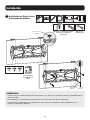
Installation
2A
Montage sur des montants muraux
AVERTISSEMENT
• S'assurer que les vis de montage sont ancrées au centre des montants. Il est fortement recommandé d'utiliser un
localisateur de montants.
• Les installateurs sont responsables de fournir la quincaillerie pour tout autre type de situations de montage.
• Les installateurs doivent s'assurer que la surface d'appui va supporter sans risque la charge combinée de l'équipement et
de tout le matériel et composants attachés.
Rondelle de
20 mm
Niveau de la
plaque murale
Boulon
d'ancrage
55 mm
(2,2 po)
O 4,5 mm
O (3/16 po)
Trouver et marquer
l’emplacement exact
des trous de montage.
Visser la plaque
murale au mur.
Percer des
avant-trous.
La page est en cours de chargement...
La page est en cours de chargement...
La page est en cours de chargement...
La page est en cours de chargement...
La page est en cours de chargement...
La page est en cours de chargement...
La page est en cours de chargement...
La page est en cours de chargement...
La page est en cours de chargement...
La page est en cours de chargement...
La page est en cours de chargement...
La page est en cours de chargement...
La page est en cours de chargement...
La page est en cours de chargement...
La page est en cours de chargement...
La page est en cours de chargement...
La page est en cours de chargement...
La page est en cours de chargement...
La page est en cours de chargement...
La page est en cours de chargement...
-
 1
1
-
 2
2
-
 3
3
-
 4
4
-
 5
5
-
 6
6
-
 7
7
-
 8
8
-
 9
9
-
 10
10
-
 11
11
-
 12
12
-
 13
13
-
 14
14
-
 15
15
-
 16
16
-
 17
17
-
 18
18
-
 19
19
-
 20
20
-
 21
21
-
 22
22
-
 23
23
-
 24
24
-
 25
25
-
 26
26
-
 27
27
-
 28
28
-
 29
29
-
 30
30
-
 31
31
-
 32
32
-
 33
33
-
 34
34
-
 35
35
-
 36
36
-
 37
37
-
 38
38
-
 39
39
-
 40
40


Tripp Lite DWTSC3780MUL Manuel utilisateur
- Catégorie
- Supports muraux à panneau plat
- Taper
- Manuel utilisateur
dans d''autres langues
Documents connexes
-
Tripp Lite DWFSC3780MUL Le manuel du propriétaire
-
Tripp Lite DWF3270X Le manuel du propriétaire
-
-
-
-
-
Tripp Lite DWTSC3255MUL Le manuel du propriétaire
-
Tripp Lite DWT3780XUL Le manuel du propriétaire
-
-