Tripp Lite DMVWSC4570XUL Le manuel du propriétaire
- Catégorie
- Supports muraux à panneau plat
- Taper
- Le manuel du propriétaire

1
1111 W. 35th Street, Chicago, IL 60609 USA • www.tripplite.com/support
Copyright © 2019 Tripp Lite. All rights reserved.
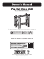
Owner’s Manual
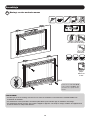
Pop-Out Video Wall
Model: DMVWSC4570XUL
200x200 / 300x200 / 300x300
400x200 / 400x300 / 400x400
600x400
70"
MAX
154 lb.
(70 kg)
RATED
For additional instructions on installing more than one video mount, visit www.tripplite.com.
WARRANTY REGISTRATION
Register your product today and be
automatically entered to win an ISOBAR
surge protector in our monthly drawing!
www.tripplite.com/warranty
Español 16 • Français 31 • Русский 46 • Deutsch 61

2
NOTE: Read the entire instruction manual before you start assembly and installation.
Warranty and Product Registration
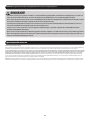
WARNING
• Do not begin the installation until you have read and understood the instructions and warnings contained in this manual.
If you have any questions regarding any of the instructions or warnings, please visit www.tripplite.com/support
• This product was designed to be installed and utilized ONLY as specified in this manual. Improper installation of this product
may cause damage or serious injury.
• This product should only be installed by someone of good mechanical ability, with basic building experience and a full
understanding of this instruction manual.
• Make sure that the unit can safely support the combined load of the equipment and all attached hardware and components.
• Always use an assistant or mechanical lifting equipment to safely lift and position equipment.
• This product is intended for indoor use only. Using this product outdoors could lead to product failure and personal injury.
5-Year Limited Warranty
Seller warrants this product, if used in accordance with all applicable instructions, to be free from original defects in material and workmanship for a period of 5 years from the date
of initial purchase. If the product should prove defective in material or workmanship within that period, Seller will repair or replace the product, in its sole discretion.
THIS WARRANTY DOES NOT APPLY TO NORMAL WEAR OR TO DAMAGE RESULTING FROM ACCIDENT, MISUSE, ABUSE OR NEGLECT. SELLER MAKES NO EXPRESS WARRANTIES
OTHER THAN THE WARRANTY EXPRESSLY SET FORTH HEREIN. EXCEPT TO THE EXTENT PROHIBITED BY APPLICABLE LAW, ALL IMPLIED WARRANTIES, INCLUDING ALL WARRANTIES
OF MERCHANTABILITY OR FITNESS, ARE LIMITED IN DURATION TO THE WARRANTY PERIOD SET FORTH ABOVE; AND THIS WARRANTY EXPRESSLY EXCLUDES ALL INCIDENTAL AND
CONSEQUENTIAL DAMAGES. (Some states do not allow limitations on how long an implied warranty lasts, and some states do not allow the exclusion or limitation of incidental or
consequential damages, so the above limitations or exclusions may not apply to you. This warranty gives you specific legal rights, and you may have other rights which vary from
jurisdiction to jurisdiction).
WARNING: The individual user should take care to determine prior to use whether this device is suitable, adequate or safe for the use intended. Since individual applications are
subject to great variation, the manufacturer makes no representation or warranty as to the suitability or fitness of these devices for any specific application.
PRODUCT REGISTRATION
Visit www.tripplite.com/warranty today to register your new Tripp Lite product. You’ll be automatically entered into a drawing for a chance to win a FREE Tripp Lite product!*
* No purchase necessary. Void where prohibited. Some restrictions apply. See website for details.
Tripp Lite has a policy of continuous improvement. Specifications are subject to change without notice. Photos and illustrations may differ slightly from actual products.

3
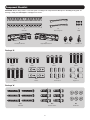
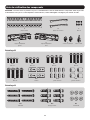
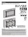
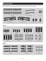
Component Checklist
IMPORTANT: Ensure that you have received all parts according to the component checklist prior to installing. If any parts are
missing or faulty, visit www.tripplite.com/support for service.
A
Wall Plate
C
M5x8
D
Left Adapter Bracket
F
Plastic Locks
G
Combo Lock
E
Right Adapter Bracket
B
Connecting Plate
Package M
Package W
M-A
M5x14
M-E
M8x30
W-A
ST6.3x55
M-B
M6x14
M-F
Washer
M-C
M8x20
M-G
Small Spacer
W-B
Concrete Anchor
M-D
M6x30
M-H
Big Spacer
W-C
D6 Washer

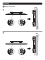
4
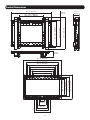
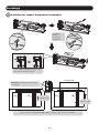
Product Dimensions
26.4 in. (670 mm)
26.4 in. (670 mm)
22.6 in. (575 mm)
20.7 in. (525 mm)
18.7 in. (475 mm)
16.7 in. (425 mm)
14.8 in. (375 mm)
12.8 in. (325 mm)
3 in.
(75 mm)
4.9 in.
(125 mm)
6.9 in. (175 mm)
8.9 in. (225 mm)
10.8 in. (275 mm)
3.74 in.
(95 mm)
Min: 7.9 in. (200 mm)
Max: 16.5 in. (418 mm)
10.9 in. (276 mm)
12 in. (304 mm)
13.5 in. (344 mm)
16.4 in. (416 mm)
16.4 in. (416 mm)
20 in. (524 mm)
2.12 in.
(54 mm)
3.74 in.
(95 mm)
Min: 7.9 in. (200 mm)
Max: 23.6 in. (600 mm)

5
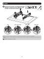
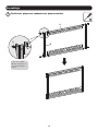
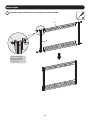
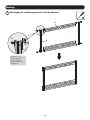
Assembly
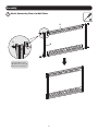
1
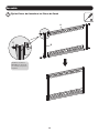
Attach Connecting Plates to Wall Plates
E
A
B
Using the M5x8 screws
(E), attach the connecting
plates to the wall plates.

6
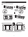
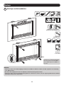
W-A
W-C
55 mm
(2.2 in.)
O/ 4.5 mm
O/ (3/16 in.)
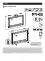
Mark the exact location of
mounting holes
Drill pilot
holes
Screw the
wall plate
onto the
wall
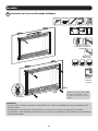
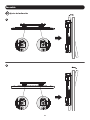
Using the ST6.3x55 screws (W-A)
and D6 washers (W-C), attach wall
plate assembly to the wall.
WARNING
• Make sure that mounting screws are anchored into the center of the studs. Use of a stud finder is highly recommended.
• Installers are responsible to provide hardware for other types of mounting situations.
• Installers must verify that the supporting surface will safely support the combined load of the equipment and all attached
hardware and components.
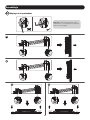
Assembly
2a
Mount on Wood Stud Wall

7
Assembly
2b
Mount on Solid Brick or Concrete Block Wall
W-B
W-A
W-C
60 mm
(2.4 in.)
O/ 10 mm
O/ (3/8 in.)
Mark the exact
location of
mounting holes
Drill pilot
holes
Screw the
wall plate
onto the
wall
Using the ST6.3x55 screws (W-A), D6
washers (W-C) and concrete anchors (W-B),
attach wall plate assembly to the wall.
WARNING
• When installing wall mounts onto a concrete masonry unit (also known as a CMU or “cinder block”), verify that the actual
concrete thickness is at least 35 mm (1-3/8”) in order to hold the concrete anchors. DO NOT DRILL INTO MORTAR JOINTS!
Be sure to mount the assembled wall-mount plate with the included concrete anchors, washers and anchor bolts onto solid
sections of the blocks.
The solid sections can generally be found 25 mm (1”) toward the middle of the block from either end. An electric drill on a
slow setting is suggested to drill the hole rather than a hammer drill so as to avoid breaking out the back of the hole when
entering a hollow section.
• Installers must verify that the supporting surface will safely support the combined load of the equipment and all attached
hardware and components.

8
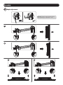
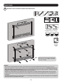
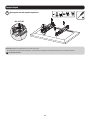
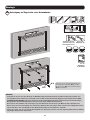
Assembly
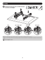
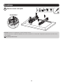
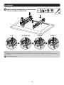
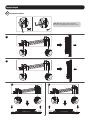
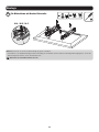
3
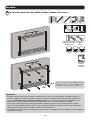
Install the Pop-Out Adapter Brackets
Hex Key
Ball Joint
Remove the hex
key from the
adapter brackets.
Push the pop-out arm until the ball joint snaps
into place.
D DCC
VESA 600x400
Note: Make sure the arrow is pointing up.
For VESA 600x400 mounting patterns, the “D” and “C” positions are flipped.
Top of the
display.
Top of the
display.

9
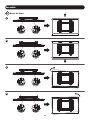
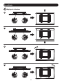
Assembly
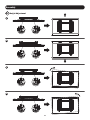
3a
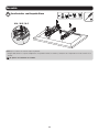
For Flat Back Screens
M-F
M-A / M-B / M-C
Note: Choose appropriate screws according to the type of screen.
• Firmly secure the adapter brackets onto the display using the screws and any other necessary hardware components included with the
unit.
Do not over-tighten screws.

10
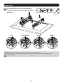
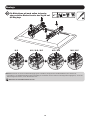
Assembly
3b
For Bump-Out Screen, Recessed Back Screen
or to Access A/V Inputs
M-C M-C / M-D / M-E M-D / M-E M-D / M-E
M-G
M-G
M-G
M-H
M-H
M-F M-F
M-F
M-F
or or or
Note: Choose appropriate screws, washers and spacers (if necessary) according to the type of screen.
• Firmly secure the adapter brackets onto the display using the screws and any other necessary hardware components included with the
unit.
Do not over-tighten screws.

11
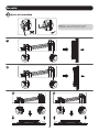
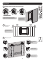
Assembly
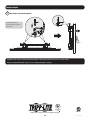
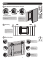
4
5
Attach the Display onto the Wall Plate
Adjustment
G
Locking Plate
Turn the locking plates downward to fasten the
wall plate. Tighten the screws to secure.
Use a padlock to
prevent the display
from tampering or
theft.
For fast alignment, push
the display to the left or
right.
5a
Micro Adjustment
For tilt adjustment.
For in/out micro
adjustment.
For up/down micro
adjustment.

12
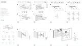
Assembly
5b
Tilt Adjustment
1
2

13
Assembly
5c
Height Adjustment
1
2
3
4

14
Assembly
5d
Depth Adjustment
1
2
3 4
Note: Only use the long end of the hex key
when tightening the adjustment screws.

15
Assembly
6
Secure and Lock the Display
Use the plastic locks (F) to
lock the display in place.
F
• Check that the bracket is secure and safe to use at regular intervals (at least every three months).
• Please visit www.tripplite.com/support if you have any questions.
1111 W. 35th Street, Chicago, IL 60609 USA • www.tripplite.com/support
19-02-230 93-3945_RevA
LVW06-46T

16
1111 W. 35th Street, Chicago, IL 60609 EE UU • En la dirección de correo electrónico www.tripplite.com/support
Copyright © 2019 Tripp Lite. Todos los derechos reservados.
Manual del Propietario
Muro de Video Emergente
Modelo: DMVWSC4570XUL
200x200 / 300x200 / 300x300 /
400x200 / 400x300 / 400x400
/ 600x400
70"
MÁXIMO
70 kg
[154 lb]
CLASIFICADO
Para más instrucciones sobre la instalación de más de un soporte para video, visite www.tripplite.com.
English 1 • Françaís 31 • Русский 46 • Deutsch 61

17
NOTA: Lea todo el manual de instrucciones antes de iniciar la instalación y ensamble.
Garantía
ADVERTENCIA
• No inicie la instalación hasta que haya leído y entendido las instrucciones y advertencias contenidas en este manual.
Si tiene cualquier pregunta con respecto a cualquiera de las instrucciones o advertencias, visite www.tripplite.com/support.
• Este producto fue diseñado para ser instalado y utilizado SOLAMENTE como se especifica en este manual. La instalación
incorrecta de este producto puede causar daños o lesiones severas.
• Este producto debe ser instalado únicamente por alguien con una buena habilidad mecánica, experiencia básica de
construcción y un entendimiento completo de este manual de instrucciones.
• Cerciórese que la unidad pueda soportar con seguridad la carga combinada de todo el hardware y componentes instalados.
• Utilice siempre un ayudante o equipo de elevación mecánico para levantar y colocar el equipo con seguridad.
• Este producto está diseñado para usarse sólo en interiores. Usar este producto en exteriores podría derivar en fallas del
producto y lesiones personales.
Garantía Limitada por 5 Años
El vendedor garantiza este producto, si se usa de acuerdo con todas las instrucciones aplicables, de que está libre de defectos en material y mano de obra por un período de 5
años a partir de la fecha de compra inicial. Si el producto resultara defectuoso en material o mano de obra dentro de ese período, el vendedor reparará o reemplazará el producto a
su entera discreción.
ESTA GARANTÍA NO SE APLICA AL DESGASTE NORMAL O A LOS DAÑOS QUE RESULTEN DE ACCIDENTES, USO INCORRECTO, USO INDEBIDO O NEGLIGENCIA. EL VENDEDOR NO
OTORGA GARANTÍAS EXPRESAS DISTINTAS A LA ESTIPULADA EN EL PRESENTE. SALVO EN LA MEDIDA EN QUE LO PROHÍBAN LAS LEYES APLICABLES, TODAS LAS GARANTÍAS
IMPLÍCITAS, INCLUYENDO TODAS LAS GARANTÍAS DE COMERCIALIZACIÓN O IDONEIDAD, ESTÁN LIMITADAS EN DURACIÓN AL PERÍODO DE GARANTÍA ESTABLECIDO; ASIMISMO,
ESTA GARANTÍA EXCLUYE EXPRESAMENTE TODOS LOS DAÑOS INCIDENTALES E INDIRECTOS. (Algunos estados no permiten limitaciones en cuanto a la duración de una garantía
y algunos estados no permiten la exclusión o limitación de daños incidentales o indirectos, de modo que las limitaciones anteriores pueden no aplicar para usted. Esta garantía le
otorga derechos legales específicos y usted puede tener otros derechos que pueden variar de una jurisdicción a otra).
ADVERTENCIA: antes de usarlo, cada usuario debe tener cuidado al determinar si este dispositivo es adecuado o seguro para el uso previsto. Ya que las aplicaciones individuales
están sujetas a gran variación, el fabricante no garantiza la adecuación de estos dispositivos para alguna aplicación específica.

18
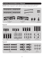
Accesorios y Partes Incluidas en el Empaque
IMPORTANTE: Asegúrese antes de instalar, de haber recibido todas las piezas de acuerdo a la lista de comprobación de
componentes. Si faltase cualquier parte o estuviese dañada, visite www.tripplite.com/support para solicitar servicio.
A
Placa de Pared
C
M5x8
D
Soporte Adaptador
Izquierdo
F
Seguros de Plástico
G
Candado de
Combinación
E
Soporte Adaptador
Derecho
B
Placa de Conexión
Paquete M
Paquete W
M-A
M5x14
M-E
M8x30
W-A
ST6.3x55
M-B
M6x14
M-F
Arandela
M-C
M8x20
M-G
Espaciador Pequeño
W-B
Taquete para Concreto
M-D
M6x30
M-H
Espaciador Grande
W-C
Arandela D6

19
Dimensiones del Producto
670 mm [26.4"]
670 mm [26.4"]
575 mm [22.6"]
525 mm [20.7"]
475 mm [18.7"]
425 mm [16.7"]
375 mm [14.8"]
325 mm [12.8"]
75 mm [3"]
125 mm 4.9"
175 mm [6.9"]
225 mm [8.9"]
275 mm [10.8"]
95 mm
[3.74"]
Mín: 200 mm [7.9"]
Máx: 418 mm [16.5"]
276 mm [10.9"]
304 mm [12"]
344 mm [13.5"]
416 mm [16.4"]
416 mm [16.4"]
524 mm [20"]
54 mm
[2.12"]
95 mm
[3.74"]
Mín: 200 mm [7.9"]
Máx: 600 mm [23.6"]

20
Ensamble
1
Fije las Placas de Conexión a las Placas de Pared
E
A
B
Utilizando los tornillos
M5x8 (E), fije las placas
de conexión a las placas
de pared.
La page est en cours de chargement...
La page est en cours de chargement...
La page est en cours de chargement...
La page est en cours de chargement...
La page est en cours de chargement...
La page est en cours de chargement...
La page est en cours de chargement...
La page est en cours de chargement...
La page est en cours de chargement...
La page est en cours de chargement...
La page est en cours de chargement...
La page est en cours de chargement...
La page est en cours de chargement...
La page est en cours de chargement...
La page est en cours de chargement...
La page est en cours de chargement...
La page est en cours de chargement...
La page est en cours de chargement...
La page est en cours de chargement...
La page est en cours de chargement...
La page est en cours de chargement...
La page est en cours de chargement...
La page est en cours de chargement...
La page est en cours de chargement...
La page est en cours de chargement...
La page est en cours de chargement...
La page est en cours de chargement...
La page est en cours de chargement...
La page est en cours de chargement...
La page est en cours de chargement...
La page est en cours de chargement...
La page est en cours de chargement...
La page est en cours de chargement...
La page est en cours de chargement...
La page est en cours de chargement...
La page est en cours de chargement...
La page est en cours de chargement...
La page est en cours de chargement...
La page est en cours de chargement...
La page est en cours de chargement...
La page est en cours de chargement...
La page est en cours de chargement...
La page est en cours de chargement...
La page est en cours de chargement...
La page est en cours de chargement...
La page est en cours de chargement...
La page est en cours de chargement...
La page est en cours de chargement...
La page est en cours de chargement...
La page est en cours de chargement...
La page est en cours de chargement...
La page est en cours de chargement...
La page est en cours de chargement...
La page est en cours de chargement...
La page est en cours de chargement...
-
 1
1
-
 2
2
-
 3
3
-
 4
4
-
 5
5
-
 6
6
-
 7
7
-
 8
8
-
 9
9
-
 10
10
-
 11
11
-
 12
12
-
 13
13
-
 14
14
-
 15
15
-
 16
16
-
 17
17
-
 18
18
-
 19
19
-
 20
20
-
 21
21
-
 22
22
-
 23
23
-
 24
24
-
 25
25
-
 26
26
-
 27
27
-
 28
28
-
 29
29
-
 30
30
-
 31
31
-
 32
32
-
 33
33
-
 34
34
-
 35
35
-
 36
36
-
 37
37
-
 38
38
-
 39
39
-
 40
40
-
 41
41
-
 42
42
-
 43
43
-
 44
44
-
 45
45
-
 46
46
-
 47
47
-
 48
48
-
 49
49
-
 50
50
-
 51
51
-
 52
52
-
 53
53
-
 54
54
-
 55
55
-
 56
56
-
 57
57
-
 58
58
-
 59
59
-
 60
60
-
 61
61
-
 62
62
-
 63
63
-
 64
64
-
 65
65
-
 66
66
-
 67
67
-
 68
68
-
 69
69
-
 70
70
-
 71
71
-
 72
72
-
 73
73
-
 74
74
-
 75
75


Tripp Lite DMVWSC4570XUL Le manuel du propriétaire
- Catégorie
- Supports muraux à panneau plat
- Taper
- Le manuel du propriétaire
dans d''autres langues
Documents connexes
-
Tripp Lite DWTSC3780MUL Manuel utilisateur
-
Tripp Lite DWFSC3780MUL Le manuel du propriétaire
-
Tripp Lite DWM3270XOUT Le manuel du propriétaire
-
-
-
-
-
-
-
Autres documents
-
Strong Carbon Series Manuel utilisateur
-
Kimex 031-4200K2 Guide d'installation
-
-
-
 SILVER MONKEY UT-800 TV Bracket Manuel utilisateur
-
-
-
 AmazonBasics PBH-994 Manuel utilisateur
-
-
Lindy Single Display Full Motion Wall Mount Manuel utilisateur

