Tripp Lite DMCVW4555X2 Le manuel du propriétaire
- Taper
- Le manuel du propriétaire

1
1111 W. 35th Street, Chicago, IL 60609 USA • www.tripplite.com/support
Copyright © 2019 Tripp Lite. All rights reserved.
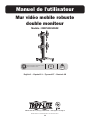
Owner’s Manual
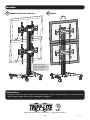
Heavy-Duty
Dual-Monitor Mobile Video Wall
Model: DMCVW4555X2
200x200 / 300x300 / 400x200
400x400 / 600x400
55"
MAX
132 lb. x 2
(60 kg) x 2
Español 13 • Français 25 • Русский 37 • Deutsch 49
WARRANTY REGISTRATION
Register your product today and be
automatically entered to win an ISOBAR
surge protector in our monthly drawing!
www.tripplite.com/warranty

2
NOTE: Read the entire instruction manual before you start assembly and installation.
Warranty and Product Registration
WARNING
• Do not begin the installation until you have read and understood the instructions and warnings contained in this manual. If
you have questions regarding any of the instructions or warnings, please visit www.tripplite.com/support.
• This product was designed to be installed and utilized ONLY as specified in this manual. Improper installation of this product
may cause damage or serious injury.
• This product should only be installed by someone of good mechanical ability, with basic building experience and a full
understanding of this instruction manual.
• Make sure the unit can safely support the combined load of the equipment and all attached hardware and components.
• Always use an assistant or mechanical lifting equipment to safely lift and position equipment.
• This product is intended for indoor use only. Using this product outdoors could lead to product failure and/or personal injury.
5-Year Limited Warranty
Seller warrants this product, if used in accordance with all applicable instructions, to be free from original defects in material and workmanship for a period of 5 years from the date
of initial purchase. If the product should prove defective in material or workmanship within that period, Seller will repair or replace the product, in its sole discretion.
THIS WARRANTY DOES NOT APPLY TO NORMAL WEAR OR TO DAMAGE RESULTING FROM ACCIDENT, MISUSE, ABUSE OR NEGLECT. SELLER MAKES NO EXPRESS WARRANTIES
OTHER THAN THE WARRANTY EXPRESSLY SET FORTH HEREIN. EXCEPT TO THE EXTENT PROHIBITED BY APPLICABLE LAW, ALL IMPLIED WARRANTIES, INCLUDING ALL WARRANTIES
OF MERCHANTABILITY OR FITNESS, ARE LIMITED IN DURATION TO THE WARRANTY PERIOD SET FORTH ABOVE; AND THIS WARRANTY EXPRESSLY EXCLUDES ALL INCIDENTAL AND
CONSEQUENTIAL DAMAGES. (Some states do not allow limitations on how long an implied warranty lasts, and some states do not allow the exclusion or limitation of incidental or
consequential damages, so the above limitations or exclusions may not apply to you. This warranty gives you specific legal rights, and you may have other rights which vary from
jurisdiction to jurisdiction).
WARNING: The individual user should take care to determine prior to use whether this device is suitable, adequate or safe for the use intended. Since individual applications are
subject to great variation, the manufacturer makes no representation or warranty as to the suitability or fitness of these devices for any specific application.
PRODUCT REGISTRATION
Visit www.tripplite.com/warranty today to register your new Tripp Lite product. You’ll be automatically entered into a drawing for a chance to win a FREE Tripp Lite product!*
* No purchase necessary. Void where prohibited. Some restrictions apply. See website for details.
Tripp Lite has a policy of continuous improvement. Specifications are subject to change without notice. Photos and illustrations may differ slightly from actual products.

3
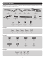
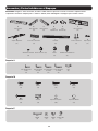
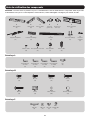
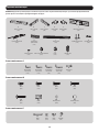
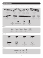
Component Checklist
IMPORTANT: Ensure you have received all parts according to the component checklist prior to installing. If any parts are missing
or faulty, visit www.tripplite.com/support for service.
A
Middle Base
(x1)
B
Left Base
(x1)
C
Right Base
(x1)
F
Universal Plate
(x2)
D
Left Cover
(x1)
E
Right Cover
(x1)
G
Adapter Bracket
(x4)
L
Cable Clamp
(x8)
M
Caster Wheel with Brake
(x2)
N
Caster Wheel
(x2)
O
Combo Lock
(x2)
H
Connecting Fitting
(x2)
I
Column
(x1)
J
Connecting Piece
(x1)
K
Top Cover
(x1)
Package M
Package A
Package P
M-A
M5x14
(x8)
M-B
M6x14
(x8)
M-C
M8x20
(x8)
M-D
M6x30
(x8)
M-E
M8x30
(x8)
M-F
Washer
(x8)
M-G
Small Spacer
(x16)
M-H
Big Spacer
(x8)
A-E
Wrench
(x1)
A-A
3 mm Hex Key
(x1)
A-B
4 mm Hex Key
(x1)
A-C
5 mm Hex Key
(x1)
A-D
6 mm Hex Key
(x1)
P-A
M8x65
(x8)
P-B
M8x16
(x4)
P-C
M8x35
(x4)
P-D
D8 Washer
(x4)

4
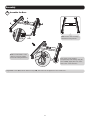
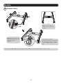
Assembly
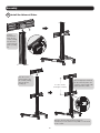
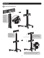
1
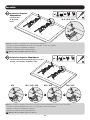
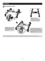
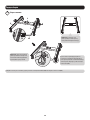
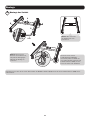
Assemble the Base
P-A
A-D
A-E
A
B
C
Note: Position base assembly
with wheels facing forward.
Note: Lock the brakes on the
casters to avoid any sudden
movements during installation.
Each caster can be adjusted
independently for fine tuning. Using the
wrench (A-E), slightly turn each caster
nut to lower or raise the base.
Using M8x65 screws (P-A) and the 6 mm hex key (A-D), attach the left and right base to the middle base.

5
Assembly
2
3
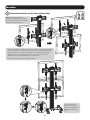
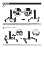
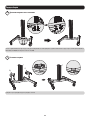
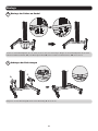
Attach the Columns to the Base
Install the Covers
Attach the left cover (D) and right cover (E) to the base.
Insert the connecting piece (J) into the column to attach the column to the base. Use M8x35 screws (P-C), D8 washers (P-D) and the
6 mm hex key (A-D) to secure the connecting piece and column to the base.
J
P-D
P-C
A-D
D
E

6
Assembly
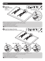
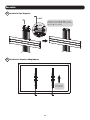
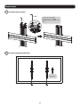
4
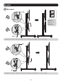
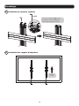
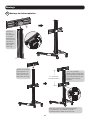
Install the Universal Plates
F
A-C
X + 0.2” (5 mm)
(X=Height of display)
Slide the
first universal
plate onto the
column, making
sure the arrow
on the universal
plate is pointing
up.
Slide the second
universal plate onto
the column, making
sure the arrow is
pointing up.
Allow enough space between
the two universal plates. Set
a distance of the height of the
display plus 0.2" (5 mm)
Once the universal plate positions have been
determined, use the 5 mm hex key (A-C) to secure them
to the column.

7
Assembly
5
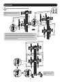
6
Install the Top Cover
Install the Adapter Brackets
Top of the
display.
K
P-B
A-D
Using M8x16 screws (P-B) and the
6 mm hex key (A-D), attach the
top cover (K) to the column.

8
Assembly
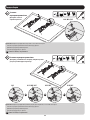
6a
6b
Install the
Adapter Brackets
For Flat
Back Screens
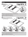
Install the Adapter Brackets
For Recessed Back Screen or to Access A/V Inputs
Note: Choose appropriate screws and spacers according to the type of screens.
• Position the adapter brackets as close as possible to the center of the display.
• Screw the adapter brackets onto the display.
• Repeat procedure for the second display.
Tighten all screws, but do not over-tighten.
Note: Choose appropriate screws, washers and spacers (if necessary) according to the type of screen.
• Position the adapter brackets as close as possible to the center of the display.
• Screw the adapter brackets onto the display.
• Repeat procedure for the second display.
Tighten all screws, but do not over-tighten.
M-A / M-B / M-C
M-F
M-C / M-D / M-E M-D / M-E M-D / M-E
M-C
M-F
or or or
M-F
M-G M-G
M-G
M-H M-H
M-F M-F

9
Assembly
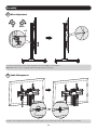
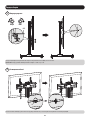
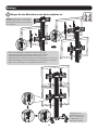
7
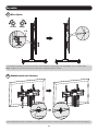
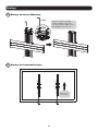
Attach the Displays onto the Universal Plates
O
Note: When installing the displays, make
sure to work from the bottom universal
plate to the top universal plate.
Use the combo locks (O)
to protect the displays
from tampering and theft.
• Using an assistant or mechanical lifting equipment, carefully lift the display and
pull down the two adapter bracket straps at the same time. Hook the display’s
adapter brackets over the top of the universal wall plate. Release the adapter
bracket straps to secure the display to the universal plate.
• Repeat procedure for the second display.

10
Assembly
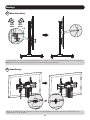
8
A-C
A-C
If the display tilts upward, adjust using the 5 mm hex key (A-C), as shown above.
If the display tilts downward, adjust using the 5 mm hex key (A-C), as shown above.
Note: Adjust the
angle of displays
in the order shown
above.
A-C
A-C
Micro-Adjustment

11
Assembly
8
9
Micro-Adjustment
Cable Management
To move the displays up or down, adjust using the 5 mm hex key (A-C), as shown above.
Note: Make sure to leave a 1 mm gap between the upper and lower displays.
Insert the cable clamps (L) horizontally into the universal plates’ slots, then turn the cable clamps vertically to secure them.
A-C
Up Down
1 mm
L

12
Assembly
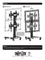
9
Cable Management
10
Adjustment
Run the cables
through the cable
clamps and the
column’s rubber strip.
Maintenance
• Check that the bracket is secure and safe to use at regular intervals (at least every three months).
• Please visit www.tripplite.com/support if you have any questions.
1111 W. 35th Street, Chicago, IL 60609 USA • www.tripplite.com/support
19-02-170 93-3950_RevA
+3°
–3°

13
1111 W. 35th Street, Chicago, IL 60609 EE UU • www.tripplite.com/support
Copyright © 2019 Tripp Lite. Todos los derechos reservados.
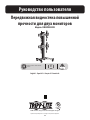
Manual del Propietario
Pared de Video Móvil de Doble
Monitor para Servicio Pesado
Modelo: DMCVW4555X2
200x200 / 300x300 / 400x200
400x400 / 600x400
55"
MÁXIMO
60 kg x 2
[132 lb] x 2
English 1 • Français 25 • Русский 37 • Deutsch 49

14
NOTA: Lea todo el manual de instrucciones antes de iniciar la instalación y ensamble.
Garantía
ADVERTENCIA
• No inicie la instalación hasta que haya leído y entendido las instrucciones y advertencias contenidas en este manual. Si
tiene preguntas con respecto a cualquiera de las instrucciones o advertencias, visite www.tripplite.com/support.
• Este producto fue diseñado para ser instalado y utilizado SOLAMENTE como se especifica en este manual. La instalación
incorrecta de este producto puede causar daños o lesiones severas.
• Este producto debe ser instalado únicamente por alguien con una buena habilidad mecánica, experiencia básica de
construcción y un entendimiento completo de este manual de instrucciones.
• Cerciórese que la unidad pueda soportar con seguridad la carga combinada de todo el hardware y componentes instalados.
• Utilice siempre un ayudante o equipo de elevación mecánico para levantar y colocar el equipo con seguridad.
• Este producto está diseñado para usarse sólo en interiores. Usar este producto en exteriores podría derivar en fallas del
producto y/o lesiones personales.
Garantía Limitada por 5 Años
El vendedor garantiza este producto, si se usa de acuerdo con todas las instrucciones aplicables, de que está libre de defectos en material y mano de obra por un período de 5
años a partir de la fecha de compra inicial. Si el producto resultara defectuoso en material o mano de obra dentro de ese período, el vendedor reparará o reemplazará el producto a
su entera discreción.
ESTA GARANTÍA NO SE APLICA AL DESGASTE NORMAL O A LOS DAÑOS QUE RESULTEN DE ACCIDENTES, USO INCORRECTO, USO INDEBIDO O NEGLIGENCIA. EL VENDEDOR NO
OTORGA GARANTÍAS EXPRESAS DISTINTAS A LA ESTIPULADA EN EL PRESENTE. SALVO EN LA MEDIDA EN QUE LO PROHÍBAN LAS LEYES APLICABLES, TODAS LAS GARANTÍAS
IMPLÍCITAS, INCLUYENDO TODAS LAS GARANTÍAS DE COMERCIALIZACIÓN O IDONEIDAD, ESTÁN LIMITADAS EN DURACIÓN AL PERÍODO DE GARANTÍA ESTABLECIDO; ASIMISMO,
ESTA GARANTÍA EXCLUYE EXPRESAMENTE TODOS LOS DAÑOS INCIDENTALES E INDIRECTOS. (Algunos estados no permiten limitaciones en cuanto a la duración de una garantía
y algunos estados no permiten la exclusión o limitación de daños incidentales o indirectos, de modo que las limitaciones anteriores pueden no aplicar para usted. Esta garantía le
otorga derechos legales específicos y usted puede tener otros derechos que pueden variar de una jurisdicción a otra).
ADVERTENCIA: antes de usarlo, cada usuario debe tener cuidado al determinar si este dispositivo es adecuado o seguro para el uso previsto. Ya que las aplicaciones individuales
están sujetas a gran variación, el fabricante no garantiza la adecuación de estos dispositivos para alguna aplicación específica.

15
Accesorios y Partes Incluidas en el Empaque
IMPORTANTE: Asegúrese antes de instalar, de haber recibido todas las piezas de acuerdo a la lista de comprobación de
componentes. Si faltase cualquier parte o estuviese dañada, visite www.tripplite.com/support para solicitar servicio.
A
Base Central
(x1)
B
Base Izquierda
(x1)
C
Base Derecha
(x1)
F
Placa Universal
(x2)
D
Tapa
Izquierda (x1)
E
Tapa
Derecha (x1)
G
Soporte Adaptador
(x4)
L
Abrazadera de Cable
(x8)
M
Rueda con Freno (x2)
N
Rueda
(x2)
O
Cerradura de Combinación
(x2)
H
Accesorio de Conexión
(x2)
I
Columna
(x1)
J
Pieza de Conexión
(x1)
K
Tapa Superior
(x1)
Paquete M
Paquete A
Paquete P
M-A
M5x14
(x8)
M-B
M6x14
(x8)
M-C
M8x20
(x8)
M-D
M6X30
(x8)
M-E
M8x30
(x8)
M-F
Arandela
(x8)
M-G
Espaciador Pequeño
(x16)
M-H
Espaciador Grande
(x8)
A-e
Llave
(x1)
A-A
Llave Hexagonal de
3 mm
(x1)
A-B
Llave Hexagonal
de 4 mm
(x1)
A-C
Llave Hexagonal
de 5 mm
(x1)
A-D
Llave Hexagonal
de 6 mm
(x1)
P-A
M8x65
(x8)
P-B
M8x16
(x4)
P-C
M8x35
(x4)
P-D
Arandela D8
(x4)

16
Ensamble
1
Ensamble la Base
P-A
A-D
A-E
A
B
C
Nota: Coloque el conjunto
de base con las ruedas hacia
adelante.
Nota: Bloquee los frenos en las
ruedas para evitar movimientos
repentinos durante la
instalación.
Cada rueda puede ajustarse
independientemente para un ajuste fino.
Gire ligeramente cada tuerca de rueda
con la llave (A-E) para bajar o elevar la
base.
Utilizando tornillos M8x65 (P-A) y la llave hexagonal de 6 mm (A-D), fije la base izquierda y derecha a la base central.

17
Ensamble
2
3
Fije las Columnas a la Base
Instale las Tapas
Fije la tapa izquierda D y la tapa derecha E a la base.
Inserte la pieza de conexión (J) en la columna para fijar la columna a la base. Utilice tornillos M8x35 (P-C ), arandelas D8 (P-D) y la
llave hexagonal de 6 mm (A-D) para fijar la pieza de conexión y la columna a la base.
J
P-D
P-C
A-D
D
E

18
Ensamble
4
Instale las Placas Universales
F
A-C
X + 5 mm [0.2”]
(X=Altura de pantalla)
Deslice la
primera placa
universal en
la columna,
asegurándose
de que la flecha
en la placa
universal esté
apuntando
hacia arriba.
Deslice la segunda
placa universal
en la columna,
asegurándose de
que la flecha esté
apuntando hacia
arriba.
Deje espacio suficiente entre
las dos placas universales.
Establezca una distancia de
la altura de la pantalla más 5
mm [0.2"]
Una vez que se han determinado las posiciones de la
placa universal, use la llave hexagonal de 5 mm (A-C)
para fijarlas a la columna.

19
Ensamble
5
6
Instale la Tapa Superior
Instale los Soportes Adaptadores
Parte superior
de la pantalla.
K
P-B
A-D
Utilizando Tornillos M8x16 (P-B) y la llave
hexagonal de 6 mm (a-D), coloque la tapa
superior (K) a la columna.

20
Ensamble
6a
6b
Instale los Soportes
Adaptadores
Para Pantallas
de Respaldo
Plano
Instale los Soportes Adaptadores
Para Pantalla con Parte Posterior Cóncava o para
Acceder a las Entradas de Audio y Video
Nota: Elija los tornillos y espaciadores de acuerdo al tipo de pantallas.
• Coloque los soportes adaptadores tan cerca como sea posible al centro de la pantalla.
• Atornille los soportes del adaptador a la pantalla.
• Repita el procedimiento para la segunda pantalla.
Apriete todos los tornillos pero no en exceso.
Nota: Elija los tornillos, arandelas y espaciadores (si fueran necesarios) apropiados de acuerdo al tipo de pantalla.
• Coloque los soportes adaptadores tan cerca como sea posible al centro de la pantalla.
• Atornille los soportes del adaptador a la pantalla.
• Repita el procedimiento para la segunda pantalla.
Apriete todos los tornillos pero no en exceso.
M-A / M-B / M-C
M-F
M-C / M-D / M-E M-D / M-E M-D / M-E
M-C
M-F
o o o
M-F
M-G M-G
M-G
M-H M-H
M-F M-F
La page est en cours de chargement...
La page est en cours de chargement...
La page est en cours de chargement...
La page est en cours de chargement...
La page est en cours de chargement...
La page est en cours de chargement...
La page est en cours de chargement...
La page est en cours de chargement...
La page est en cours de chargement...
La page est en cours de chargement...
La page est en cours de chargement...
La page est en cours de chargement...
La page est en cours de chargement...
La page est en cours de chargement...
La page est en cours de chargement...
La page est en cours de chargement...
La page est en cours de chargement...
La page est en cours de chargement...
La page est en cours de chargement...
La page est en cours de chargement...
La page est en cours de chargement...
La page est en cours de chargement...
La page est en cours de chargement...
La page est en cours de chargement...
La page est en cours de chargement...
La page est en cours de chargement...
La page est en cours de chargement...
La page est en cours de chargement...
La page est en cours de chargement...
La page est en cours de chargement...
La page est en cours de chargement...
La page est en cours de chargement...
La page est en cours de chargement...
La page est en cours de chargement...
La page est en cours de chargement...
La page est en cours de chargement...
La page est en cours de chargement...
La page est en cours de chargement...
La page est en cours de chargement...
La page est en cours de chargement...
-
 1
1
-
 2
2
-
 3
3
-
 4
4
-
 5
5
-
 6
6
-
 7
7
-
 8
8
-
 9
9
-
 10
10
-
 11
11
-
 12
12
-
 13
13
-
 14
14
-
 15
15
-
 16
16
-
 17
17
-
 18
18
-
 19
19
-
 20
20
-
 21
21
-
 22
22
-
 23
23
-
 24
24
-
 25
25
-
 26
26
-
 27
27
-
 28
28
-
 29
29
-
 30
30
-
 31
31
-
 32
32
-
 33
33
-
 34
34
-
 35
35
-
 36
36
-
 37
37
-
 38
38
-
 39
39
-
 40
40
-
 41
41
-
 42
42
-
 43
43
-
 44
44
-
 45
45
-
 46
46
-
 47
47
-
 48
48
-
 49
49
-
 50
50
-
 51
51
-
 52
52
-
 53
53
-
 54
54
-
 55
55
-
 56
56
-
 57
57
-
 58
58
-
 59
59
-
 60
60


Tripp Lite DMCVW4555X2 Le manuel du propriétaire
- Taper
- Le manuel du propriétaire
dans d''autres langues
Documents connexes
-
Tripp Lite DMCVW4555X4 Le manuel du propriétaire
-
-
-
-
-
-
-
-
-
Tripp Lite DWM3770PLX Le manuel du propriétaire