Tripp Lite DMCS60100XX Le manuel du propriétaire
- Taper
- Le manuel du propriétaire

1
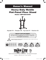
Owner’s Manual
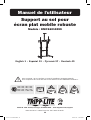
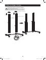
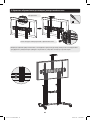
Heavy-Duty Mobile
Flat-Panel Floor Stand
Model: DMCS60100XX
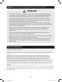
CAUTION: DO NOT EXCEED MAXIMUM LISTED WEIGHT CAPACITY. SERIOUS INJURY OR
PROPERTY DAMAGE MAY OCCUR!
1111 W. 35th Street, Chicago, IL 60609 USA • www.tripplite.com/support
Copyright © 2018 Tripp Lite. All rights reserved.
200 x 200 / 300 x 300 /
400 x 200 / 400 x 400 /
600 x 400 / 800 x 400 /
800 x 600 / 1000 x 600
100”
MAX
TV
220 lb.
(100 kg)
MAX
CAMERA
11 lb.
(5 kg)
MAX
DVD
11 lb.
(5 kg)
MAX
PROTECT YOUR INVESTMENT!
Register your product for quicker service and ultimate peace of mind.
You could also win an ISOBAR6ULTRA surge protector—a $100 value!
www.tripplite.com/warranty
Español 13 • Français 25 • Русский 37 • Deutsch 49
18-03-072-93380F.indb 1 4/30/2018 3:24:55 PM

2
NOTE: Read the entire instruction manual before you start assembly and installation.
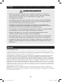
WARNING
• Do not begin the installation until you have read and understood the instructions
and warnings contained in this manual. If you have any questions regarding any
of the instructions or warnings, please visit www.tripplite.com/support
• This mounting bracket was designed to be installed and utilized ONLY as
specified in this manual. Improper installation of this product may cause damage
or serious injury.
• This product should only be installed by someone of good mechanical ability,
with basic building experience and a full understanding of this instruction
manual.
• Make sure that the mounting surface can safely support the combined load of
the equipment and all attached hardware and components.
• Always use an assistant or mechanical lifting equipment to safely lift and position
equipment.
• Tighten screws firmly, but do not over-tighten. Over-tightening screws can
damage the items, greatly reducing their holding power.
• This product is intended for indoor use only. Using this product outdoors could
lead to product failure and personal injury.
Warranty & Product Registration
5-Year Limited Warranty
Seller warrants this product, if used in accordance with all applicable instructions, to be free from original defects
in material and workmanship for a period of 5 years from the date of initial purchase. If the product should
prove defective in material or workmanship within that period, Seller will repair or replace the product, in its sole
discretion.
THIS WARRANTY DOES NOT APPLY TO NORMAL WEAR OR TO DAMAGE RESULTING FROM ACCIDENT, MISUSE,
ABUSE OR NEGLECT. SELLER MAKES NO EXPRESS WARRANTIES OTHER THAN THE WARRANTY EXPRESSLY
SET FORTH HEREIN. EXCEPT TO THE EXTENT PROHIBITED BY APPLICABLE LAW, ALL IMPLIED WARRANTIES,
INCLUDING ALL WARRANTIES OF MERCHANTABILITY OR FITNESS, ARE LIMITED IN DURATION TO THE WARRANTY
PERIOD SET FORTH ABOVE; AND THIS WARRANTY EXPRESSLY EXCLUDES ALL INCIDENTAL AND CONSEQUENTIAL
DAMAGES. (Some states do not allow limitations on how long an implied warranty lasts, and some states do not
allow the exclusion or limitation of incidental or consequential damages, so the above limitations or exclusions
may not apply to you. This warranty gives you specific legal rights, and you may have other rights which vary from
jurisdiction to jurisdiction).
WARNING: The individual user should take care to determine prior to use whether this device is suitable, adequate
or safe for the use intended. Since individual applications are subject to great variation, the manufacturer makes
no representation or warranty as to the suitability or fitness of these devices for any specific application.
PRODUCT REGISTRATION
Visit www.tripplite.com/warranty today to register your new Tripp Lite product. You’ll be automatically entered into a
drawing for a chance to win a FREE Tripp Lite product!*
* No purchase necessary. Void where prohibited. Some restrictions apply. See website for details.
Tripp Lite has a policy of continuous improvement. Specifications are subject to change without notice.
18-03-072-93380F.indb 2 4/30/2018 3:24:55 PM

3
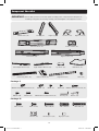
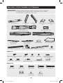
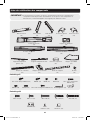
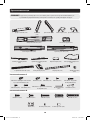
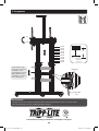
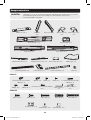
Component Checklist
IMPORTANT: Ensure that you have received all parts according to the component checklist prior to
installing. If any parts are missing or faulty, visit www.tripplite.com/support for service.
Middle Base (x1)
M5 x 14 (x4) M8 x 50 (x4)
Left Column (x1)
Right Adapter Bracket (x1)
Camera Shelf (x1)
Plastic Handle (x2)
Right Column (x1)
Top Cover (x2)
Support Bar (x1)
DVD Shelf (x1)
Knob (x2)
Left Adapter Bracket (x1)
Connecting Plate (x1)
M6x25 Philips Rounded Head (x2)
M6x25 Hex Rounded Head (x2)
M6x16 (x4)
Hex Key (x1)
M4x6 (x3)
Wrench (x1)
M4x6 (x2) M6x25 Hex Socket Head (x2)
M6x14 (x6) M8x25 (x8)
Left Leg (x1) Right Leg (x1)
M6 x 14 x4)
Washer (x4) Small Spacer (x8)
M6 x 30 (x4)
Big Spacer (x8)
M8 x 30 (x4)
Left Cover (x1) Right Cover (x1)
Universal Plate (x1)
Package M
Package P
18-03-072-93380F.indb 3 4/30/2018 3:24:55 PM

4
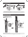
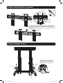
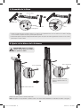
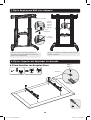
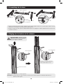
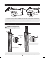
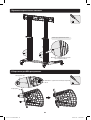
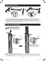
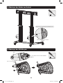
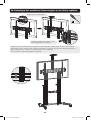
1. Assembling the Base
2. Adjust Column Height
• Insert the right leg into the base. Align the holes in the right leg to the holes in the base. Secure with the
screws. Repeat this step for the left leg.
• Each caster can be adjusted independently for fine tuning. Slightly turn the nut to lower or raise the base.
Repeat this step for the left column.
Note: Make sure both columns are at the same height using the height indicator as guide.
Adjust to the desired height,
then tighten all screws.
CAUTION: Hold the inner column
when loosening the screws to
adjust height.
Middle Base
Left Leg
M6x16
Hex Key
Right Leg
Wrench
Hex Key
Hex Key
Right Column
18-03-072-93380F.indb 4 4/30/2018 3:24:57 PM

5
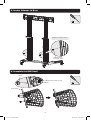
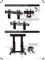
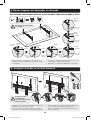
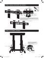
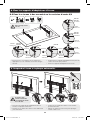
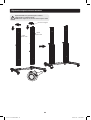
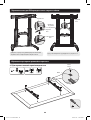
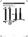
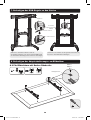
3. Attach Columns to Base
During this step, the columns are not
secured to the base with screws.
Be careful not to knock the columns over.
Right Column
Left Column
Plastic Handle
18-03-072-93380F.indb 5 4/30/2018 3:24:58 PM

6
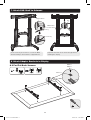
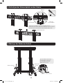
4. Attach Universal Plate to Columns
5. Secure Columns to Base
M6x14
Top Cover
Universal
Plate
Universal
Plate
Support
Insert the Universal Plate’s Supports into the column along
the column rails. Tighten all screws with a suitable Philips
screwdriver.
Using the Hex Key, tighten the
screws to secure the columns
to the base.
Left Cover
Right
Cover
M8x25 Hex Key
18-03-072-93380F.indb 6 4/30/2018 3:25:00 PM

7
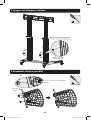
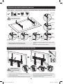
5. Secure Columns to Base
6. Assemble the DVD Shelf
M6x25 Philips
Rounded Head
Tighten the safety screws.
Knob
Support Bar
M6x14
M6x25 Hex Rounded Head
18-03-072-93380F.indb 7 4/30/2018 3:25:02 PM

8
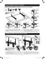
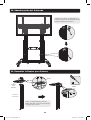
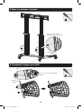
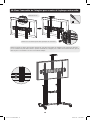
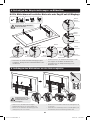
7. Attach DVD Shelf to Columns
8. Attach Adapter Brackets to Display
Use the Hex Key and screws to secure the DVD
Shelf Assembly to the Columns’ Support Blocks.
Adjust the Columns to the desired height before
installing the display.
Hex Key
8.1 For Flat Back Screens
Hex Key
Hex
Key
Support Block
M6x25 Hex
Socket Head
M5x14
M6x14
Washer
TV
TV
TV
18-03-072-93380F.indb 8 4/30/2018 3:25:04 PM

9
8. Attach Adapter Brackets to Display
9. Hang the Display onto the Universal Plate
8.2 For Recessed Back Screens or Access to A/V Inputs
• Choose the appropriate screws, washers and
spacers (if necessary) according to the type of
screen.
• Position the adapter brackets as close as possible
to the center of the display.
• Screw the adapter brackets onto the display.
• Hook the adapter brackets (attached to the display)
onto the universal plate.
• Rotate the bottom screws counterclockwise to lock.
• Rotate the bottom screws clockwise to unlock.
• Use a padlock (not included) to prevent display
from being stolen.
Do not over-tighten
screws.
M6x30
M8x30
M6x30
M8x30
M6x30
M8x30
M8x50
M8x50
M8x50
Washer Washer Washer Washer
Washer
Washer
Small
Spacer
Small
Spacer
Small
Spacer
Small
Spacer
Big
Spacer
Big
Spacer
Big
Spacer
Big
Spacer
Big
Spacer
or or or
or
or
Make sure the display
is correctly mounted
before releasing the
display.
18-03-072-93380F.indb 9 4/30/2018 3:25:06 PM

10
C
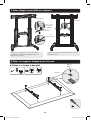
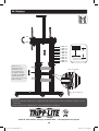
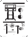
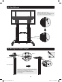
10. Cable Management
11. Assemble the Camera Shelf
Route the power and connection cables
through the openings on the Left and
Right Columns.
Use a Philips screwdriver and screws
to attach the Camera Shelf to the
Connecting Plate.
Camera
Shelf
Connecting
Plate
M4x6
M4x6
18-03-072-93380F.indb 10 4/30/2018 3:25:08 PM

11
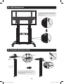
12. Attach the Camera Shelf Assembly to the Universal Plate
Remove the Universal Plate’s two rear screws, then attach the Camera Shelf Assembly using the same screws
just removed. Adjust the Camera Shelf Assembly to the desired height, then secure by tightening the screws
with a Philips screwdriver.
Remove Screws
Insert Removed Screws to attach Connecting Plate
18-03-072-93380F.indb 11 4/30/2018 3:25:09 PM

12
1111 W. 35th Street, Chicago, IL 60609 USA • www.tripplite.com/support
Maintenance
• Check that the bracket is secure and safe to use at regular intervals (at least every three months).
• For any additional questions, visit www.tripplite.com/support.
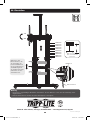
+5°
–10°
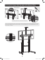
13. Adjustment
Support Block
TV panel center
height measured
from floor.
1200 mm
1250 mm
1300 mm
1350 mm
1400 mm
1450 mm
1500 mm
1550 mm
1600 mm
1650 mm
Hex Key
Use the Hex Key to
loosen the screws on
both support blocks.
Adjust the DVD shelf
to the desired height,
then tighten screws to
secure.
18-03-072-93380F.indb 12 4/30/2018 3:25:11 PM

13
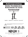
Manual del Propietario
Pedestal Móvil de Piso de Servicio
Pesado para Panel Plano
Modelo: DMCS60100XX
PRECAUCIÓN: NO EXCEDA LA CAPACIDAD MÁXIMA DE LA CARGA INDICADA. ¡PUEDEN
OCURRIR LESIONES SEVERAS O DAÑOS A LA PROPIEDAD!
1111 W. 35th Street, Chicago, IL 60609 EE. UU. • www.tripplite.com/support
Copyright © 2018 Tripp Lite. Todos los derechos reservados.
200 x 200 / 300 x 300 /
400 x 200 / 400 x 400 /
600 x 400 / 800 x 400 /
800 x 600 / 1000 x 600
100”
MÁXIMO
TV
[220 lb]
100 kg
MÁXIMO
CÁMARA
[11 lb]
5 kg
MÁXIMO
DVD
[11 lb]
5 kg
MÁXIMO
English 1 • Français 25 • Русский 37 • Deutsch 49
18-03-072-93380F.indb 13 4/30/2018 3:25:11 PM

14
NOTA: Lea todo el manual de instrucciones antes de iniciar la instalación y ensamble.
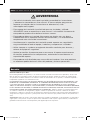
ADVERTENCIA
• No inicie la instalación hasta que haya leído y entendido las instrucciones
y advertencias contenidas en este manual. Si tiene cualquier pregunta con
respecto a cualquiera de las instrucciones o advertencias, visite
www.tripplite.com/support.
• Este soporte de instalación fue diseñado para ser instalado y utilizado
SOLAMENTE como se especifica en este manual. La instalación incorrecta de
este producto puede causar daños o lesiones severas.
• Este producto debe ser instalado únicamente por alguien con una buena
habilidad mecánica, experiencia básica de construcción y un entendimiento
completo de este manual de instrucciones.
• Cerciórese que la superficie de instalación pueda soportar con seguridad la
carga combinada de todo el equipo, hardware y componentes instalados.
• Utilice siempre un ayudante o equipo de elevación mecánico para levantar y
colocar el equipo con seguridad.
• Apriete los tornillos firmemente pero no en exceso. Al apretar excesivamente
los tornillos puede dañar los componentes, reduciendo sustancialmente su
capacidad de soporte.
• Este producto está diseñado para usarse sólo en interiores. Usar este producto
en exteriores podría derivar en fallas del producto y lesiones personales.
Garantía
Garantía Limitada por 5 Años
El vendedor garantiza este producto, si se usa de acuerdo con todas las instrucciones aplicables, de que está
libre de defectos en material y mano de obra por un período de 5 años a partir de la fecha de compra inicial.
Si el producto resultara defectuoso en material o mano de obra dentro de ese período, el vendedor reparará o
reemplazará el producto a su entera discreción.
ESTA GARANTÍA NO SE APLICA AL DESGASTE NORMAL O A LOS DAÑOS QUE RESULTEN DE ACCIDENTES, USO
INCORRECTO, USO INDEBIDO O NEGLIGENCIA. EL VENDEDOR NO OTORGA GARANTÍAS EXPRESAS DISTINTAS
A LA ESTIPULADA EN EL PRESENTE. SALVO EN LA MEDIDA EN QUE LO PROHÍBAN LAS LEYES APLICABLES,
TODAS LAS GARANTÍAS IMPLÍCITAS, INCLUYENDO TODAS LAS GARANTÍAS DE COMERCIALIZACIÓN O IDONEIDAD,
ESTÁN LIMITADAS EN DURACIÓN AL PERÍODO DE GARANTÍA ESTABLECIDO; ASIMISMO, ESTA GARANTÍA EXCLUYE
EXPRESAMENTE TODOS LOS DAÑOS INCIDENTALES E INDIRECTOS. (Algunos estados no permiten limitaciones
en cuanto a la duración de una garantía y algunos estados no permiten la exclusión o limitación de daños
incidentales o indirectos, de modo que las limitaciones anteriores pueden no aplicar para usted. Esta garantía le
otorga derechos legales específicos y usted puede tener otros derechos que pueden variar de una jurisdicción a
otra).
ADVERTENCIA: Antes de usarlo, cada usuario debe tener cuidado al determinar si este dispositivo es adecuado o
seguro para el uso previsto. Ya que las aplicaciones individuales están sujetas a gran variación, el fabricante no
garantiza la adecuación de estos dispositivos para alguna aplicación específica.
18-03-072-93380F.indb 14 4/30/2018 3:25:11 PM

15
Accesorios y Partes Incluidas en el Empaque
IMPORTANTE: Asegúrese de haber recibido todas las partes de acuerdo a la lista de comprobación
de componentes antes de instalar. Si faltase cualquier parte o estuviese dañada,
visite www.tripplite.com/support para solicitar servicio.
Base Central (x1)
M5 x 14 (x4) M8 x 50 (x4)
Columna Izquierda (x1)
Soporte Adaptador
Derecho (x1)
Repisa para Cámara (x1)
Manija de Plástico (x2)
Columna Derecha (x1)
Tapa Superior (x2)
Barra de Soporte (x1)
Repisa para DVD (x1)
Perilla (x2)
Soporte Adaptador
Izquierdo (x1)
Placa de Conexión (x1)
M6x25 Philips de Cabeza Redonda
(x2)
M6x25 Allen de
Cabeza Redonda (x2)
M6x16 (x4)
Llave Hexagonal (x1)
M4x6 (x3)
Llave (x1)
M4x6 (x2) Tornillos Allen de Cabeza
Hueca M6x25 (x2)
M6x14 (x6) M8x25 (x8)
Pata Izquierda
(x1)
Pata Derecha
(x1)
M6 x 14 (x4)
Arandela (x4) Espaciador
Pequeño (x8)
M6 x 30 (x4)
Espaciador
Grande (x8)
M8 x 30 (x4)
Cubierta Izquierda
(x1)
Cubierta Derecha
(x1)
Placa Universal (x1)
Paquete M
Paquete P
18-03-072-93380F.indb 15 4/30/2018 3:25:11 PM

16
1. Ensamble de la Base
2. Ajuste de la Altura de la Columna
• Inserte la pata derecha en la base. Alinee los orificios en la pata derecha con los orificios en la base. Asegure
con los tornillos. Repita este paso para la pata izquierda.
• Cada rueda puede ajustarse independientemente para un ajuste fino. Gire ligeramente la tuerca con la llave
para bajar o elevar la base.
Repita este paso para la columna izquierda.
Nota: Asegúrese de que ambas columnas estén a la misma altura utilizando el indicador de altura como guía.
Ajuste a la altura deseada,
entonces apriete todos los
tornillos.
PRECAUCIÓN: Sujete la columna
interna cuando afloje los tornillos
para ajustar la altura.
Base Central
Pata Izquierda
M6x16
Llave Hexagonal
Pata Derecha
Llave
Llave Hexagonal
Llave Hexagonal
Columna Derecha
18-03-072-93380F.indb 16 4/30/2018 3:25:13 PM

17
3. Fije las Columnas a la Base
Durante este paso, las columnas no
se sujetan a la base con tornillos.
Tenga cuidado de no dejar caer las columnas.
Columna Derecha
Columna
Izquierda
Manija de Plástico
18-03-072-93380F.indb 17 4/30/2018 3:25:14 PM

18
4. Coloque la placa Universal en las Columnas
5. Asegure las Columnas a la Base
M6x14
Tapa Superior
Placa
Universal
Soporte
para Placa
Universal
Inserte los soportes de la Placa Universal en la columna a lo
largo de los rieles de la columna. Apriete todos los tornillos
con un desatornillador Philips adecuado.
Usando la llave hexagonal,
apriete los tornillos para fijar
las columnas a la base.
Cubierta Izquierda
Cubierta
Derecha
M8x25 Llave
Hexagonal
18-03-072-93380F.indb 18 4/30/2018 3:25:15 PM

19
5. Asegure las Columnas a la Base
6. Ensamble la Repisa para DVD
M6x25 Philips de
Cabeza Redonda
Apriete los tornillos de seguridad.
Perilla
Barra de
Soporte
M6x14
Allen de Cabeza Redonda M6x25
18-03-072-93380F.indb 19 4/30/2018 3:25:17 PM

20
7. Fije la Repisa para DVD a las columnas
8. Fije los Soportes del Adaptador a la Pantalla
Utilice la llave y tornillos Allen para fijar al
Conjunto de Repisa de DVD a los Bloques de
Soporte de las Columnas.
Ajuste las columnas a la altura deseada antes de
instalar la pantalla.
Llave
Hexagonal
8.1 Para Pantallas con Respaldo Plano
Llave
Hexagonal
Llave
Hexagonal
Bloque de Soporte
Tornillos
Allen de
Cabeza
Hueca
M6x25
M5x14
M6x14
Arandela
TV
TV
TV
18-03-072-93380F.indb 20 4/30/2018 3:25:19 PM
La page est en cours de chargement...
La page est en cours de chargement...
La page est en cours de chargement...
La page est en cours de chargement...
La page est en cours de chargement...
La page est en cours de chargement...
La page est en cours de chargement...
La page est en cours de chargement...
La page est en cours de chargement...
La page est en cours de chargement...
La page est en cours de chargement...
La page est en cours de chargement...
La page est en cours de chargement...
La page est en cours de chargement...
La page est en cours de chargement...
La page est en cours de chargement...
La page est en cours de chargement...
La page est en cours de chargement...
La page est en cours de chargement...
La page est en cours de chargement...
La page est en cours de chargement...
La page est en cours de chargement...
La page est en cours de chargement...
La page est en cours de chargement...
La page est en cours de chargement...
La page est en cours de chargement...
La page est en cours de chargement...
La page est en cours de chargement...
La page est en cours de chargement...
La page est en cours de chargement...
La page est en cours de chargement...
La page est en cours de chargement...
La page est en cours de chargement...
La page est en cours de chargement...
La page est en cours de chargement...
La page est en cours de chargement...
La page est en cours de chargement...
La page est en cours de chargement...
La page est en cours de chargement...
La page est en cours de chargement...
-
 1
1
-
 2
2
-
 3
3
-
 4
4
-
 5
5
-
 6
6
-
 7
7
-
 8
8
-
 9
9
-
 10
10
-
 11
11
-
 12
12
-
 13
13
-
 14
14
-
 15
15
-
 16
16
-
 17
17
-
 18
18
-
 19
19
-
 20
20
-
 21
21
-
 22
22
-
 23
23
-
 24
24
-
 25
25
-
 26
26
-
 27
27
-
 28
28
-
 29
29
-
 30
30
-
 31
31
-
 32
32
-
 33
33
-
 34
34
-
 35
35
-
 36
36
-
 37
37
-
 38
38
-
 39
39
-
 40
40
-
 41
41
-
 42
42
-
 43
43
-
 44
44
-
 45
45
-
 46
46
-
 47
47
-
 48
48
-
 49
49
-
 50
50
-
 51
51
-
 52
52
-
 53
53
-
 54
54
-
 55
55
-
 56
56
-
 57
57
-
 58
58
-
 59
59
-
 60
60


Tripp Lite DMCS60100XX Le manuel du propriétaire
- Taper
- Le manuel du propriétaire
dans d''autres langues
Documents connexes
-
Tripp Lite TRIPP-LITE DMCS60100XX Heavy-Duty Mobile Flat-Panel Floor Stand Le manuel du propriétaire
-
-
-
-
-
-
-
-
Tripp Lite DWM60100XX Le manuel du propriétaire
-
