PROPANE CONSTRUCTION
CONVECTION HEATER
OWNER’S MANUAL
VARIABLE 40-80,000 BTU/HR
75-200,000 BTU/HR
MODELS
PCC80V, PCC200V
IMPORTANT: Read and understand this manual before
assembling, starting or servicing heater. Improper use
of heater can cause serious injury. Keep this manual for
future reference.
GENERAL HAZARD WARNING:
Failure to comply with the precautions and instructions
provided with this heater, can result in death, serious
bodily injury and property loss or damage from hazards
of re, explosion, burn, asphyxiation, carbon monoxide
poisoning and/or electrical shock.
Only persons who can understand and follow the in-
structions should use or service this heater.
If you need assistance or heater information such as an
instructions manual, labels, etc. contact the manufacturer.
Questions, problems, missing parts? Before returning to your retailer, call
our customer service department at 1-866-573-0674, 7:30 am - 4:15 pm CST,
Monday through Friday or email customerservice@usaprocom.com

www.usaprocom.com
160311-01B2
SAFETY
SPECIFICATIONS
80,000 Btu 200,000 Btu
Type of Gas Propane/LP Only Propane/LP Only
Rating 40,000 - 80,000 Btu/hr
(11.7 - 23.4 kW)
75,000 - 200,000 Btu/hr
(22.0 - 58.6 kW)
Gas Supply Pressure to regulator Max: Tank Pressure Max: Tank Pressure
Min: 1 psig (6.89 kPa) Min: 15 psig (103 kPa)
Gas Supply Pressure Regulator Out 22" (55.9 cm) W.C. 10 psig (68.9 kPa)
Ignition Piezo Ignitor Piezo Ignitor
Minimum Ambient Temp. Rating 0° F (-17.8° C) 0° F (-17.8° C)
Fuel Consumption 1.85 - 3.7 lb/hr
(0.84 – 1.63 kg/hr)
3.5 - 9.2 lb/hr
(1.57 - 4.2 kg/hr)
Fuel Orice Port No. 6 6
Fuel Orice Port Size 0.041" (1.04 mm) 0.032" (0.81 mm)
WARNING: This product
contains and/or generates
chemicals known to the State
of California to cause cancer or
birth defects or other reproduc-
tive harm.
WARNING: Fire, burn inha-
lation and explosion hazard.
Keep solid combustibles, such
as building materials, paper or
cardboard, a safe distance away
from the heater as recommended
by the instructions. Never use
the heater in spaces which do or
may contain volatile or airborne
combustibles or products such
as gasoline, solvents, paint thin-
ner, dust particles or unknown
chemicals.
WARNING: Not for home or
recreational vehicle use.
The heater is designed for use as a construc-
tion heater in accordance with ANSI Z83.7/
CGA 2.14. Other standards govern the use of
fuel gases and heating products for specic
uses. Your local authority can advise you
about these. The primary purpose of construc-
tion heaters is to provide temporary heating
of buildings under construction, alteration or
repair. Properly used, the heater provides safe
economical heating. Products of combustion
are vented into the area being heated.
We cannot foresee every use which may be
made of our heaters. CHECK WITH YOUR
LOCAL FIRE SAFETY AUTHORITY IF YOU
HAVE QUESTIONS ABOUT HEATER USE.
Other standards govern the use of fuel gas-
es and heat producing products for specic
uses. Your local authorities can advise you
about these.
TABLE OF CONTENTS
Specications ............................................ 2
Safety ........................................................ 2
Unpacking.................................................. 4
Theory of Operation................................... 4
Product Identication ................................. 4
Ventilation ................................................. 4
Propane Supply ......................................... 5
Installation ................................................. 5
Operation ................................................... 6
Storage ...................................................... 8
Maintenance .............................................. 8
Technical Services ..................................... 8
Accessories ............................................... 8
Troubleshooting ......................................... 9
Replacement Parts .................................... 9
Parts ........................................................ 10
Warranty .................................................. 12

www.usaprocom.com
3160311-01B
SAFETY
DANGER: Carbon monoxide
poisoning may lead to death!
Carbon Monoxide Poisoning: Some peo-
ple are more affected by carbon monoxide
than others. Early signs of carbon monoxide
poisoning resemble the flu, with headaches,
dizziness and/or nausea. If you have these
signs, the heater may not be working prop-
erly. Get fresh air at once! Check for proper
ventilation and have heater serviced.
Propane Gas: Propane gas is odorless. An
odor-making agent is added to propane gas.
The odor helps you detect a propane gas
leak. However, the odor added to propane
gas may fade. Propane gas may be present
even though no odor exists.
Make certain you read and understand all
warnings. Keep this manual for reference. It
is your guide to safe and proper operation of
this heater.
For use with Propane/LP gas only.
1. Install and use heater with care. Follow
all local ordinances and codes. In the ab-
sence of local ordinances and codes, refer
to the Standard for Storage and Handling
of Liqueed Petroleum Gas, ANSI/NFPA
58 and the Natural Gas and Propane
Installation Code, CAN/CGA B149.1. This
instructs on the safe storage and handling
of propane gases.
2. This product has been approved for use
in the Commonwealth of Massachusetts.
3. Use only propane gas set up for vapor
withdrawal.
4. Provide adequate ventilation. Before us-
ing heater, provide at least a 2.5 square
foot (0.232 m
2
) (80,000 BTU heaters) or
6.0 square foot (0.557 m
2
) (200,000 BTU
heaters) opening of fresh, outside air.
5. For indoor use only. Adequate ventilation
must be provided. Do not use heater
outdoors.
6. Keep heater away from strong drafts,
wind, water spray, rain or dripping water.
7. Do not use heater in occupied dwellings
or in living or sleeping quarters.
8. Do not use heater in a basement or below
ground level. Propane gas is heavier than
air. If a leak occurs, propane gas may sink
to the lowest possible level.
9. Keep appliance area clear and free from
combustible materials, gasoline, paint
thinner and other flammable vapors and
liquids. Dust is combustible. Do not use
heater in areas with high dust content.
10. Minimum heater clearances from com-
bustibles:
80,000 Btu heaters
Sides: 3 feet (91 cm); Top: 6 feet (1.83 m)
200,000 Btu heaters
Sides: 3 feet (91 cm); Top: 7 feet (2.1 m)
Locate 10 ft. (3 m) from canvas or plastic
tarpaulins or similar coverings and secure
them to prevent flapping or movement due
to wind action.
11. Keep heater at least 6 feet (1.83 m) from
propane tank(s) in USA or 10 feet (3 m)
from propane tank(s) in Canada.
12. Keep propane tank(s) below 100° F
(37.8°C).
13. Use only the hose and factory preset
regulator provided with the heater.
14. Check heater for damage before each
use. Do not use a damaged heater.
15. Check hose before each use of heater.
If highly worn or cut, replace with hose
specied by manufacturer before using
heater.
16. Do not alter heater. Keep heater in its
original state.
17. Do not use heater if altered.
18. Locate heater on a stable and level surface.
Do not move while heater is hot or running.
Position heater properly before use.
19. Not intended for use on nished floors.
20. Never block air inlet (bottom of shell) or
air outlet (around top of shell) of heater.
21. Do not leave heater unattended.
22. Keep children and animals away from
heater.
23. Never move, handle or service a hot
or operating heater. Severe burns may
result. You must wait 15 minutes after
turning heater off.
24. To prevent injury, wear gloves when han-
dling heater.
25. Never attach duct work to heater.
26. Turn off propane supply to heater when
not in use.

www.usaprocom.com
160311-01B4
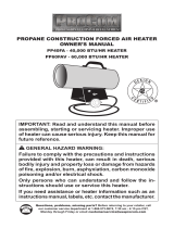
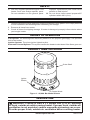
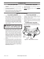
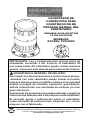
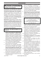
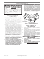
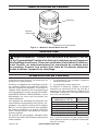
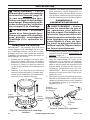
Outer Shell
Ignitor
Button
Control Knob
Figure 1 - 80,000 Btu Model Shown
UNPACKING
1. Remove all packing items applied to heater for shipment. Keep plastic cover caps (attached
to inlet connector and hose/regulator assembly) for storage.
2. Remove all items from carton.
3. Check all items for shipping damage. If heater is damaged, promptly inform dealer where
you bought heater.
VENTILATION
WARNING: Provide at least a 2.5 square foot (0.23 m
2
) opening
of fresh, outside air while running heater. If proper fresh, outside air
ventilation is not provided, carbon monoxide poisoning can occur.
Provide proper fresh, outside air ventilation before running heater.
THEORY OF OPERATION
Fuel System: The hose/regulator assembly attaches to the propane gas supply. This provides
fuel to the heater.
Ignition System: The piezo ignitor lights the pilot.
Automatic Control System: This system causes the heater to shut down if the flame goes out.
PRODUCT IDENTIFICATION
SAFETY
27. Use only original replacement parts. This
heater must use design-specic parts.
Do not substitute or use generic parts.
Improper replacement parts could cause
serious or fatal injuries.
28. Do not direct heat toward propane/LP
cylinders within 20 ft (6 m).

www.usaprocom.com
5160311-01B
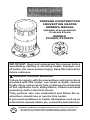
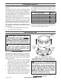
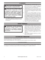
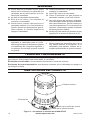
INSTALLATION
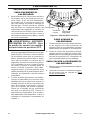
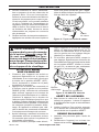
Figure 2 - Lifting Outer Shell
Screw,
Install
Last
Screw,
Install
First
Outer
Shell
PROPANE SUPPLY
You must provide propane gas and propane
tank(s).
Use this heater only with a propane vapor
withdrawal supply system. See Chapter 5
of the Standard for Storage and Handling of
Liqueed Petroleum Gas, ANSI/NFPA 58 and/
or CAN/CGA B149.2. Your local library or re
department will have this booklet.
This heater will operate with a 20-pound (9,07
kg) propane tank. However, you can only
operate it in the LOW position during mildly
cool weather. At higher heat settings or during
colder weather, you must use larger tanks.
The amount of propane gas ready for use
from propane tanks varies. Two factors decide
this amount.
1. The amount of propane gas in tank(s)
2. The temperature of tank(s)
The chart below shows the minimum number
of 100-pound (45 kg) tanks needed to run
the heater. Connect tanks together with a
manifold.
Average Temperature °F (°C)
At Tank Location
Number
Of Tanks
80,000 Btu models
20° (-6.7°) to 60° (15,6°) 1
0° (-17,8°) to 20° (-6.7°) 2
200,000 Btu models
20° (-6.7°) to 60° (15,6°) 2
0° (-17,8°) to 20° (-6.7°) 3
Less gas is vaporized at lower temperatures.
Your local propane gas dealer will help you
select the proper supply system.
WARNING: Review and un-
derstand the warnings in Safety,
page 2. They are needed to safely
operate this heater. Follow all lo-
cal codes when using this heater.
CAUTION: Never ignite and/
or run this heater unless the
shells are fully extended and
locked into position.
OUTER SHELL
IMPORTANT: When the heater is rst re-
moved from carton, the outer shell is in the
down position. Protect hands before lifting
outer shell. Never grasp bare metal without
hand protection.
1. Care must be taken to protect hands
during this step. Lift outer shell straight
up as shown in Figure 2, until screw holes
line up and slotted holes are visable.
2. Install 3 screws in lower holes as shown
in Figure 2. Let upper shell rest on lower
screws. Holes and slots will line up.
3. Install 3 screws into upper holes to secure
upper shell. The heater must not be op-
erated unless the outer shell is properly
extended and fully secured into place.
CONNECTING TO GAS SUPPLY
WARNING: Test all gas piping
and connections for leaks after
installation or servicing. Never
use an open ame to check for
a leak. Apply a mixture of liquid
soap and water to all joints.
Bubbles forming show a leak.
Correct all leaks at once.
1. Provide propane supply system (see
Propane Supply, above).

www.usaprocom.com
160311-01B6
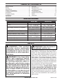
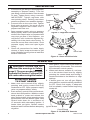
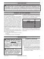
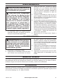
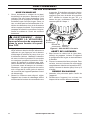
Figure 3 - Regulator Position
Propane
Tank
Propane Supply
Valve
Regulator
Hose
POL
Fitting
INSTALLATION
Figure 4 - Hose and Valve Inlet
Hose
Valve Inlet
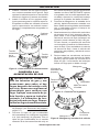
OPERATION
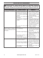
Figure 5 - 80,000 BTU Controls
Ignitor Button
Control Knob
2. Connect fuel gas tting on hose/regulator
assembly to propane tank(s). Turn fuel
gas tting counterclockwise into threads
on tank. Tighten rmly using a wrench.
IMPORTANT: Tighten regulator with
vent pointing down. Pointing vent down
protects regulator from weather damage.
3. Connect hose to the valve inlet. Tighten
rmly using a wrench. You must use the
regulator supplied with heater even if
propane tank has one.
4. Open propane supply valve on propane
tank(s) slowly. Note: If not opened slowly,
excess-ow check valve on propane tank
may stop gas ow. If this happens, you
may hear a click inside the regulator as-
sembly, this is the check valve closing. To
reset the excess ow check valve, close
propane supply valve and open again
slowly.
5. Check all connections for leaks. Apply
mixture of liquid soap and water to gas
joints. Bubbles forming show a leak that
must be corrected.
WARNING: Review and un-
derstand the warnings in Safety,
page 2. They are needed to safely
operate this heater. Follow all lo-
cal codes when using this heater.
80,000 BTU MODEL
TO START HEATER
1. Make sure unit is turned off by slightly
pressing and turning control knob fully
clockwise to OFF. Open propane supply
valve on propane tank(s) slowly.
2. Push and turn control knob counterclock-
wise to the LOW position. With the control
knob pushed in, press and release the
piezo ignitor button. Keep pressing piezo
ignitor button until the burner lights. Hold
control knob down for a maximum of
15 seconds while attempting ignition. If
heater does not ignite, release control
knob and wait 5 minutes before attempting
reignition.
3. After ignition, hold control knob down for
approximately 30 seconds. This activates
the automatic control system.
4. When main burner remains lit, set heat-
er at the desired heat level by slightly
pressing the control knob and turning it
counterclockwise to the Medium or High
settings.
5. If burner goes out, turn off gas. Slightly
press and turn control knob fully clockwise
to OFF. Check fuel supply. If adequate
fuel is available, restart heater beginning
at step #1.

www.usaprocom.com
7160311-01B
OPERATION
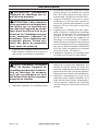
Figure 6 - 200,000 BTU Controls
Ignitor
Button
Control
Knob
Safety
Valve
TO STOP HEATER
1. Securely close valve on the propane
cylinder.
2. Continue to operate heater until all fuel in
the hose has burned.
3. Shut off main burner. Do this by turning
control knob to the OFF position. Make
sure you turn the knob until it stops.
TO RESTART HEATER
1. Securely close valve at propane cylinder.
2. Wait 5 minutes.
3. Restart following steps under To Start
Heater, page 6.
200,000 BTU MODEL
TO START HEATER
1. Open propane supply valve on propane
tank(s) slowly. NOTE: If not opened slow-
ly, excess-ow check valve on propane
tank may stop gas ow. If this happens,
you may hear a click inside the regulator
assembly, this is the check valve closing.
To reset the excess-ow check valve,
close propane supply valve and open
again slowly.
WARNING: BEFORE LIGHT-
ING PILOT, turn control knob
clockwise to the OFF position.
2. Press the red button on the safety valve
admitting gas to the pilot. Push and
release the ignition button until the pilot
lights. Hold valve button down for a max-
imum of 30 seconds while attempting
ignition. If heater does not ignite, release
control knob and wait 3 minutes before
attempting reignition. Note: Keep hands
and face away from outlet (around top of
shell) of heater while attempting to start
heater.
3. When pilot remains lit, set heater at the
desired heat level by turning control knob
counterclockwise. If burner goes out, turn
off gas. Turn control knob fully clockwise
to the OFF position. Check fuel supply. If
adequate fuel is available, restart heater
beginning at step #1.
TO STOP HEATER
1. Tightly close propane supply valve on
propane tank(s). Allow heater to burn
remaining fuel in hose.
2. Shut off main burner. Do this by turning
control knob fully clockwise to the OFF
position. Make sure you turn the knob
until it stops.
TO RESTART HEATER
1. Wait ve minutes after stopping heater.
2. Restart heater by following steps under
To Start Heater.

www.usaprocom.com
160311-01B8
TECHNICAL SERVICES
You may have further questions about installation, operation, or troubleshooting. If so, contact
ProCom Heating, Inc. at 1-866-573-0674.
When calling, please have your model and serial numbers of your heater ready.
ACCESSORIES
Purchase heater accessories and parts from your nearest dealer or service center. If they can
not supply an accessory or part, call ProCom Heating, Inc. at 1-866-573-0674.
CAUTION: Disconnect heater
from propane supply tank(s).
CAUTION: Be careful not to
locate ngers in groves on side
of heater, in vent holes or on
bottom of shell when collaps-
ing shell to the down position.
Severe cuts may occur. Always
wear hand protection when
grasping bare metal.
1. The heater should be inspected before
each use and at least annually by a qual-
ied person.
STORAGE
2. Before each use, check the soft "O" ring
seat at the bullnose of the POL tting. If
the "O" ring is cut, scuffed or otherwise
damaged, replace the POL tting.
3. When heater is not in use, the gas shall
be turned off at the propane/LP gas supply
cylinder(s) by closing the valve on the
cylinder.
4. Heater is to be stored indoors. The con-
nection between propane/LP gas supply
cylinder(s) and heater must be disconnect-
ed, cylinder(s) removed from the heater
and stored outdoors in accordance with
Chapter 5 of the Standard for Storage and
Handling of Liqueed Petroleum Gases
ANSI/NFPA 58 and CSA B149.1, Natural
Gas and Propane Installation Code.
5. Store in a dry, clean and safe place.
MAINTENANCE
WARNING: Never attempt
to service heater while it is
connected to propane supply,
operating or hot. Severe burns
can occur.
1. Keep heater clean.
2. Inspect heater before each use. Check
connections for leaks. Apply mixture of
liquid soap and water to connections.
Bubbles forming show a leak that must
be corrected. Correct all leaks at once.
3. Inspect hose/regulator assembly before
each use. If hose is highly worn or cut,
replace.
4. Have heater inspected yearly by a quali-
ed service person.

www.usaprocom.com
9160311-01B
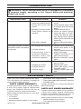
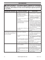
TROUBLESHOOTING
OBSERVED FAULT POSSIBLE CAUSE REMEDY
Burner fails to light. 1. Propane supply valve
closed on propane tank(s).
2. Excess flow check valve
closed.
3. Blockage in burner orice.
4. Piezo ignition system not
sparking.
5. Pilot orice clogged.
1. Open propane supply valve
slowly.
2.
Close propane supply valve
on propane tank and reopen
slowly.
3. Replace burner orice.
4. Check to assure ignitor
electrode gap is 0.195"
Check wire lead for dam-
age. Replace piezo ignitor
and/or ignitor electrode as
necessary.
5.
Clean or replace pilot assem-
bly.
Pilot lights but goes out when
automatic control valve button
is released.
1. Not enough warm up time.
2. Low gas pressure.
3. Thermocouple loose or
needs to be replaced.
4. Automatic control valve
needs to be replaced.
1. Relight, hold automatic
control valve button in 45
seconds.
2. Check propane tank(s) for
proper gas supply.
3. Tighten connection or re-
place thermocouple.
4. Replace automatic control
valve.
Burn rate is low. 1. Control valve is on LOW.
2. Plugged gas orice.
3. Low gas pressure.
4. Low fuel supply.
1. Turn valve counter clock-
wise to HIGH.
2. Replace gas orice.
3. Check gas supply; check
regulator output.
4. Consult propane gas sup-
plier.
WARNING: Never service heater while it is plugged in, connected
to propane supply, operating or hot. Severe burns and electrical
shock can occur.
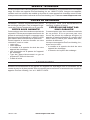
REPLACEMENT PARTS
Note: Use only original replacement parts.
This will protect your warranty coverage for
parts replaced under warranty.
PARTS UNDER WARRANTY
Contact authorized dealers of this product.
If they can’t supply original replacement
parts, call Customer Service toll free at
1-866-573-0674 for referral information.
When calling Customer Service or your deal-
er, have ready:
• Your name
• Your address
• Model and serial number of your heater
• How heater was malfunctioning
• Type of gas supply and Propane/LP tank size
• Purchase date
Usually, we will ask you to return the defective
part to the factory
PARTS NOT UNDER WARRANTY
Contact authorized dealers of this product.
If they can’t supply original replacement
part(s) call Customer Service toll free at
1-866-573-0674 for referral information.
When calling Customer Service have ready:
• Model number of your heater
• The replacement part number

www.usaprocom.com
160311-01B10
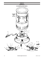
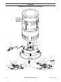
PARTS
MODELS
PCC80V & PCC200V
1
14
6
7
8
9
5
13
11
12
10
PCC80V
PCC80V
Upper
Shell
Shown
PCC200V
4
3
2
6
7
9
5
15
19
16
11
12
10
17
18

www.usaprocom.com
11160311-01B
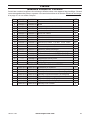
PARTS
MODELS
PCC80V & PCC200V
This list contains replaceable parts used in your heater. When ordering parts, follow the
instructions listed under Replacement Parts on page 9 of this manual.
ITEM PCC80V PCC200V DESCRIPTION QTY.
1 160257-01 160290-01 Electrode 1
2 160263-01 160263-02 Nozzle 1
3 160253-01 160286-01 Heat Shield 1
4 160270-01 160270-01 Brass Nozzle Adapter 1
5 160266-01 160293-01 Control Valve 1
6 160265-01 160265-01 Valve Nut 1
7 160256-01 160304-03 Knob 1
8 160267-01 ------ Brass Cap 1
9 160528-02 160528-01 Sleeve Cap 1
10 160269-01 160269-01 Brass Elbow, 1/4" NPT x 5/8" Flare 3/2
11 160292-01 160292-01 Thermocouple Nut 2
12 160261-01 160261-01 Thermocouple 1
13 160255-01 160255-01 Piezo Ignitor 1
14 160275-01 160284-01 Hose/Regulator Assembly 1
15 ------ 160296-01 Brass Elbow, 1/8" NPT x 7/16" Flare 2
16 ------ 160295-01 Brass Elbow, 1/4" NPT x 7/16" Flare 1
17 ------ 160298-01 Pilot Barrel Assembly 1
18 ------ 160297-01 Pilot Orice 1
19 ------ 160294-05 On/Off Valve 1
PARTS AVAILABLE - NOT SHOWN
160274-01 160274-01 Hardware Package 1
160313-01 160316-02 Operation Decal (English) 1
160315-01 160315-02 Operation Decal (Spanish) 1
160315-03 160315-04 Operation Decal (French) 1
160312-01 160312-04 Hang Tag (English) 1
160312-02 160312-05 Hang Tag (Spanish) 1
160312-03 160312-06 Hang Tag (French) 1
160316-01 160316-02 Model Decal 1

160311-01
Rev. B
11/14
REGISTER YOUR PRODUCT AT WWW.USAPROCOM.COM
IMPORTANT: We urge you to register your product within 10 days of date of installation, complete
with entire serial number which can be found on the rating plate. Please ll out the warranty infor-
mation above for your personal records. Retain this manual for future reference.
Always specify model and serial numbers when communicating with customer service.
We reserve the right to amend these specications at any time without notice. The only warranty applicable
is our standard written warranty. We make no other warranty, expressed or implied.
LIMITED WARRANTY
ProCom Heating, Inc. warrants this product to be free from defects in materials and components for ONE
(1) year from the date of rst purchase, provided that the product has been properly installed by a qualied
installer in accordance with all local codes and instructions furnished with the unit, operated and main-
tained in accordance with all applicable instructions. To make a claim under this warranty, the Bill of Sale
or cancelled check must be presented.
RESPONSIBILITY OF OWNER
This warranty is extended only to the original retail purchaser. This warranty covers the cost of part(s)
required to restore this heater to proper operating condition. Warranty part(s) MUST be obtained through
ProCom Heating, Inc. who will provide original factory replacement parts. Failure to use original factory
replacement parts voids this warranty. The heater MUST be installed by a qualied installer in accordance
with all local codes and instructions furnished with the unit.
WHAT IS NOT COVERED
This warranty does not apply to parts that are not in original condition because of normal wear and tear or
parts that fail or become damaged as a result of misuse, accidents, lack of proper maintenance or defects
caused by improper installation. Travel, diagnostic cost, labor, transportation and any and all such other
costs related to repairing a defective heater will be the responsibility of the owner.
TO THE FULL EXTENT ALLOWED BY THE LAW OF THE JURISDICTION THAT GOVERNS THE SALE
OF THE PRODUCT, THIS EXPRESS WARRANTY EXCLUDES ANY AND ALL OTHER EXPRESSED
WARRANTIES AND LIMITS THE DURATION OF ANY AND ALL IMPLIED WARRANTIES. INCLUDING
WARRANTIES OF MERCHANTABILITY AND FITNESS FOR A PARTICULAR PURPOSE TO ONE (1)
YEAR ON ALL COMPONENTS FROM THE DATE OF FIRST PURCHASE. PROCOM HEATING, INC.'S
LIABILITY IS HEREBY LIMITED TO THE PURCHASE PRICE OF THE PRODUCT AND PROCOM HEAT-
ING, INC. SHALL NOT BE LIABLE FOR ANY OTHER DAMAGES WHATSOEVER INCLUDING INDIRECT.
INCIDENTAL OR CONSEQUENTIAL DAMAGES.
Some states do not allow a limitation on how long an implied warranty lasts or an exclusion or limitation of
accidental or consequential damages, the above limitation on implied warranties, or exclusion or limitation
on damages may not apply to you.
This warranty gives you specic legal right, and you may also have other rights that vary from state to state.
WARRANTY
KEEP THIS WARRANTY
Model _______________________________
Serial No. ____________________________
Date Purchased _______________________
Keep receipt for warranty verication.
ProCom Heating, Inc.
Bowling Green, KY 42101
www.usaprocom.com
1-866-573-0674

¿Preguntas, problemas, piezas faltantes? Antes de volver a la tienda, llame a
nuestro Departamento de Servicio al Cliente al 1-866-573-0674, de lunes a viernes de
7:30 a.m. a 4:15 p.m., Hora del Centro, o envíe un correo electrónico a
customerservice@usaprocom.com.
CALENTADOR DE
CONVECCIÓN PARA
CONSTRUCCIÓN DE
PROPANO MANUAL DEL
PROPIETARIO
VARIABLE 40-80.000 BTU/H
75-200.000 BTU/H
MODELOS
PCC80V, PCC200V
IMPORTANTE: Lea y comprenda este manual antes de
ensamblar, encender o dar servicio al calentador. El
uso inadecuado del calentador puede causar lesiones
graves. Conserve este manual para referencias futuras.
ADVERTENCIA GENERAL DE PELIGRO:
No cumplir con las precauciones e instrucciones propor-
cionadas con este calentador puede causar la muerte,
lesiones físicas graves y pérdidas o daños a la propiedad
debido al peligro de incendio, explosión, quemaduras,
asxia, intoxicación con monóxido de carbono y/o cho-
ques eléctricos.
Únicamente las personas que puedan entender y seguir las
instrucciones deberán usar o dar servicio a este calentador.
Si necesita ayuda o información sobre el calentador,
como manuales de instrucciones, etiquetas, etc., comu-
níquese con el fabricante.

www.usaprocom.com
160311-01B14
ADVERTENCIA: No usar
en residencias ni en vehículos
recreativos.
El calentador está diseñado para utilizarse como
calentador para construcción de acuerdo con el
estándar ANSI Z83.7•CGA2.2.14. Otras normas
rigen el uso de gases combustibles y productos
de calefacción para usos especícos. La auto-
ridad local puede informarle acerca de éstas.
El propósito principal de los calentadores para
construcción es proporcionar calefacción tem-
poral a edicios en construcción, modicación
o reparación. Cuando se usa correctamente, el
calentador proporciona calefacción económica
y segura. Los productos de combustión se ven-
tilan al área que se está calentando.
No podemos prever todos los usos que se les
pueden dar a nuestros calentadores. CONSUL-
TE A LA AUTORIDAD LOCAL DE SEGURIDAD
CONTRA INCENDIOS SI TIENE PREGUNTAS
ACERCA DEL USO DE CALENTADORES.
Otras normas rigen el uso de gases combusti-
bles y productos que producen calor para usos
especícos. Las autoridades locales pueden
informarle sobre estos.
SEGURIDAD
ADVERTENCIA: Este produc-
to contiene y/o genera químicos
que el Estado de California reco-
noce que causan cáncer, defectos
de nacimiento u otros daños re-
lacionados con la reproducción.
ADVERTENCIA: Peligro de
incendio, quemaduras, inhala-
ción y explosión. Mantenga los
combustibles sólidos, como ma-
teriales de construcción, papel o
cartón a una distancia segura del
calentador según se recomienda
en las instrucciones. Nunca use
el calentador en espacios que
contengan o podrían contener
combustibles volátiles o trans-
portados por aire o productos
como gasolina, solventes, dilu-
yente de pintura, partículas de
polvo o químicos desconocidos.
TABLA DE CONTENIDOS
Especicaciones ...................................... 14
Seguridad ................................................ 14
Desempaque ........................................... 16
Teoría del funcionamiento ....................... 16
Identicación del producto ....................... 16
Ventilación .............................................. 17
Suministro de propano ............................ 17
Instalación ............................................... 17
Funcionamiento ....................................... 19
Almacenamiento ...................................... 21
Mantenimiento ......................................... 21
Servicio técnico ....................................... 21
Accesorios ............................................... 21
Solución de problemas ............................ 22
Piezas de repuesto .................................. 23
Piezas ...................................................... 24
Garantía................................................... 26
ESPECIFICACIONES
80,000 Btu 200,000 Btu
Tipo de gas Sólo propano o gas LP
Clasicación 40,000 - 80,000 Btu/h
(11.7 - 23.4 kW)
75,000 - 200,000 Btu/h
(22.0 - 58.6 kW)
Presión del suministro de gas al regulador Máx - presión del tanque
Mín: 1 psig (6.89 kPa) Mín: 15 psig (103 kPa)
Presión de salida del regulador de pre-
sión del suministro de gas
22" (55.9 cm) de c.a. 10 psig (68.9 kPa)
Encendido
Encendedor piezoeléctrico
Clasicación de temperatura ambiente mínima
0° F (-17.8° C) 0° F (-17.8° C)
Consumo de combustible
1.85 - 3.7 lb/hr
(0.84 – 1.63 kg/hr)
3.5 - 9.2 lb/hr
(1.57 - 4.2 kg/hr)
Número del puerto del oricio de combustible
6 6
Tamaño del puerto del oricio de combustible
0.041" (1.04 mm) 0.032" (0.81 mm)

www.usaprocom.com
15160311-01B
PELIGRO: ¡La intoxicación
con monóxido de carbono puede
resultar en la muerte!
Intoxicación con monóxido de carbono:
algunas personas sufren mayores efectos del
monóxido de carbono que otras. Los prime-
ros signos de intoxicación con monóxido de
carbono se asemejan a los de la gripe, con
dolor de cabeza, mareo y/o náusea. Si usted
presenta estos síntomas, es posible que el
calentador no esté funcionando correctamen-
te. ¡Respire aire fresco inmediatamente!
Compruebe que haya ventilación adecuada
y haga que reparen el calentador.
Gas propano: el gas propano es inodoro. Al gas
propano se le agrega un agente oloroso. El olor
le ayuda a detectar las fugas de gas propano. Sin
embargo, el olor que se añade al gas propano
puede desvanecerse. Es posible que haya gas
propano presente aunque no haya ningún olor.
Asegúrese de leer y comprender todas las
advertencias. Conserve este manual para re-
ferencia. Es su guía para la operación segura
y correcta de este calentador.
Para uso con gas propano so-
lamente
1. Instale y use el calentador cuidadosamente.
Siga las ordenanzas y los códigos locales.
A falta de ordenanzas y códigos locales,
consulte la Norma de almacenamiento y
manejo de gas licuado de petróleo, ANSI/
NFPA 58 y el Código de instalación de gas
natural y propano, CAN/CGA B149.1. Ésta
proporciona instrucciones acerca del alma-
cenamiento y manejo seguro del propano.
2. Este producto ha sido aprobado para su
uso en el Estado de Massachusetts.
3. Use solamente el montaje de gas propano
para la extracción de vapores.
4.
Proporcione una ventilación adecuada.
Antes de usar el calentador, deje una aber-
tura mínima de 2,5 pies
2
(0,23 metros
2
)
(calentadores 80.000 BTU) o 6,0 pies
2
(0,56
metros
2
) (calentadores 200.000 BTU) para
permitir la entrada de aire fresco del exterior.
5. Para uso en interiores solamente. Se
debe proporcionar la ventilación adecua-
da. No use el calentador en exteriores.
6. Mantenga el calentador alejado de co-
rrientes fuertes de aire, viento, rocío, lluvia
o goteos de agua.
7. No use el calentador en viviendas ocupa-
das ni en dormitorios o alojamientos.
8. No use el calentador en un sótano ni
debajo del nivel del suelo. El gas propano
es más pesado que el aire. Si se produce
una fuga, el gas propano se puede asen-
tar en el nivel más bajo posible.
9. Mantenga el área cerca del aparato des-
pejada y libre de materiales combustibles,
gasolina, diluyentes para pintura y otros
vapores y líquidos inamables. El polvo
es combustible. No use el calentador en
áreas con un contenido alto de polvo.
10. Distancias mínimas de los combustibles:
Calentadores 80.000 BTU
Laterales: 3 pies (91 cm); Parte supe-
rior: 6 pies (1,83 m)
Calentadores 200.000 BTU
Laterales: 3 pies (91 cm); Parte supe-
rior: 7 pies (2,1 m)
Sitúe el aparato a 3 m (10 pies) de lonas,
toldos o cubiertas similares y asegure
éstas para evitar que se sacudan o se
muevan con la acción del viento.
11. Mantenga el calentador por lo menos
1,8 m (6 pies) del tanque de propano(s)
en EE.UU. o 3 m (10 pies) del tanque de
propano(s) en Canadá. No apunte el calen-
tador hacia el (los) tanque(s) de propano
dentro de un área de 6 m (20 pies).
12. Mantenga los tanques de propano por
debajo de los 37,8º C (100° F).
13. Use sólo la manguera y el regulador
preinstalado en la fábrica que se incluyen
con el calentador.
14. Antes de cada uso, verique si el calen-
tador ha sufrido algún daño. No use un
calentador dañado.
15. Revise la manguera antes de cada uso
del calentador. Si la manguera está muy
desgastada o con roturas, remplácela
con una manguera especicada por el
fabricante antes de usar el calentador.
16. No altere el calentador. Mantenga el
calentador en su estado original.
17.
No use el calentador si éste ha sido alterado.
18. Sitúe el calentador sobre una supercie
estable y nivelada. No mover mientras el
calentador está caliente o en funciona-
miento. Posición el calentador correcta-
mente antes de usar.
19. No está diseñado para su uso en pisos
terminados.
SEGURIDAD

www.usaprocom.com
160311-01B16
20. Nunca bloquee la entrada de aire (parte
inferior de la cubierta) o la salida de aire
(alrededor de la parte superior de la cu-
bierta) del calentador.
21. No deje el calentador desatendido.
22. Evite que los niños y los animales se
acerquen al calentador.
23. Nunca mueva, maneje o dé servicio a un
calentador caliente o en funcionamiento.
Pueden producirse quemaduras graves.
Debe esperar 15 minutos después de
apagar el calentador.
SEGURIDAD
24. Para evitar lesiones, use guantes cuando
manipule el calentador.
25. Nunca je tubería al calentador.
26. Cierre el suministro de gas propano al
calentador cuando no se esté usando.
27. Use sólo piezas de repuesto originales.
Este calentador debe usar piezas diseña-
das especícamente. No las sustituya ni
use piezas genéricas. El uso de piezas de
repuesto inadecuadas puede ocasionar
lesiones graves o fatales.
28. No dirija el calor hacia los cilindros de gas
propano/LP a menos de 20 pies (6 m).
DESEMPAQUE
1. Retire todos los elementos de empaque
aplicados al calentador para su envío.
Mantenga los tapones de plástico (jados
al ensamblaje de manguera-regulador y
al conector de entrada) puestos cuando
se guarde.
2. Saque todos los elementos de la caja.
3. Revise todos los elementos para ver si
hay daños debidos al transporte. Si el
calentador está dañado, informe de in-
mediato al distribuidor a quien lo compró.
TEORÍA DEL FUNCIONAMIENTO
El sistema de combustible: el ensamblaje de manguera-regulador se ja al suministro de
gas propano. Esto proporciona combustible al calentador.
El sistema de encendido: el encendedor piezoeléctrico enciende el piloto.
El sistema de control automático: este sistema ocasiona que el calentador se apague si
se extingue la llama.
IDENTIFICACIÓN DEL PRODUCTO
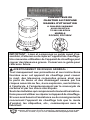
Figura 1 - Se muestra el modelo de 80.000 BTU/h
Cubierta exterior
Encendedor
Botón de la perilla de control
de la válvula de bola

www.usaprocom.com
17160311-01B
VENTILACIÓN
ADVERTENCIA: Procure tener al menos una abertura de aire fres-
co del exterior de 2,5 pies
2
(0,23 metros
2
) mientras el calentador está
encendido. Si no se procura ventilación de aire fresco del exterior,
puede haber una intoxicación con monóxido de carbono. Procure una
abertura de aire fresco del exterior antes de encender el calentador.
SUMINISTRO DE PROPANO
Usted debe proveer el gas propano y el (los)
tanque(s) de gas propano.
Use el calentador solamente con un sistema
de suministro con extracción de vapores de
propano. Consulte el capítulo 5 de la Norma
de almacenamiento y manejo de gas licuado
de petróleo, ANSI/NFPA 58 y/o la norma CAN/
CGA B149.2. La biblioteca local o el departa-
mento de bomberos debe tener este folleto.
Este calentador funciona con un tanque de
propano de 20 libras (9,07 kg). Sin embargo,
sólo puede hacer funcionar el calentador en
la posición BAJA cuando hace frío leve. En
lugares con más calefacción o cuando el
tiempo está más frío, deberá usar tanques
más grandes.
La cantidad de gas propano lista para usarse
de los tanques de propano varía. Dos factores
determinan esta cantidad:
1. La cantidad de gas propano en el (los)
tanque(s)
2. La temperatura del (de los) tanque(s)
El cuadro a continuación muestra los tanques
mínimos de 100 libras (45 kg) necesarios para
hacer funcionar el calentador. Conecte los
tanques entre sí con un tubo múltiple.
Temperatura promedio °C
(°F) en la ubicación de los
tanques
Número de
tanques
Modelos 80.000 BTU
-6.7 (20°) a 15,6° (60°) 1
-17,8° (0°) a -6,7° (20°) 2
Modelos 200.000 BTU
-6,7° (20°) a 15,6° (60°) 2
-17,8° (0°) a -6,7° (20°) 3
A temperaturas más bajas se vaporiza menos
gas. El surtidor de gas de su localidad le ayu-
dará a seleccionar el sistema de suministro
apropiado.
INSTALACIÓN
ADVERTENCIA: Revise y
comprenda las advertencias en
la sección Seguridad, página
14. Son necesarias para hacer
funcionar este calentador de
manera segura. Siga todas los
códigos locales al utilizar este
calentador.
PRECAUCIÓN: Nunca en-
cienda y/o haga funcionar el ca-
lentador salvo que las cubiertas
estén totalmente extendidas y
aseguradas en su posición.
CUBIERTA EXTERIOR
IMPORTANTE: Cuando retire el calentador
por primera vez de la caja, la cubierta exterior
está en posición hacia abajo. Protéjase las
manos antes de levantar la cubierta exterior.
Nunca tome metal expuesto sin usar protec-
ción para las manos.
1. Debe proteger sus manos mientras rea-
liza este paso. Levante carcasa exterior
hacia arriba como se muestra en la Figura
2, en la página 18, hasta que los oricios
de tornillo de línea hacia arriba y agujeros
ranurados son visibles.

www.usaprocom.com
160311-01B18
2. Instalar 3 tornillos en los oricios inferio-
res, como se muestra en la Figura 2. Deje
reposar la cubierta superior en los tornillos
inferiores. Agujeros y ranuras se alinean.
3. Instale 3 tornillos en los agujeros supe-
riores para asegurar la cubierta superior.
El aparato no debe ser utilizado a menos
que la capa exterior se extiende correc-
tamente y completamente asegurado en
su lugar.
Figura 2 - Cómo levantar la cubierta exterior
Tornillo,
Instalar
Última
Tornillo,
Instalación
de la
primera
Cubierta
exterior
INSTALACIÓN
CONEXIÓN A LA
ALIMENTACIÓN DE GAS
ADVERTENCIA: Pruebe to-
das las tuberías de gas y sus
conexiones para saber si hay
fugas después de instalar o dar
servicio. Nunca use una llama al
descubierto para vericar una
fuga. Aplique una mezcla de ja-
bón líquido y agua en todas las
uniones. La formación de bur-
bujas indicará una fuga. Repare
todas las fugas inmediatamente.
1. Proporcione un sistema de alimentación
de propano (vea Suministro de propano,
página 17).
2. Conecte el niple de gas combustible
del ensamblaje de manguera-regulador
a el (los) tanque(s) de propano. Gire el
niple de gas combustible en el sentido
contrario al de las manecillas del reloj en
las roscas del tanque. Apriete rmemente
usando una llave. IMPORTANTE: apriete
el regulador con la ventila apuntando ha-
cia abajo. Apuntar la ventila hacia abajo
protege el regulador del daño climático.
3. Conecte la manguera a la entrada de la
válvula. Apriete rmemente usando una
llave. Debe usar el regulador suministrado
con el calentador aunque el tanque de
propano ya tenga uno.
4. Abra lentamente la válvula del suministro
de propano en el (los) tanque(s) de pro-
pano. Nota: si no se abre lentamente, la
válvula de exceso de ujo del tanque de
propano puede detener el ujo del gas.
Si esto sucede, es posible que escuche
un chasquido al cerrarse la válvula de ex-
ceso de ujo. Para restablecer la válvula
de exceso de ujo, cierre la válvula del
suministro de propano y ábrala de nuevo
lentamente.
5. Revise todas las conexiones en busca
de fugas. Aplique una mezcla de jabón
líquido y agua a todas las uniones de la
línea de gas. La formación de burbujas
indica una fuga que se debe corregir.
Figura 3 - Posición del regulador
Figura 4 - Manguera y entrada de la válvula
Tanque de
propano
Válvula del
suministro de
propano
Regulador
Manguera
Niple de rosca
invertida
Manguera
Entrada de
la válvula

www.usaprocom.com
19160311-01B
FUNCIONAMIENTO
ADVERTENCIA: Revise y
comprenda las advertencias en
la sección Seguridad, página
14. Son necesarias para hacer
funcionar este calentador de
manera segura. Siga todas los
códigos locales al utilizar este
calentador.
80.000 BTU MODELO
PARA ENCENDER EL
CALENTADOR
1. Asegúrese de que la unidad esté apa-
gada oprimiendo ligeramente y girando
la perilla de control completamente en
el sentido de las manecillas del reloj a la
posición de APAGADO. Abra lentamente
la válvula del suministro de propano en
el(los) tanque(s) de propano.
2. Empuje y gire la perilla de control en
sentido contrario al de las manecillas del
reloj a la posición de BAJA. Con la perilla
de control oprimida, presione y suelte el
botón del ignitor piezo. Continúe presio-
nando el botón del ignitor piezo hasta
que se encienda el quemador. Mantenga
presionada la perilla durante un máximo
de 15 segundos mientras se intenta la
ignición. Si el calentador no arde, suelte
la perilla de control y espere 5 minutos
antes de volver a intentar la ignición.
3. Después de la ignición, mantenga pre-
sionada la perilla de control durante 30
segundos aproximadamente. Esto activa
el sistema de control automático.
4. Cuando el quemador principal permanez-
ca encendido, coloque el calentador en el
nivel de calor deseado oprimiendo ligera-
mente la perilla de control y girándola en
sentido contrario al de las manecillas del
reloj a las posiciones de Media o Alta.
Figura 5 - 80.000 BTU Controls
Encendedor
Perilla de control
5. Si se apaga el quemador, cierre el gas.
Presione ligeramente y gire la perilla
de control completamente en el sentido
de las manecillas del reloj a la posición
de APAGADO. Revise el suministro de
combustible. Si el combustible adecuado
está disponible, vuelva a encender el
calentador, comenzando en el paso 1.
PARA APAGAR EL
CALENTADOR
1. Cierre rmemente la válvula del cilindro
de propano.
2. Continúe haciendo funcionar el calenta-
dor hasta que todo el combustible de la
manguera se haya quemado.
3. Apague el quemador principal. Hágalo
girando la perilla de control a la posición
de APAGADO. Asegúrese de girar la
perilla hasta que se detenga.
PARA VOLVER A ENCENDER EL
CALENTADOR
1. Cierre rmemente la válvula del cilindro
de propano.
2. Espere 5 minutos.
3. Vuelva a encender siguiendo el procedi-
miento Para encender el calentador.

www.usaprocom.com
160311-01B20
FUNCIONAMIENTO
200.000 BTU MODELO
PARA ENCENDER EL
CALENTADOR
1. Abra lentamente la válvula del suministro
de propano en el (los) tanque(s) de pro-
pano. Nota: Si no se abre lentamente,
es posible que la válvula de exceso de
ujo del tanque de propano detenga el
ujo del gas. Si esto sucede, es posible
que escuche un chasquido dentro del
ensamblaje del regulador al cerrarse la
válvula de exceso de ujo. Para restable-
cer la válvula de exceso de ujo, cierre la
válvula del suministro de propano y ábrala
de nuevo lentamente.
ADVERTENCIA: ANTESDE
ENCENDER EL PILOTO, Gire
la perilla de control en sentido
horario hasta la posición OFF.
2. Presione el botón rojo de la válvula del
piloto de seguridad dejando asi que el gas
pase al piloto. Presione y suelte el botón
de encendido hasta que se encienda el
piloto. Mantenga presionada la botón
de la válvula durante un máximo de 30
segundos mientras se intenta la ignición.
Si el calentador no arde, suelte la perilla
de control y espere 3 minutos antes de
volver a intentar la ignición. Nota: Man-
tenga las manos y la cara alejados de la
salida (alrededor de la parte superior de la
cubierta) del calentador mientras intenta
encenderlo.
3. Cuando el piloto permanece encendido,
coloque el calentador en el nivel de calor
deseado girando la válvula de control en
sentido contrario al de las manecillas del
reloj. Si se apaga el quemador, cierre el
gas. Gire la perilla de control completa-
mente en el sentido de las manecillas
del reloj a la posición OFF. Revise el
suministro de combustible. Si el combus-
tible adecuado está disponible, vuelva a
encender el calentador comenzando en
el paso 1.
PARA APAGAR EL
CALENTADOR
1. Cierre rmemente la válvula del suminis-
tro de propano en el(los) tanque(s) de
propano. Deje que el calentador queme el
combustible que queda en la manguera.
2. Cierre la válvula del quemador principal.
Hágalo girando la perilla de control com-
pletamente en el sentido de las manecillas
del reloj a la posición OFF. Asegúrese de
girar la perilla hasta que se detenga.
PARA VOLVER A ENCENDER EL
CALENTADOR
1. Espere cinco minutos después de detener
el calentador.
2. Vuelva a encender el calentador siguien-
do los pasos que se indican en Para
iniciar el calentador.
Encendedor
Perilla de
control
Figura 6 - 200.000 BTU Controls
Válvula de
seguridad
La page est en cours de chargement...
La page est en cours de chargement...
La page est en cours de chargement...
La page est en cours de chargement...
La page est en cours de chargement...
La page est en cours de chargement...
La page est en cours de chargement...
La page est en cours de chargement...
La page est en cours de chargement...
La page est en cours de chargement...
La page est en cours de chargement...
La page est en cours de chargement...
La page est en cours de chargement...
La page est en cours de chargement...
La page est en cours de chargement...
La page est en cours de chargement...
La page est en cours de chargement...
La page est en cours de chargement...
La page est en cours de chargement...
La page est en cours de chargement...
-
 1
1
-
 2
2
-
 3
3
-
 4
4
-
 5
5
-
 6
6
-
 7
7
-
 8
8
-
 9
9
-
 10
10
-
 11
11
-
 12
12
-
 13
13
-
 14
14
-
 15
15
-
 16
16
-
 17
17
-
 18
18
-
 19
19
-
 20
20
-
 21
21
-
 22
22
-
 23
23
-
 24
24
-
 25
25
-
 26
26
-
 27
27
-
 28
28
-
 29
29
-
 30
30
-
 31
31
-
 32
32
-
 33
33
-
 34
34
-
 35
35
-
 36
36
-
 37
37
-
 38
38
-
 39
39
-
 40
40


ProCom Heating 200068 Manuel utilisateur
- Taper
- Manuel utilisateur
dans d''autres langues
- English: ProCom Heating 200068 User manual
- español: ProCom Heating 200068 Manual de usuario