Thermador PRD366GHC/10 Guide d'installation
- Catégorie
- Cuisinières
- Taper
- Guide d'installation
Ce manuel convient également à

INSTALLATION MANUAL
For THERMADOR Professional
PRO HARMONY ® Dual Fuel Ranges
MANUEL D'INSTALLATION
Pour toutes les cuisinieres mixtes
THERMADOR Professional McPRO HARMONY Mc
MANUAL DE INSTALACION
Para Estufas de Todo Tipo de Gas THERMADOR
Professional PRO HARMONY ®
Ther ador
REAL INNOVATIONS FOR REAL COOKS TM
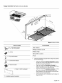
Models/
Modeles/
Modelos:
PRD30
PRD36
PRD48

Table of Contents
Safety Instructions .......................................... 1
Important Installation Information ............................. 2
Ste _ 1: Ventilation Requirements ........................................ 3
Ste _ 2: Cabinet Preparation ............................................ 4
Ste _ 3: Unpacking, Moving and Placing the Range .......................... 9
Ste 34: Installing Anti-Tip Device ....................................... 11
Ste 3 5: Gas Requirements and Hookup .................................. 13
Ste3 6: Electrical Requirements, Connection & Grounding ................... 14
Ste _ 7: Backguard Installation (optional) ................................... 17
Ste 3 8: Door Removal and Reinstallation ................................. 22
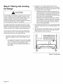
Ste 3 9: Placing and Leveling the Range .................................. 24
Ste 3 10: Burner Test and Adjustment .................................... 27
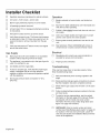
Installer Checklist .......................................... 28
To Clean and Protect Exterior Surfaces ........................ 29
This THERMADOR ® appliance is made
by BSH Home Appliances Corporation
1901 Main Street, Suite 600
Irvine, CA 92614
Questions?
1-800-735-4328
www.thermador.com
We look forward to hearing from you!

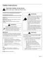
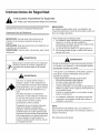
Safety Instructions
Important Safety Instructions
READ AND SAVE THESE INSTRUCTIONS
APPROVED FOR ALL RESIDENTIAL APPLIANCES
FOR RESIDENTIAL USE ONLY
IMPORTANT: Save these Instructions for the Local Gas
Inspector's use.
INSTALLER: Please leave these Installation Instructions
with this unit for the owner.
OWNER: Please retain these instructions for future
reference.
WARNING
ELECTRICAL SHOCK HAZARD--
Disconnect power before installing or servicing.
Before turning power ON, be sure that all
controls are in the OFF position. Failure to do
so can result in death or electrical shock.
IMPORTANT:
Local codes vary. Installer is responsible for ensuring that
the installation, gas connections, and grounding comply
with all applicable codes. Failure to follow appropriate local
codes and regulations may void the warranty.
For
1.
,
3.
Massachusetts Installations:
Installation must be performed by a qualified or
licensed contractor, plumber or gas fitter qualified or
licensed by the state, province or region where this
appliance is being installed.
Shut-off valve must be a "T" handle gas cock.
Flexible gas connector must not be longer than 36"
(914mm).
Note:
This Range is NOT designed for installation in
manufactured (mobile) homes or Recreational Park
Trailers.
DO NOT install this range outdoors.
WARNING:
A child or adult can tip the range over and
be killed or seriously injured. Verify that the
anti-tip bracket is securely installed.
Ensure the anti-tip bracket is engaged
when the range is moved.
Do not operate the range without the anti-
tip bracket in place. Failure to follow the
instructions in this manual can result in
death or serious burns to children and
adults.
Check for proper installation and use of
anti-tip bracket. Carefully tip range forward
pulling from the back to ensure that the
anti-tip bracket engages the range leg and
prevents tip-over. Range should not move
more than 1 inch (2.5cm).
WARNING:
If the information in this manual is not followed exactly, a
fire or explosion may result causing property damage,
personal injury or death.
-- Do not storeor use gasoline or other flammable vapors
and liquids in the vicinity of this or any other appliance.
WHAT TO DO IFYOU SMELLGAS
• Do not try to light any appliance.
• Do not touch any electrical switch.
• Do not use any phone in your building.
• Immediately call your gas supplier from a
neighbor's phone. Follow the gas supplier's
instructions.
• If you cannot reach your gas supplier, call the
fire department.
Installationand service must be performed by a qualified
installer, service agency or the gas supplier.
English 1

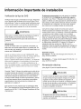
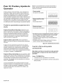
Important Installation Information
GAS type verification
Verify the type of gas supplied to the location. Ensure that
the appliance is connected to the type of gas for which it is
certified. All models are certified for use with natural gas.
Field conversion of the appliance for use with propane gas
supply will require a conversion kit (PALPKITHC).
Gas Supply:
Natural Gas -- 6 inch water column. (14.9 mb) min., 14
inch (34.9 mb) maximum
Propane Gas -- 11 inch water column. (27.4 mb) min., 14
inch (34.9 mb) maximum
Electric Power Supply:
(See page 14for specifications.)
Check local building codes for the proper method of
appliance installation. Local codes vary and it is the
responsibility of the installer to ensure installation is in
accordance with these codes. Installation, electrical
connections and grounding must comply with all applicable
codes. In the absence of local codes the appliance should
be installed in accordance with the National Fuel Gas Code
ANSI Z223. I/NFPA 54 current issue and National Electrical
Code ANSI/NFPA 70-current issue. In Canada, installation
must be in accordance with the CAN 1-B149.1 and .2 -
Installation Codes for Gas Burning Appliances and/or local
codes.
WARNING
To avoid possible burn or fire hazard, a backguard
designed specifically for this range must be installed
whenever the range is used.
IMPORTANT:
When installing against a combustible surface, a High Shelf
or Low Backguard is required. A THERMADOR ® High
Shelf or Low Backguard must be purchased separately.
See Step 7 for backguard, kits and installation information.
When using the Flush Island Trim, THERMADOR
recommends a minimum 12" (305 mm) rear clearance to a
combustible surface (see Figure 1, Cabinet Clearances).
Clearances from non-combustible materials are not part of
the ANSI Z21.1 scope and are not certified by
CSA. Clearances of less than 12" (305 mm) must be
approved by the local codes and/or by the local authority
having jurisdiction.
Refer to "Chart C: Backguard Kit Model Numbers" on
page 17, for the correct backguard models that are
designed for this range. After selecting the correct
backguard, the range must be installed properly, using the
minimum clearances to combustible surfaces specified in
the Cabinet Preparation instructions beginning on page 4.
Verify that the appliance is correct for the type of gas being
provided. Refer to "Step 5: Gas Requirements and
Hookup" on page 13 before proceeding with the
installation.
CAUTION
When connecting the unit to propane gas, make certain
the propane gas tank is equipped with its own high-
pressure regulator in addition to the pressure regulator
supplied with the range. The maximum gas pressure to
this appliance must not exceed 14.0" water column
(34.9 mb) from the propane gas tank to the pressure
regulator.
CAUTION
This unit is designed as a cooking appliance. Based on
safety considerations, never use itfor warming or
heating a room.
It is stronqlv recommended that this appliance be installed
in conjunction with a suitable overhead vent hood (see
"Step 1: Ventilation Requirements" on page 3). Due to the
high heat capability of this unit, particular attention should
be paid to the hood and duct work installation to assure it
meets local building codes.
English 2

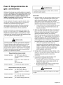
ThisappliancehasbeentestedinaccordancewithANSI
Z21.1,StandardforHouseholdCookingAppliances(USA)
andinaccordancewithCAN1.1-M81DomesticGas
Ranges(Canadian).
Thisappliancecomplieswithoneormoreofthefollowing
standards:
• UL858,StandardfortheSafetyofHouseholdElectric
Ranges
• UL923,StandardfortheSafetyofMicrowaveCooking
Appliances
• UL507,StandardfortheSafetyofElectricFans
• ANSIZ21.1,AmericanNationalStandardfor
HouseholdCookingGasAppliances
• CAN/CSA-C22.2No.113-M1984FansandVentilators
• CAN/CSA-C22.2No.61-M89HouseholdCooking
Ranges
Itistheresponsibilityoftheownerandtheinstallerto
determineifadditionalrequirementsand/orstandards
applytospecificinstallations.
2- 1/2"wrenches 1/8"(3.17mm)drillbit
3/16"(4.76mm)drillbit 12"Adjustablewrench
Handorelectricdrill Tapemeasure
T-20Torxscrewdriver Markinginstrument
Level Furnituredolly
Phillips&flathead Protectivegloves
screwdrivers
Items Not Included .......
3/16" (4.76mm) Drywall / Pipe Compound / Tape
Concrete Anchors
Rope/Twine 3/4" (19mm) Flex Line
Strain Relief Cord Kit or Conduit
2 - NPT Flare Adapters
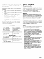
Step 1: Ventilation
Requirements
It is stronqlv recommended that a suitable exhaust hood be
installed above the range. Downdraft ventilation should not
be used. The table on page 4 indicates the ventilation hood
options and blower capacity guidelines that are
recommended for use with all THERMADOR ® ranges.
IMPORTANT:
Ventilation hoods and blowers are designed for use with
single wall ducting. However, some local building codes or
inspectors may require double wall ducting. Consult local
building codes and/or local agencies, before starting, to
assure that hood and duct installation will meet local
requirements.
Due to the high heat of the rangetop burners, do not install
a microwave oven/ventilator combination above the range,
as these type of units do not provide the proper ventilation
and are not suitable for use with the range.
NOTICE:
Most range hoods contain combustible components which
must be considered when planning the installation.
,
,
,
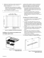
Select Hood and Blower Models:
For wall installations, the hood width must, at a
minimum, equal the width of the range. Where space
permits, a hood larger in width than the range/rangetop
may be desirable for improved ventilation performance.
For island installations, the hood width should
overhang the width of the range by a minimum of 3"
(76mm) on each side.
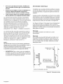
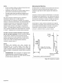
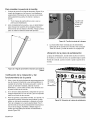
Hood Placement:
For best smoke elimination, the lower edge of the hood
should be installed 30" (762mm) above the range
cooking surface (see Figure 1).
If the hood contains any combustible materials (i.e. a
wood covering), it must be installed a minimum of 36"
(914mm) above the cooking surface (see Figure 1).
Consider Make-Up Air:
Due to the high volume of ventilation air, a source of
outside replacement air is recommended. This is
particularly important for tightly sealed and insulated
homes. A qualified heating and ventilating contractor
should be consulted.
English 3

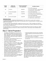
Range Range Top Cubic Feet per Minute
I ventilation uptlons
Width Configuration (min requirement)
30" or 36" Pro Wall Hood
30" 4 burners 800 CFM 30" or 36" Custom Insert w/optional blower
42" Island Hood w/optional blower
4 burners with griddle 800 CFM 36" or 42" Pro Wall Hood
36" 36" Custom Insert w/optional blower
6 burners 1100 CFM
42" or 48" Island Hood w/optional blower
48" or 54" Pro Wall Hood**
48" 6 burners with griddle 1200 CFM 48" Custom Insert w/optional blower
54" Island Hood w/optional blower
IMPORTANT NOTES:
It is recommended that a THERMADOR PROFESSIONAL ® wall or island hood or custom insert is used with
THERMADOR PROFESSIONAL ranges. Refer to www.thermador.com for a complete selection of ventilation options,
blowers, and accessories.
* For high output gas ranges (60,000 BTU or greater), the minimum of one (1) CFM of ventilation per 100 BTU is
recommended. If the range has a griddle, add 150 CFM to the estimated blower capacity. Additional blower capacity
may be required for longer duct runs.
For island applications, it is recommended to use a hood width that exceeds the width of the range by 6" (152mm),
overlapping the range by a minimum of 3" (76mm) on each end. CFM = "cubic feet per minute" (standard blower
capacity rating).
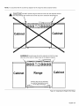
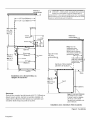
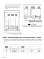
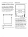
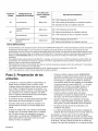
Step 2: Cabinet Preparation
The range is a free standing unit. If the unit is to be
placed adjacent to cabinets, the clearances shown in
Figure 1 are required. The same clearances apply to
island installations, except for the overhead cabinets,
which must have a space wide enough to accept the
flared island hood.
• Any openings in the wall behind the range and in the
floor under the range must be sealed.
• The gas and electrical supply should be within the
zones shown in Figure 3 on page 7.
• When installing against a combustible surface, a High
Shelf or Low Backguard is required. A THERMADOR ®
High Shelf or Low Backguard must be purchased
separately (see chart on page 17).
• When using the Flush Island Trim, THERMADOR
recommends a minimum 12" (305 mm) rear clearance
to a combustible surface (see Figure 1, Cabinet
Clearances). Clearances from non-combustible
materials are not part of the ANSI Z21.1 scope and are
not certified by CSA. Clearances of less than 12"
(305 mm) must be approved by the local codes and/or
by the local authority having jurisdiction.
• When the range is installed against a combustible side
wall a minimum clearance of 5" (127mm) is needed
from the side of the range to the wall.
• Always keep appliance area clear from combustible
materials, gasoline and other flammable vapors and
liquids.
• The maximum depth of overhead cabinets installed on
either side of the hood is 13" (330mm).
• Do not obstruct the flow of combustion and ventilation
air to the unit.
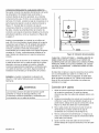
There is a 36" (914mm) minimum clearance required
between the top of the cooking surface and the bottom of
an unprotected cabinet. A 30" (762mm) clearance can be
used when the bottom of the wood or metal cabinet is
protected by not less than 1/4" (6mm) of a flame retardant
material covered with not less than No. 28 MSG sheet
steel, 0.015" (0.38 mm) thick stainless steel, 0.024" (0.61
mm) aluminum, or 0.02" (0.51 mm) thick copper.
Flame retardant materials bear the mark:
UNDERWRITERS LABORATORIES INC. CLASSIFIED
MINERAL AND FIBER BOARDS SURFACE BURNING
CHARACTERISTICS, followed by the flame spread and
smoke ratings. These designations are shown as "FHC
(Flame Spread/Smoke Developed)." Materials with "O"
flame spread ratings are flame retardant. Local codes may
allow other flame spread ratings. It is the responsibility of
the installer to ensure installation is in accordance with
these ratings.
English 4

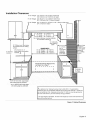
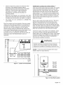
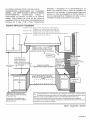
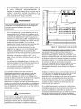
Installation Clearances
30" (762mm) min. m bottom
of Overhead Hood to cooking
surface.
36" (914mm) min. If
18" (457mm) hood contains combustible
minimum materials. A
1
*35 _/8" (911 mm) Min. range height
with eveling legs fully retracted.
*36 ¾" (933mm) Max range height
with leveling legs fully extended
For 30" Ranges {30" (762mm) or 36" (914mm) Wide Hood
{36" (914mm) or 42" (1067mm) for Island
For 36" Ranges {36" (914mm)or 42" (1067mm)Wide Hood
{42" (1067mm) or 48" (1219mm) for Island
)r 48" Ranges {48" (1219mm) 54" (1372mm), or 60" (1524mm) Wide Hood
{54" (1372mm) for Island -................................................_
30" Range
36" Range -- 36" (914mm)
Range -- 48" (1219mm)
Min. distance between overhead cabinets
of combustible material
13" (330mm)_
Max Cabinet_
Depth
RANGE WIDTH
For 30" Ranges -- 30" (762mm)
For 36" Ranges -- 36" (914mm)
For 48" Ranges -- 48" (1219mm)
For Electrical & Gas Supply zones,
see Figure 3a on Page 7.
I- '3
5" (127mm)
min. to
combustible
sidewall
material_
(both sides).
_CAUTION!
See Figure2
36"(914mm) Min
combustible
ig
Surface
1
Cooking J
Surface
A
_ as defined in the "National Fuel Gas Code" (ANSI Z223.1, Current Edition).
£1earances from non-combustible materials are not part of the ANSI Z21.1 scope and
_re not certified by CSA. Clearances of less than 12" (305 mm) must be approved by
!he local codes and/or by the local authority having jurisdiction.
The range height is adjustable. The level of the range top must be at the same level or
rbove the counter top level.
Figure 1: Cabinet Clearances
English 5

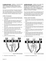
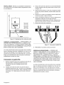
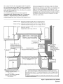
Installation with Low Back or High Shelf
Combustible
_27 %" (702mm)
4_27 1/4"(692mm)
36" (914mm)
min. to_
combustibles
ax 36 ¾"
(933mm)
Min35 _"
(il 1mm)
Materials
10¾"
(273mm',
I--
High Shelf-__-2il__.__ _'
÷
36" & 48" Low Back
30" Low Back Guard
24 %"
(625mm)
24" max.
(606mm)
Front Face
24 ¾"
(629mm)
1'
22"
(559mm)
Back Wall
.41 23" _-
• (584mm) •
as defined in the "National Fuel Gas
"_ode" (ANSI Z223.1, Current Edition).
"_learances from non-combustible materials
_re not part of the ANSI Z21.1 scope and are
_ot certified by CSA. Clearances of less than
12" (305 mm) must be approved by the local
;odes and/or by the local authority having
urisdiction.
Installation with Flush Island Trim
36" (914 mm)
min. to
combustibles
1
Note: For Flush Island
Trim installations,
counter surface should
have a cantilever edge
meeting the back sectior
of the Flush Island Trim
accessory.
I
I
I
Flush Island Trim I
13/16"(21mm) ha _thtI
12" (305mm) min
to combustible_
surface with Flush
Island Trim
Materials_
Note:
With the oven door fully open, the top of the
door extends to 44 %" (1140mm) from the
back wall, behind the range when installed.
Installation must allow ample clearance for
movement around the door when fully
opened.
t
Max 36
(933mm)
Min35 _"
(911mm)
Front Face
Cantilever
If an inner wall is
used under the cantilever
counter top, there should
be a _,/_"(3mm) gap from
the rear of the range to the
inner wall.
Figure 2: Side View
English 6

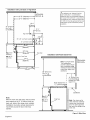
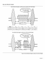
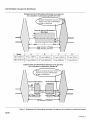
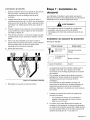
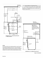
Gas and
Electric Supply
Gas & Electrical Supply Locations for 30" and 36" Dual Fuel Ranges
(51mm) max protrusion
from wall for gas or
electrical supply
Gas & Electrical Supply Zone
30" Models (762mm)
36" Models (914mm)
Model A B C D
30" (762mm) 53/4''(146mm) 187/16'' (468mm) 513/16" (148mm) 215/16"(75mm)
36" (913mm) 81/16"(205mm) 1913/16" (503mm) 81/8" (206mm) 33/16 '' (81mm)
Gas & Electrical Supply Locations for 48" Dual Fuel Ranges
48" Models (1219mm)
Figure 3a: Gas & Electrical Supply Locations for Dual Fuel Ranges
English 7

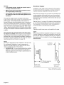
NOTICE:
-- If not already present, install gas shut-off valve in
an easily accessible location.
-- Make sure all users know where and how to shut
off the gas supply to the range.
-- Any opening in the wall behind the appliance and
any opening in the floor under the appliance must
be sealed.
The dual fuel ranges may be connected to the power
supply with a range supply cord kit or by hard-wiring to the
power supply. It is the responsibility of the installer to
provide the proper wiring components (cord or conduit and
wires) and complete the electrical connection as dictated
by local codes and ordinances, and/or the National Electric
Code. The units must be properly grounded. Refer to see
"Step 6: Electrical Requirements, Connection & Grounding"
on page 14 for details. Canadian models have power cord
supplied.
The range must be connected only to the type of gas
for which it is certified. If the range is to be connected to
propane gas, ensure that the propane gas supply tank is
equipped with its own high pressure regulator in addition to
the pressure regulator supplied with the range (see "Step 5:
Gas Requirements and Hookup" on page 13).
NOTE:
The range is designed for flush installation to the back wall.
For a successful installation, it may be necessary to
reposition the gas-supply line and electrical cord as the
range is pushed back to its final position.
-- SUGGESTION: This may be accomplished by carefully
pulling on a rope or twine looped around the gas or
electrical supply line as the range is pushed back into
its final installed position.
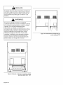
Electrical Supply
Installation of the range must be planned so that rough-in
of terminal block for the receptacle or conduit connection
will allow maximum clearance to the rear of the unit.
When the power supply cord or conduit is connected to the
mating receptacle or terminal block cover, the combined
plug/receptacle or terminal block cover/conduit connector
should protrude no more than 2" (51 mm) from the rear wall.
See Figure 3b.
Refer to Figure 11 on page 15for location of terminal block
on unit. To minimize binding when the unit is connected to
the receptacle or terminal block, orient the receptacle or
conduit connector, and slide back into position.
NOTE:
Canadian models have power cord supplied with range.
NOTE:
When using a 240VAC receptacle having its own housing,
it will be necessary to recess the receptacle's housing into
the rear wall. Mount the receptacle securely to a wall stud,
then seal around the receptacle's housing. Follow all local
electrical codes.
2" (51mm) maximum
when plugged in
I
Power Cord
& Receptacle
2" (51mm)
maximum
I
I
I
I
I
Junction Box
& Conduit
Figure 3b: Wall Connection
English 8

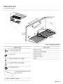
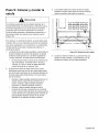
Step 3: Unpacking, Moving
and Placing the Range
CAUTION:
The unit is heavy and should be handled
accordingly. Proper safety equipment such as
gloves and adequate manpower of at least
two people must be used in moving the range
to avoid injury and to avoid damage to the
unit or the floor. Rings, watches, and any
other loose items that may damage the unit
or otherwise might become entangled with
the unit should be removed.
Hidden surfaces may have sharp edges. Use
caution when reaching behind or under
appliance.
CAUTION:
DO NOT lift the range by the oven door's handle, as this
may damage the door hinges and cause the door to fit
incorrectly.
CAUTION:
Do not use a hand truck or appliance dolly on
the back or front of the unit. Handle from the
side only.
,_ Remove all tape and packaging before using the
_11 _1_ appliance. Please, recycle the packaging
material, as all THERMADOR ® appliance
packaging material is recyclable. Never allow
children to play with packaging material.
1. Remove the outer carton and packing materials from
the shipping pallet but leave the adhesive-backed foam
layer over brushed-metal surfaces, to protect finish
from scratches, until the range is installed in its final
position.
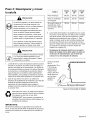
2. The range has an approximate shipping weight as
shown in Chart A. It is recommended that the grates,
griddle plate, burner caps and oven racks be removed
to facilitate handling. This will reduce the weight as
shown in Chart A. Do not remove the griddle
assembly.
Chart A _30 36" 48"
i._ange Range Range
Shipping Weight
Weight without
packing materials
Without doors,
burner caps, front
kick panel and oven
racks
351 Ibs
(159 kg)
228 Ibs
(103 kg)
185 Ibs
(84 kg)
371 Ibs
(168 kg)
270 Ibs
(122 kg)
221 Ibs
(100 kg)
499 Ibs
(226 kg)
403 Ibs
(183 kg)
318 Ibs
(144 kg)
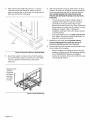
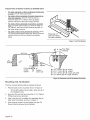
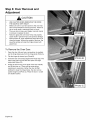
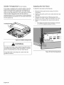
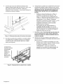
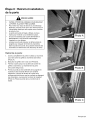
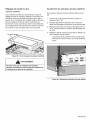
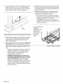
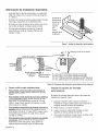
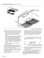
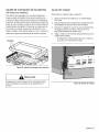
3. The ranges are held to the pallet by four (4) bolts (see
Figure 5). The front kick panel must be removed to
access the bolts in the front of the pallet (see Figure 4).
To remove the Kick Panel, remove the two screws
below the lower corners of the oven cavity and lift the
Kick Panel away from the two projections on the
range's cast base (see also "Kick Panel Adjustment" on
page 26).
-- The electric wire diagrams and schematics are
attached behind the kick panel, and should not be
removed except by a service technician, then
replaced after use.
Remove screws
using a T-20 Torx
screwdriver.
Slightly push
panel up then out
once the screws
have been
\
Figure 4: Remove Kick Panel
English 9

,
,
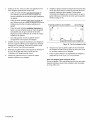
After removing the pallet bolts with two ½" (13mm)
wrenches (one to hold bolt at the bottom while the
other is loosening the nut at the top), the range may be
lifted and removed from the pallet.
@
Pallet
Figure 5: Removal of the Four Shipping Bolts
Due to the weight, a furniture dolly with soft wheels or
an air lift should be used to move this unit. The weight
must be supported uniformly across the bottom
(Figure 6).
,
,
,
After transporting the range by dolly close to its final
location, the range can be tipped back and supported
on the rear legs while the dolly is carefully removed.
THE FLOOR UNDER THE LEGS SHOULD BE
PROTECTED BEFORE PUSHING THE UNIT INTO
POSITION.
• The anti-tip device must be installed ("Step 4:
Installing Anti-Tip Device"), gas and electrical
connections should be made ("Step 5: Gas
Requirements and Hookup" and "Step 6: Electrical
Requirements, Connection & Grounding'), and the
backguard installed ("Step 7: Backguard
Installation (optional)') before the range is placed
in its final position.
• For proper performance, the range must be level.
See "Step 9: Placing and Leveling the Range" on
page 24 for leveling instructions.
Replace the kick panel. It is important that the
screws retaining the kick panel are secure to
prevent accidental access to hot surfaces.
Ensure that the burner caps are correctly seated on the
burner bases of the rangetop.
• Remove all tape and packaging before using the
appliance. Please, recycle the packaging material,
as all THERMADOR ® appliance packaging
material is recyclable. Never allow children to play
with packaging material.
Range must be
uniformly
supported
by braces
provided
on bottom
of range
Figure 6: Dolly Positioning
English 10

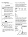
Step 4: Installing Anti-Tip
Device
For all ranges, an anti-tip device must be installed as per
these instructions.
WARNING
RANGE TIPPING HAZARD:
All ranges can tip and injury can result. To prevent
accidental tipping of the range, attach it to the floor,
wall or cabinet by installing the Anti-Tip Device
supplied.
A risk of tip-over may exist if the appliance is not
installed in accordance with these instructions.
If the range is pulled away from the wall for cleaning,
service or for any other reason, ensure that the Anti-Tip
Device is properly re-engaged when the range is pushed
back against the wall. In the event of abnormal usage
(such as a person standing, sitting, or leaning on an
open door), failure to take this precaution can result in
tipping of the range. Personal injury might result from
spilled hot liquids or from the range itself.
WARNING
ELECTRICAL SHOCK HAZARD:
Use extreme caution when drilling holes into the wall
or floor as there may be concealed electrical wires.
Identify the electrical circuits that could be affected
by the installation of the Anti-Tip Device, then turn off
power to these circuits.
Failure to follow these instructions may result in
electrical shock or other personal injury.
Tools Needed for Installation of Anti-Tip Device:
• Screwdriver, Phillips
• Drill, electric or hand
• Measuring tape or ruler
• 1/8" drill bit (wood or metal wall or floor)
• Hammer
• Pencil or other marker
• 3/16" carbide-tipped masonry drill bit (concrete or
concrete block wall or floor)
• 3/16" anchors, drywall or concrete, 4 each (not
required if mounting bracket is being attached to solid
wood or metal).
Thermador
Service Part Qty Description ............
No.
415078 4 Screw, Phillips, #10 x 1½"
647936 1 Anti-Tip Bracket, Floor-
Mounted
Important Installation Information:
• The anti-tip bracket may be attached to a solid wood
cabinet having a minimum wall thickness of ¾"
(19mm).
• The thickness of the wall or floor may require use of
longer screws, available at your local hardware store.
• In all cases, at least two (2) of the bracket mounting
screws must be fastened to solid wood or metal.
• Use appropriate anchors when fastening the mounting
bracket to any material other than hard-wood or metal.
ATTENTION - PROPERTY DAMAGE
• Contact a qualified installer or contractor to determine
the proper method for drilling holes through the wall or
floor material (such as ceramic tile, hardwood, etc.)
• Do not slide the range across an unprotected floor.
• Failure to follow these instructions may result in
damage to wall or floor coverings.
English 11

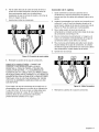
Prepare holes at fastener locations as identified below:
• For walls, wall studs, or floors composed of solid wood
or metal, drill 1/8" (3mm) pilot holes.
• For walls or floors composed of drywall, sheet-rock or
other soft materials, drill 3/16" (5mm) holes to a
minimum depth of 1¾" (45mm), then tap plastic
anchors into each of the holes using a hammer.
• For walls or floors composed of concrete or concrete
block, drill 3/16" (5mm) holes to a minimum depth of
1¾" (45mm), then tap concrete anchors into each of
the holes using a hammer.
• For walls or floors havinq ceramic tile coverinq, drill 3/
16" (5mm) holes through the tile only, then drill into the
material behind the tile as indicated immediately
above.
Range leg will
slide into bracket
slot after installation.
Figure 7: Anti-Tip Bracket
Cabinet <_\°°_"
Wall Line
_.,I X I-.!I From Edge
_$ of Range
/ I I \
Cabinet
Front edge l_lI !_I ×
of right typical--
cabinet ! either side
X = 4½" (114mm) [for 30" range]
X = 6¾" (171mm) [for 36" range]
X = 4½" (116mm) [for 48" range, right side]
X = 31¼"(83mm) [for 48" range, left side]
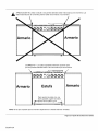
Mounting Anti-Tip Bracket
The floor mounted bracket shall be installed as follows:
,
Place bracket on floor in position shown in Figure 8.
• 30" and 36" bracket may be used in either corner of
the installation area.
2. Secure to floor and wall stud using the (4) 1½" (38mm)
Phillips head screws provided.
3. Later, when the unit is installed, the adjustable leg will
slide under the bracket, as shown in Figure 7.
4. If the range is moved to a new location, the Anti-Tip
Device must be removed and reinstalled.
Figure 8: Placement of Anti-Tip Bracket (Top View)
English 12

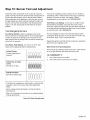
Step 5: Gas Requirements and
Hookup
Verify the type of gas being used at the installation site.
The appliance is shipped from the factory for use with
natural gas. It must be converted for use with propane.
A qualified technician or installer must do the
conversion. Make certain the range matches the type of
gas available at this location.
The field conversion kit for this series of Dual Fuel Ranges
is THERMADOR ® model PLPKIT. Obey all instructions in
PLPKIT for correct conversion of the gas regulator and
settings for the gas valves.
For installation of the appliance at high altitude, up to
10,100 ft. (3,078 m) elevation above sea level, please
consult your local gas company for their recommendation
of the correct orifice sizes and any other necessary
adjustments that will provide proper gas combustion at
specified altitudes.
This appliance has been CSA certified for safe operation
up to an elevation of 10,200 ft (3,109 m) without any
modifications. Exception: For use with propane, the
appliance must be converted per the LP conversion
instructions.
ILCAUTION:
When connecting unit to propane gas, make certain the
propane gas tank is equipped with its own high pressure
regulator in addition to the pressure regulator supplied
with the appliance. The pressure of the gas supplied to
the appliance regulator must not exceed 14" water
column (34.9 mb).
Inlet Connection: 1/2" NPT internal
(Minimum 3/4" dia. flex line)
Supply Pressure: 6" min. to 14" max. water column
(14.9 to 34.9 mb)
Manifold Pressure: 5" water column (12.5 mb)
Propane Gas Requirements:
Inlet Connection: 1/2" NPT internal
(Minimum 3/4" dia. flex line)
Supply Pressure: 1l"min, to 14"max. water column
(27.4 mb to 34.9 mb)
Manifold Pressure: 10" water column (24.9 mb)
WARNING:
Gas line must not come in contact with any components
inside back cover of range.
Hook Up
1. A manual gas shut-off valve must be installed external
to the appliance, in a location accessible from the front,
for the purpose of shutting off the gas supply. The
supply line must not interfere with the back of the unit.
Make sure the gas supply is turned off at the manual
shut-off valve before connecting the appliance.
• The range is supplied with its own pressure
regulator that has been permanently mounted
within the range body.
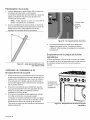
2. Use a ¾" (19mm) flex line to connect between the gas
supply and the appliance gas inlet. The gas supply line
connection is located at the lower right portion of all
range models (see Figure 9 and Figure 10). The
appliance gas inlet connection is ½" (13mm) NPT.
• Use caution to avoid crimping the ¾" (19mm) flex
line when making bends. Suggested length of flex
line is 48" (1219mm); however, please check local
codes for your area's requirements before
installation.
• The gas supply connections shall be made by a
competent technician and in accordance with local
codes or ordinances. In the absence of local
codes, the installation must conform to the National
Fuel Gas Code ANSI Z223.1/NFPA54- current
issue.
3. Always use pipe sealing compound or Teflon ® tape on
the pipe threads, and be careful not to apply excessive
pressure when tightening the fittings.
4. Leak testing of the appliance shall be in accordance
with the following instructions.
• Turn on gas and check supply line connections for
leaks using a soap and water solution.
• Bubbles forming indicate a gas leak. Repair all
leaks immediately after finding them.
ILWARNING:
Do not use a flame of any kind to check for gas
leaks.
English 13

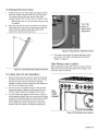
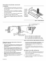
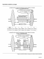
Figure 9: Locationof Gas Supply InletConnection
on 30" and 36" Ranges
)
/
,/
C
E=--IR=
+ ==iii=i
Figure 10: Location of Gas Supplylnlet Connection on 48"
Ranges
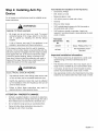
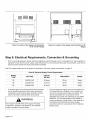
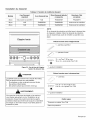
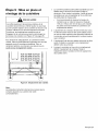
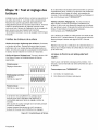
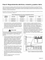
Step 6: Electrical Requirements, Connection & Grounding
• Prior to servicing appliance, always disconnect appliance electrical supply cord, if so equipped, from wall receptacle. If
appliance is hard-wired to power supply, disconnect power to unit by turning off the proper circuit breaker. Lock service
panel to prevent power from being turned ON accidentally.
Dual Fuel range models can be connected or hardwired to the power supply as described on page 15.
Chart B: Electrical Supply circuit Requirements
30" 240/208 VAC 35 Amps 60 Hz. Single
36" 240/208 VAC 35 Amps 60 Hz. Single
48" 240/208 VAC 50 Amps 60 Hz. Single
A neutral supply wire must be provided from the power
source (breaker) because critical range components,
including the surface burner spark re-ignition module,
require 120 VAC to operate safely and properly,
WARNING
An improper 120/240 VAC power supply will cause
malfunction, damage to this appliance, and possibly
create a condition of shock hazard.
If the correct power supply circuit is not provided, it is
the responsibility and obligation of the installer and
user to have proper power supply connected. This
must be accomplished in accordance with all
applicable local codes and ordinances by a qualified
electrician. It is the responsibility of the installer to
ensure compliance of local codes. In the absence of
local codes and ordinances, the power supply
connection shall be in accordance with the National
Electric Code.
English 14

• Observeallgoverningcodesandordinanceswhen
grounding.Intheabsenceofthesecodesor
ordinancesobserveNationalElectricalCodeANSI/
NFPANo.70currentissue.Seethefollowing
informationinthissection,"Step6: Electrical
Requirements, Connection & Grounding", for
grounding method.
• Electrical wiring diagrams and schematics have been
placed in the kick panel area of the range for access by
a qualified service technician (see Figure 4 on page 9).
• The ranges are to be connected to a 240/208 VAC
power supply.
Dual Fuel models must be connected to the power supply
utilizing one of the following methods. For all methods of
connection, the length of the cord or conduit/wiring must
allow the unit to be slid completely out of the cabinet
without having to unplug or disconnect the unit from the
power supply. Recommended minimum free length of cord
or conduit is 4ft (1.2m). Electrical installations and
grounding must be in accordance with all local codes and
ordinances, and/or the National Electric Code, as
applicable.
o0
03
C
1_3_J
T
• I
/
/
/
I
/'
ll.,
_rminal B5 :k
Cover
u
c----,,
Figure 11: Location of Terminal Block
PERMANENT CONNECTION/HARD WIRING) --
Units may be hard wired to the power supply. The installer
must provide approved flexible aluminum conduit, 3/4"
(19mm) trade size, maximum 6ft (1.8m)long. Locate the
terminal block on the rear of the unit and remove cover
(refer to Figure 11). The conduit must be installed to the
terminal block using an approved conduit connector. The
free end of the conduit must be connected to a terminal
block provided in the electrical supply zone, as shown in
Figure 3a on page 7.
Mount a strain relief (not provided) into the 1" (25.4mm)
diameter hole located below the terminal block (see
Figure 12). Wiring for the unit is to be brought into the
terminal block through the conduit and through the strain
relief. The ends of the wiring must have 1/4" (6mm) faston
closed-loop lugs attached, preferably soldered in place.
Make the connections to the terminal block provided.
If aluminum supply wiring exists in the installation, splice
the aluminum house wiring with appropriate-thickness
gauge copper wire for adapting to the range, using special
connectors designed and certified for joining copper and
aluminum wire. Follow the connector manufacturer's
recommended installation procedure.
, WARNING:
Improper connection of aluminum house wiring can
result in a fire or shock hazard. Use only connectors
designed and certified for connecting to aluminum wire.
Installer -- show the owner the location of the circuit
breaker. Mark it for easy reference.
Terminal Block
|
|
Strair_ Relief
\
Figure 12: Strain Relief Location
English 15

4-CONDUCTOR CORD -- NORMALLY, A UNIT MUST BE
CONNECTED TO THE POWER SUPPLY WITH A 3-
POLE, 4-CONDUCTOR CORD KIT RATED 125/250
VOLTS, 50 AMPERES, AND MARKED FOR USE WITH
RANGES.
The cord kit must be attached to the range terminal block
with a strain relief which will fit a 1" (25.4mm) diameter
hole. If not already equipped, the cord must also have 1/4"
(6mm) faston closed-loop lugs attached to the free ends of
the individual conductors, preferably soldered in place.
4-Wire Connection
1. Remove upper nuts only from the terminal block studs.
Do not remove lower nuts which secure range internal
wiring leads.
2. Mount strain relief (not provided with range) into the 1"
(25.4mm) diameter hole in the back panel located
below the terminal block (see Figure 12). Route wires
up through strain relief.
3. Secure the neutral, grounded wire of the supply circuit,
to the center stud of the terminal block with nut (see
Figure 13).
4. Secure the L1 (black) and L2 (red) power leads to the
outside terminal studs (brass colored) with nuts.
5. Remove green ground screw located beneath the
terminal block. Discard white wire.
6.
Secure the bare copper ground lead to the range
chassis using the ground screw previously used for the
white wire. Be sure that neutral and ground terminals
do not touch.
7. Tighten all connections securely.
3-CONDUCTOR CORD -- WHERE LOCAL CODES AND
ORDINANCES PERMIT GROUNDING THROUGH
NEUTRAL, AND CONVERSION OF SUPPLY TO 4 WIRE
IS IMPRACTICAL, UNIT MAY BE CONNECTED TO THE
POWER SUPPLY WITH A 3-POLE, 3-CONDUCTOR
CORD KIT RATED 125/250 VOLTS, 50 AMPERES, AND
MARKED FOR USE WITH RANGES.
The cord kit must be attached to the range back panel with
a strain relief which will fit a 1" (25.4mm) diameter hole. If
not already equipped, the cord must also have 1/4" (6mm)
faston closed-loop lugs attached to the free ends of the
individual conductors, preferably soldered in place.
3-Wire Lead Connection
,
Remove upper nuts only from the terminal block studs.
Do not remove nuts which secure range internal wiring
leads,
2. Mount strain relief (not provided with range) into the 1"
(25.4mm) diameter hole in the back panel located
below the terminal block (see Figure 12). Route wires
up through strain relief.
3. Secure the neutral, grounded wire of the supply circuit,
to the center stud (silver colored) of the terminal block
(see Figure 14).
4. Secure the L1 (black) and L2 (red) power leads to the
outside corresponding terminal block studs (brass
colored).
5. Secure one end of the mounted looped neutral wire,
located beneath terminal block, to the center stud of
the terminal block with nut and keep the other end of
the wire screwed into the back of the range.
6. Tighten nuts securely.
,
E3
Figure 13: 4-Wire Connection
Reinstall the Terminal Block Cover.
,
Figure 14: 3-Wire Connection
Reinstall the Terminal Block Cover.
English 16

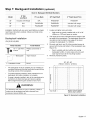
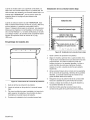
Step 7: Backguard Installation (optional)
30" Included with Range N/A PA30GHSH PA30GITH
36" N/A PA36GLBH PA36GHSH Included with range
48" N/A PA48GLBH PA48GHSH Included with range
Installation methods will vary upon need. Before you begin
read these instructions carefully. Observe all local codes
and ordinances.
Backsplash Installation
(PA [30,36, 48] JBS)
10 - 1" (25.4mm) Phillips screwdriver or
screws drill
_'_-_-1 1 - Backsplash Tape measure
1 - Installation Guide Pencil
The backsplash must be installed prior to installing an
overhead hood given that the hood shell covers the top
mounting screws of the backsplash.
To protect against scratches, leave protective film on
backsplash until after installation is complete.
If range is already installed, refer to the manufacturer's
instructions to disconnect gas and power supplies.
Move range forward to gain access to rear of unit.
WARNING
To reduce the risk of fire or injury to persons, check to
make sure all packaging has been removed from
accessory devices before use.
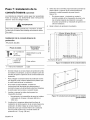
1. Locate and lightly mark wall studs.
• Wall studs are usually installed with a 16" or 24"
(406mm or 1372mm) space on center.
2. The height of the hood will determine the height of the
top edge of the backsplash. The backsplash should be
mounted so that the bottom rear edge of the hood
overlaps the backsplash 1½" (38mm).
3. Per each wall stud, use (2) of the provided screws to
secure both the top and bottom of the backsplash (see
Figure 15).
• Due to variable wall stud widths and varying
backsplash widths, in some cases only one wall
stud may be found at the mounting location.
4. Remove protective plastic.
30", 36", 48"
(760mm, 913mm, 1218mm)
I "T'° ....
!;o;
iI i
l= i
iI i
l= i
II I
A I I I
E ;, ,
I I I
/E /,',
I_ /1,', 1,
1 l"
ii I
iolo °
WallStud
i_ j II m
I_ I II I
II I II J
I_ I II I
I_ I II J
It I II l
I_ I II I
II I II I
li I II I
I_ I II J
I_ I II J
I_ I II t
I_ I II t
I_ I II l
I_ I II l
It I II I
li J II _
I_ J II l
Space screws evenly
across top & bottom
Figure 15: Backsplash Installation
English 17

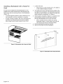
Installing a Backsplash with a Keep Hot
Shelf
A hood can be installed first if the Backsplash is to be
installed with a Keep Hot Shelf given that the Keep Hot
Shelf covers the top mounting screws of the Backsplash
(Figure 16).
• To protect against scratches, leave protective film on
the backsplash until after installation is complete.
• If range is already installed, refer to the manufacturer's
instructions to disconnect gas and power supplies.
Move range forward to gain access to rear of unit.
1. Locate wall studs.
• Wall studs are usually installed with a 16" (406mm)
or 24" (1372mm)space on center.
2. The height of the hood will determine the height of the
top edge of the backsplash. The backsplash should be
mounted so that the bottom rear edge of the Keep Hot
Shelf overlaps the backsplash 1½" (38mm).
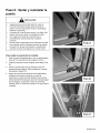
3. At the locations indicated in Figure 17, mount the lower
shelf brackets included with the Keep Hot Shelf
through the Backsplash and into the wall studs.
• Due to variable wall stud widths and varying
backsplash widths, in some cases, only one wall
stud may be found at the mounting location.
4. Remove backsplash protective covering.
5. Start with the Keep Hot Shelf Installation.
Figure 16: Backsplash with a Keep Hot Shelf
I
,
I
I
I
I _ __._,____
i •
41
Figure 17: Backsplash with a Keep Hot Shelf
English 18
La page est en cours de chargement...
La page est en cours de chargement...
La page est en cours de chargement...
La page est en cours de chargement...
La page est en cours de chargement...
La page est en cours de chargement...
La page est en cours de chargement...
La page est en cours de chargement...
La page est en cours de chargement...
La page est en cours de chargement...
La page est en cours de chargement...
La page est en cours de chargement...
La page est en cours de chargement...
La page est en cours de chargement...
La page est en cours de chargement...
La page est en cours de chargement...
La page est en cours de chargement...
La page est en cours de chargement...
La page est en cours de chargement...
La page est en cours de chargement...
La page est en cours de chargement...
La page est en cours de chargement...
La page est en cours de chargement...
La page est en cours de chargement...
La page est en cours de chargement...
La page est en cours de chargement...
La page est en cours de chargement...
La page est en cours de chargement...
La page est en cours de chargement...
La page est en cours de chargement...
La page est en cours de chargement...
La page est en cours de chargement...
La page est en cours de chargement...
La page est en cours de chargement...
La page est en cours de chargement...
La page est en cours de chargement...
La page est en cours de chargement...
La page est en cours de chargement...
La page est en cours de chargement...
La page est en cours de chargement...
La page est en cours de chargement...
La page est en cours de chargement...
La page est en cours de chargement...
La page est en cours de chargement...
La page est en cours de chargement...
La page est en cours de chargement...
La page est en cours de chargement...
La page est en cours de chargement...
La page est en cours de chargement...
La page est en cours de chargement...
La page est en cours de chargement...
La page est en cours de chargement...
La page est en cours de chargement...
La page est en cours de chargement...
La page est en cours de chargement...
La page est en cours de chargement...
La page est en cours de chargement...
La page est en cours de chargement...
La page est en cours de chargement...
La page est en cours de chargement...
La page est en cours de chargement...
La page est en cours de chargement...
La page est en cours de chargement...
La page est en cours de chargement...
La page est en cours de chargement...
La page est en cours de chargement...
La page est en cours de chargement...
La page est en cours de chargement...
La page est en cours de chargement...
La page est en cours de chargement...
La page est en cours de chargement...
La page est en cours de chargement...
La page est en cours de chargement...
La page est en cours de chargement...
-
 1
1
-
 2
2
-
 3
3
-
 4
4
-
 5
5
-
 6
6
-
 7
7
-
 8
8
-
 9
9
-
 10
10
-
 11
11
-
 12
12
-
 13
13
-
 14
14
-
 15
15
-
 16
16
-
 17
17
-
 18
18
-
 19
19
-
 20
20
-
 21
21
-
 22
22
-
 23
23
-
 24
24
-
 25
25
-
 26
26
-
 27
27
-
 28
28
-
 29
29
-
 30
30
-
 31
31
-
 32
32
-
 33
33
-
 34
34
-
 35
35
-
 36
36
-
 37
37
-
 38
38
-
 39
39
-
 40
40
-
 41
41
-
 42
42
-
 43
43
-
 44
44
-
 45
45
-
 46
46
-
 47
47
-
 48
48
-
 49
49
-
 50
50
-
 51
51
-
 52
52
-
 53
53
-
 54
54
-
 55
55
-
 56
56
-
 57
57
-
 58
58
-
 59
59
-
 60
60
-
 61
61
-
 62
62
-
 63
63
-
 64
64
-
 65
65
-
 66
66
-
 67
67
-
 68
68
-
 69
69
-
 70
70
-
 71
71
-
 72
72
-
 73
73
-
 74
74
-
 75
75
-
 76
76
-
 77
77
-
 78
78
-
 79
79
-
 80
80
-
 81
81
-
 82
82
-
 83
83
-
 84
84
-
 85
85
-
 86
86
-
 87
87
-
 88
88
-
 89
89
-
 90
90
-
 91
91
-
 92
92
-
 93
93
-
 94
94


Thermador PRD366GHC/10 Guide d'installation
- Catégorie
- Cuisinières
- Taper
- Guide d'installation
- Ce manuel convient également à
dans d''autres langues
Documents connexes
-
Thermador PRD305PH Guide d'installation
-
-
-
-
-
-
-
-
-
Autres documents
-
Maytag MER6771AAW Guide d'installation
-
 Inoxia BSATC-S Guide d'installation
-
HDX 128974 Manuel utilisateur
-
Craftsman 706331460 Le manuel du propriétaire
-
Avanti WDB20Y0W Mode d'emploi
-
-
Legrand Nonmetallic Raceway - NM1, NMW1 Guide d'installation
-
-
Frigidaire FES355ABB Le manuel du propriétaire
-
Fellowes LEVADO Le manuel du propriétaire
