
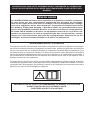
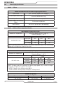
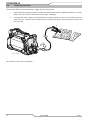
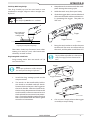
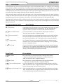
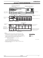
40
120-
240V
esab.com
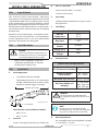
OUTPUT MAX OUTPUT
VOLTAGE
Art # A-14036_AB
INPUT POWER
Revision: AB Issue Date: 13 December, 2019 Manual No.: 0-5557
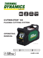
OPERATING
MANUAL
CUTMASTER® 40
PLASMA CUTTING SYSTEM

WE APPRECIATE YOUR BUSINESS!
Congratulations on your new Thermal Dynamics product. We are proud to have you as our customer
and will strive to provide you with the best service and reliability in the industry. This product is
backed by our extensive warranty and world-wide service network. To locate your nearest distributor
or service agency call 1-800-426-1888, or visit us on the web at www.esab.com.
This Operating Manual has been designed to instruct you on the correct use and operation of your
Thermal Dynamics product. Your satisfaction with this product and its safe operation is our ultimate
concern. Therefore please take the time to read the entire manual, especially the Safety Precautions.
They will help you to avoid potential hazards that may exist when working with this product.
YOU ARE IN GOOD COMPANY!
The Brand of Choice for Contractors and Fabricators Worldwide.
Thermal Dynamics is a Global Brand of manual and automation Plasma Cutting Products for ESAB.
We distinguish ourselves from our competition through market-leading, dependable products
that have stood the test of time. We pride ourselves on technical innovation, competitive prices,
excellent delivery, superior customer service and technical support, together with excellence in
sales and marketing expertise.
Above all, we are committed to developing technologically advanced products to achieve a safer
working environment within the welding industry.

i
Plasma Cutting Power Supply
CutMaster® 40
SL60™ 1Torch™
Operating Manual Number 0-5557
Published by:
ESAB Group Incorporated
2800 Airport Rd.
Denton, Texas 76207
www.esab.com
© Copyright 2019 by
Thermal Dynamics an ESAB brand.
All rights reserved.
Reproduction of this work, in whole or in part, without written permission of the
publisher is prohibited.
The publisher does not assume and hereby disclaims any liability to any party for
any loss or damage caused by any error or omission in this Manual, whether such
error results from negligence, accident, or any other cause.
For Material Print Specications, refer to document 47x1961
Original Publication Date: 15 November, 2019
Revision Date: 13 December, 2019
See website for Warranty Information.
Record the following information for Warranty purposes:
Where Purchased:_______________________________ _____________________
Purchase Date:__________________________ ____________________________
Power Supply Serial #:_______________________________ _________________
Torch Serial #:______________________________ _________________________
!!
WARNING
Read and understand this entire Manual and your employer’s safety practices before installing, operating, or
servicing the equipment.
While the information contained in this Manual represents the Manufacturer’s best judgment, the Manufacturer
assumes no liability for its use.
i

Be sure this information reaches the operator.
You can get extra copies through your supplier.
CAUTION
These INSTRUCTIONS are for experienced operators. If you are not fully
familiar with the principles of operation and safe practices for arc welding
and cutting equipment, we urge you to read our booklet, “Precautions and
Safe Practices for Arc Welding, Cutting, and Gouging,” Form 52-529. Do
NOT permit untrained persons to install, operate, or maintain this equip-
ment. Do NOT attempt to install or operate this equipment until you have
read and fully understand these instructions. If you do not fully understand
these instructions, contact your supplier for further information. Be sure to
read the Safety Precautions before installing or operating this equipment.
USER RESPONSIBILITY
This equipment will perform in conformity with the description thereof contained in this manual and accompanying labels
and/or inserts when installed, operated, maintained and repaired in accordance with the instructions provided. This
equipment must be checked periodically. Malfunctioning or poorly maintained equipment should not be used. Parts that
are broken, missing, worn, distorted or contaminated should be replaced immediately. Should such repair or replacement
become necessary, the manufacturer recommends that a telephone or written request for service advice be made to the
Authorized Distributor from whom it was purchased.
This equipment or any of its parts should not be altered without the prior written approval of the manufacturer. The user
of this equipment shall have the sole responsibility for any malfunction which results from improper use, faulty mainte-
nance, damage, improper repair or alteration by anyone other than the manufacturer or a service facility designated by
the manufacturer.
!
READ AND UNDERSTAND THE INSTRUCTION MANUAL BEFORE INSTALLING OR
OPERATING.
PROTECT YOURSELF AND OTHERS!

ASSUREZ-VOUS QUE CETTE INFORMATION EST DISTRIBUÉE À L’OPÉRATEUR.
VOUS POUVEZ OBTENIR DES COPIES SUPPLÉMENTAIRES CHEZ VOTRE FOUR-
NISSEUR.
MISE EN GARDE
Les INSTRUCTIONS suivantes sont destinées aux opérateurs qualiés seulement.
Si vous n’avez pas une connaissance approfondie des principes de fonctionne-
ment et des règles de sécurité pour le soudage à l’arc et l’équipement de coupage,
nous vous suggérons de lire notre brochure « Precautions and Safe Practices for
Arc Welding, Cutting and Gouging, » Brochure 0-5407. Ne permettez PAS aux per-
sonnes non qualiées d’installer, d’opérer ou de faire l’entretien de cet équipement.
Ne tentez PAS d’installer ou d’opérer cet équipement avant de lire et de bien com-
prendre ces instructions. Si vous ne comprenez pas bien les instructions, commu-
niquez avec votre fournisseur pour plus de renseignements. Assurez-vous de lire
les Règles de Sécurité avant d’installer ou d’opérer cet équipement.
RESPONSABILITÉS DE L’UTILISATEUR
Cet équipement opérera conformément à la description contenue dans ce manuel, les étiquettes d’accompagne-
ment et/ou les feuillets d’information si l’équipement est installé, opéré, entretenu et réparé selon les instructions
fournies. Vous devez faire une vérication périodique de l’équipement. Ne jamais utiliser un équipement qui ne
fonctionne pas bien ou n’est pas bien entretenu. Les pièces qui sont brisées, usées, déformées ou contaminées
doivent être remplacées immédiatement. Dans le cas où une réparation ou un remplacement est nécessaire, il
est recommandé par le fabricant de faire une demande de conseil de service écrite ou par téléphone chez le
Distributeur Autorisé de votre équipement.
Cet équipement ou ses pièces ne doivent pas être modiés sans permission préalable écrite par le fabricant.
L’utilisateur de l’équipement sera le seul responsable de toute défaillance résultant d’une utilisation incorrecte,
un entretien fautif, des dommages, une réparation incorrecte ou une modication par une personne autre que le
fabricant ou un centre de service désigné par le fabricant.
!
ASSUREZ-VOUS DE LIRE ET DE COMPRENDRE LE MANUEL D’UTILISATION
AVANT D’INSTALLER OU D’OPÉRER L’UNITÉ.
PROTÉGEZ-VOUS ET LES AUTRES!

This Page Intentionally Blank

TABLE OF CONTENTS
SECTION 1: GENERAL INFORMATION............................................................ 9
1.01 Notes, Cautions and Warnings ................................................................................... 9
SECTION 1 : INFORMATIONS GÉNÉRALES ................................................... 11
1.01 Remarques, avertissements et mises en garde ........................................................ 11
SECTION 2 SYSTEM: INTRODUCTION ......................................................... 13
2.01 How To Use This Manual ..........................................................................................13
2.02 Equipment Identication ......................................................................................... 13
2.03 Receipt Of Equipment ..............................................................................................13
2.04 Power Supply Specications ....................................................................................14
2.04.01 1 Phase 14
2.04.02 Additional Power Supply Specications 14
2.04.03 Generator Recommendations 15
2.05 Input Wiring Specications ......................................................................................15
2.06 Power Supply Features ............................................................................................16
SECTION 2 TORCH: INTRODUCTION ........................................................... 19
2T.01 Scope of Manual ...................................................................................................... 19
2T.02 General Description ................................................................................................. 19
2T.03 Specications ......................................................................................................... 19
SECTION 3 SYSTEM: INSTALLATION ........................................................... 21
3.01 Unpacking ............................................................................................................... 21
3.02 Lifting Options ......................................................................................................... 21
3.03 Gas Connections ...................................................................................................... 22
3.04 Primary Input Power Connections ........................................................................... 23
3.05 Work Lead Connections ........................................................................................... 24
SECTION 3 TORCH:
INSTALLATION ......................................................................................... 25
3T.01 Torch Connections....................................................................................................25
SECTION 4 SYSTEM: OPERATION ............................................................... 27
4.01 Front Panel Controls / Features ................................................................................ 27
4.02 Preparations for Operation ......................................................................................28
SECTION 4 TORCH: OPERATION .................................................................. 31
4T.01 Torch Parts Selection ............................................................................................... 31
4T.02 Hand Torch Operation .............................................................................................. 31
4T.03 Gouging...................................................................................................................35
4T.04 PATENT INFORMATION .............................................................................................37

TABLE OF CONTENTS
SECTION 5 SYSTEM: SERVICE ..................................................................... 39
5.01 General Maintenance ..............................................................................................39
5.02 Maintenance Schedule ............................................................................................ 39
5.03 Common Faults ........................................................................................................ 40
5.04 Fault Indicator .........................................................................................................41
5.05 Basic Troubleshooting Guide ....................................................................................42
5.06 Power Supply Basic Parts Replacement ................................................................... 44
SECTION 5 TORCH: SERVICE ...................................................................... 45
5T.01 General Maintenance .............................................................................................. 45
5T.02 Inspection and Replacement of Consumable Torch Parts ......................................... 46
SECTION 6: PARTS LISTS ........................................................................... 47
6.01 Introduction ............................................................................................................47
6.02 Ordering Information ..............................................................................................47
6.03 Power Supply System Replacement .........................................................................47
6.04 Replacement Power Supply Parts ............................................................................ 48
6.05 Options and Accessories ..........................................................................................48
6.06 External Replacement Parts ................................................................................... 49
6.07 Replacement Parts for SL60 Hand Torch .................................................................. 50
6.08 Replacement Parts for SL60QD Hand Torch ............................................................. 51
6.09 Torch Consumable Parts (SL60) ................................................................................52
APPENDIX 1: DATA TAG INFORMATION ...................................................... 53
APPENDIX 2: TORCH PIN OUT DIAGRAMS ................................................ 54
APPENDIX 3: TORCH CONNECTION DIAGRAMS ........................................... 55
APPENDIX 4: PUBLICATION HISTORY ........................................................ 56

CUTMASTER 40
0-5557 GENERAL INFORMATION
9
SECTION 1: GENERAL INFORMATION
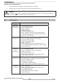
1.01 Notes, Cautions and Warnings
Throughout this manual, notes, cautions, and warnings are used to highlight important information.
These highlights are categorized as follows:
NOTE!
An operation, procedure, or background information which requires additional emphasis or is helpful in
ecient operation of the system.
!!
CAUTION
A procedure which, if not properly followed, may cause damage to the equipment.
!!
WARNING
A procedure which, if not properly followed, may cause injury to the operator or others in the operating area.
WARNING
Gives information regarding possible electrical shock injury.

CUTMASTER 40
GENERAL INFORMATION 0-5557
10
AVERTISSEMENT
WARNING
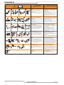
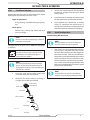
1. Cutting sparks can cause explosion
or fire.
1.1 Do not cut near flammables.
1.2 Have a fire extinguisher nearby and
ready to use.
1.3 Do not use a drum or other closed
container as a cutting table.
2. Plasma arc can injure and burn;
point the nozzle away from
yourself. Arc starts instantly when
triggered.
2.1 Turn o power before disassembling
torch.
2.2 Do not grip the workpiece near the
cutting path.
2.3 Wear complete body protection.
3. Hazardous voltage. Risk of electric
shock or burn.
3.1 Wear insulating gloves. Replace
gloves when wet or damaged.
3.2 Protect from shock by insulating
yourself from work and ground.
3.3 Disconnect power before servicing.
Do not touch live parts.
4. Plasma fumes can be hazardous.
4.1 Do not inhale fumes.
4.2 Use forced ventilation or local
exhaust to remove the fumes.
4.3 Do not operate in closed spaces.
Remove fumes with ventilation.
6. Become trained.
Only qualified personnel should
operate this equipment. Use torches
specified in the manual. Keep
non-qualified personnel and children
away.
5. Arc rays can burn eyes and injure
skin.
5.1 Wear correct and appropriate
protective equipment to protect
head, eyes, ears, hands, and body.
Button shirt collar. Protect ears from
noise. Use welding helmet with the
correct shade of filter.
7. Do not remove, destroy, or cover
this label.
Replace if it is missing, damaged,
or worn.
1. Les étincelles de coupage peuvent
provoquer une explosion ou un
incendie.
1.1 Ne pas couper près des matières
inflammables.
1.2 Un extincteur doit être à proximité
et prêt à être utilisé.
1.3 Ne pas utiliser un fût ou un autre
contenant fermé comme table de
coupage.
2. L’arc plasma peut blesser et brûler;
éloigner la buse de soi. Il s’allume
instantanément quand on l’amorce.
2.1 Couper l’alimentation avant de
démonter la torche.
2.2 Ne pas saisir la pièce à couper de la
trajectoire de coupage.
2.3 Se protéger entièrement le corps.
3. Tension dangereuse. Risque de
choc électrique ou de brûlure.
3.1 Porter des gants isolants. Remplacer
les gants quand ils sont humides ou
endommagés.
3.2 Se protéger contre les chocs en
s’isolant de la pièce et de la terre.
3.3 Couper l’alimentation avant
l’entretien. Ne pas toucher les pièces
sous tension.
4. Les fumées plasma peuvent être
dangereuses.
4.1 Ne pas inhaler les fumées.
4.2 Utiliser une ventilation forcée ou un
extracteur local pour dissiper les
fumées.
4.3 Ne pas couper dans des espaces clos.
Chasser les fumées par ventilation.
5. Les rayons d’arc peuvent brûler les
yeux et blesser la peau.
5.1 Porter un bon équipement de
protection pour se protéger la tête,
les yeux, les oreilles, les mains et le
corps. Boutonner le col de la chemise.
Protéger les oreilles contre le bruit.
Utiliser un masque de soudeur avec
un filtre de nuance appropriée.
6. Suivre une formation.
Seul le personnel qualifié a
le droit de faire fonctionner cet
équipement. Utiliser exclusivement
les torches indiquées dans le manual.
Le personnel non qualifié et les
enfants doivent se tenir à l’écart.
7. Ne pas enlever, détruire ni couvrir
cette étiquette.
La remplacer si elle est absente,
endommagée ou usée.
Art # A-13294

CUTMASTER 40
0-5557 GENERAL INFORMATION
11
SECTION 1 : INFORMATIONS GÉNÉRALES
1.01 Remarques, avertissements et mises en garde
Le présent manuel est ponctué de remarques, d’avertissements et de mises en garde qui attirent
l’attention sur des informations importantes. Ces repères sont classés comme suit :
REMARQUE:
Fonction, procédé ou renseignement de base qui nécessite une plus grande attention ou contribue au
bon fonctionnement du système.
!!
ATTENTION
Procédé qui, s’il n’est pas suivi correctement, peut endommager l’équipement.
!!
AVERTISSEMENT
Procédé qui, s’il n’est pas suivi correctement, peut causer des lésions à l’utilisateur ou aux personnes
dans la zone d’exploitation.
AVERTISSEMENT
Fournit des renseignements relatifs à d’éventuelles blessures se devant à une décharge électrique.

CUTMASTER 40
GENERAL INFORMATION 0-5557
12
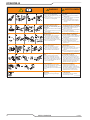
AVERTISSEMENT
WARNING
1. Cutting sparks can cause explosion
or fire.
1.1 Do not cut near flammables.
1.2 Have a fire extinguisher nearby and
ready to use.
1.3 Do not use a drum or other closed
container as a cutting table.
2. Plasma arc can injure and burn;
point the nozzle away from
yourself. Arc starts instantly when
triggered.
2.1 Turn o power before disassembling
torch.
2.2 Do not grip the workpiece near the
cutting path.
2.3 Wear complete body protection.
3. Hazardous voltage. Risk of electric
shock or burn.
3.1 Wear insulating gloves. Replace
gloves when wet or damaged.
3.2 Protect from shock by insulating
yourself from work and ground.
3.3 Disconnect power before servicing.
Do not touch live parts.
4. Plasma fumes can be hazardous.
4.1 Do not inhale fumes.
4.2 Use forced ventilation or local
exhaust to remove the fumes.
4.3 Do not operate in closed spaces.
Remove fumes with ventilation.
6. Become trained.
Only qualified personnel should
operate this equipment. Use torches
specified in the manual. Keep
non-qualified personnel and children
away.
5. Arc rays can burn eyes and injure
skin.
5.1 Wear correct and appropriate
protective equipment to protect
head, eyes, ears, hands, and body.
Button shirt collar. Protect ears from
noise. Use welding helmet with the
correct shade of filter.
7. Do not remove, destroy, or cover
this label.
Replace if it is missing, damaged,
or worn.
1. Les étincelles de coupage peuvent
provoquer une explosion ou un
incendie.
1.1 Ne pas couper près des matières
inflammables.
1.2 Un extincteur doit être à proximité
et prêt à être utilisé.
1.3 Ne pas utiliser un fût ou un autre
contenant fermé comme table de
coupage.
2. L’arc plasma peut blesser et brûler;
éloigner la buse de soi. Il s’allume
instantanément quand on l’amorce.
2.1 Couper l’alimentation avant de
démonter la torche.
2.2 Ne pas saisir la pièce à couper de la
trajectoire de coupage.
2.3 Se protéger entièrement le corps.
3. Tension dangereuse. Risque de
choc électrique ou de brûlure.
3.1 Porter des gants isolants. Remplacer
les gants quand ils sont humides ou
endommagés.
3.2 Se protéger contre les chocs en
s’isolant de la pièce et de la terre.
3.3 Couper l’alimentation avant
l’entretien. Ne pas toucher les pièces
sous tension.
4. Les fumées plasma peuvent être
dangereuses.
4.1 Ne pas inhaler les fumées.
4.2 Utiliser une ventilation forcée ou un
extracteur local pour dissiper les
fumées.
4.3 Ne pas couper dans des espaces clos.
Chasser les fumées par ventilation.
5. Les rayons d’arc peuvent brûler les
yeux et blesser la peau.
5.1 Porter un bon équipement de
protection pour se protéger la tête,
les yeux, les oreilles, les mains et le
corps. Boutonner le col de la chemise.
Protéger les oreilles contre le bruit.
Utiliser un masque de soudeur avec
un filtre de nuance appropriée.
6. Suivre une formation.
Seul le personnel qualifié a
le droit de faire fonctionner cet
équipement. Utiliser exclusivement
les torches indiquées dans le manual.
Le personnel non qualifié et les
enfants doivent se tenir à l’écart.
7. Ne pas enlever, détruire ni couvrir
cette étiquette.
La remplacer si elle est absente,
endommagée ou usée.
Art # A-13294

CUTMASTER 40
0-5557 INTRODUCTION
13
SECTION 2 SYSTEM: INTRODUCTION
2.01 How To Use This Manual
This Owner’s Manual applies to just product(s) listed on page i.
To ensure safe operation, read the entire manual, including the chapter on safety instructions and
warnings.
Additional copies of this manual may be purchased by contacting Thermal Dynamics at the address
and phone number in your area listed on back cover of this manual. Include the Operating Manual
number and equipment identication numbers.
Electronic copies of this manual can also be downloaded at no charge in Acrobat PDF format by go-
ing to the ESAB web site listed below and clicking on "Product Support" / "ESAB Documentation": /
"Download Library", then navigate to "Plasma Equipment" and then "Manual".
http://www.esab.com
2.02 Equipment Identication
The unit’s identication number (specication or part number), model, and serial number usually appear
on a data tag attached to the bottom. Equipment which does not have a data tag such as torch and
cable assemblies are identied only by the specication or part number printed on loosely attached
card or the shipping container. Record these numbers on the bottom of page i for future reference.
2.03 Receipt Of Equipment
When you receive the equipment, check it against the invoice to make sure it is complete and inspect
the equipment for possible damage due to shipping. If there is any damage, notify the carrier imme-
diately to le a claim. Furnish complete information concerning damage claims or shipping errors to
the location in your area listed on the back cover of this manual.
Include all equipment identication numbers as described above, along with a full description of the
parts in error.
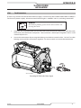
Art# A-14343
Included items:
• CutMaster 40 Power Supply
• SL60™ Torch and Leads
• Work Lead with Work Clamp
• Spare Parts Kit ( 2 Electrodes, 2 Stando
Tips, 1 Gouging Tip, 1 Shield Cap and
1 Shield cup)
• 50 Amp to 20 Amp Adapter
• 20 Amp to 15 Amp Adapter (not shown)
• Operating Manual (not shown)
• Quick Start Guide
Move the equipment to the installation site before
un-boxing the unit. Use care to avoid damaging
the equipment when opening the box.

CUTMASTER 40
INTRODUCTION 0-5557
14
2.04 Power Supply Specications
2.04.01 1 Phase
CM 40 120-240 VAC 1 Phase Power Supply Specications
Input Power 120 - 240 VAC, Single Phase, 50/60 Hz
1 Phase Input Power Cable
Power Supply includes 9' single phase 8AWG 3/C input
cable with NEMA 6-50P Plug.
Output Current 15 - 40 Amps, Continuously Adjustable
Power Supply Gas Filtering
Ability
Particulates to 5 Microns
Inlet Pressure 90-125 PSI (6.2-8.6 bar / 620-862 Kpa)
2.04.02 Additional Power Supply Specications
CM 40 Power Supply Duty Cycle *
Ambient Air Temperature
Duty Cycle Ratings @ 40° C (104° F)
Operating Range 0° - 50° C
Rating
208-240 VAC Units
Duty Cycle* 40% 60% 100%
Current
40 Amps 30 Amps 20 Amps
DC Voltage
135 130 135
* NOTE: The duty cycle will be reduced if the primary input power (AC) is low or the output
voltage (DC) is higher than shown in this chart.
CM 40 Power Supply Duty Cycle *
Ambient Air Temperature
Duty Cycle Ratings @ 40° C (104° F)
Operating Range 0° - 50° C
Rating
120 VAC Units
Duty Cycle* 30% 60% 100%
Current
27 Amps** 20 Amps 15 Amps
DC Voltage
92 93 89
* NOTE: The duty cycle will be reduced if the primary input power (AC) is low or the output
voltage (DC) is higher than shown in this chart.
** NOTE: 27 Amps is for a 20 Amp circuit ONLY!
DO NOT exceed a 20 Amp output setting on a 15 Amp circuit!
CM 40 Cut Capacity
Recommended Pierce Maximum
1/2" (12.7mm) 1/2" (12.7mm) 1" (25.4mm)

CUTMASTER 40
0-5557 INTRODUCTION
15
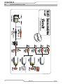
2.04.03 Generator Recommendations
When using generators to power the CM40 Plasma Cutting System, the following ratings are a
minimum and are to be used along with the ratings previously listed.
CM 40 Generator Specications
Generator Output Rating CM 40 Output Current Arc Characteristic
3 kW / 120V 20A on 15A circuit Full
5 kW / 120V 27A on 20A circuit Full
6.8 kW 40A Full
NOTE: If Generator is equipped with an idle mode it will need to be in "Run" mode to operate at 40 amps.
NOTE!
Due to circuitry, age and condition two generators with the same ratings may produce dierent results. Adjust the
amperage accordingly.
2.05 Input Wiring Specications
1 Phase Input Cable Wiring Requirements
1 Phase CutMaster 40 Power Supply Input Cable Wiring Requirements
Input voltage Freq Power Input Suggested Sizes
Volts Hz kVA I max I
1
e
Fuse
(amps)
Flexible Cord
(Min. AWG)
1 Phase
120 / 15A 50/60 2.3 19.3 13.6 15 12 AWG (4mm
)
120 / 20A 50/60 3.1 25.3 18.3 20 12 AWG (4mm
)
208 50/60 6.1 29.2 18.5 50 12 AWG (4mm
)
220 50/60 6.1 27.9 17.6 50 12 AWG (4mm
)
230 50/60 6.0 26.1 16.5 50 12 AWG (4mm
)
240 50/60 6.0 25.1 15.9 50 12 AWG (4mm
)
Line Voltages with Suggested Circuit Protection and Wire Sizes
Based on National Electric Code and Canadian Electric Code
NOTE!
Refer to Local and National Codes or local authority having jurisdiction for proper wiring requirements.
Cable size is de-rated based on the Duty Cycle of the equipment.
Art# A-14359

CUTMASTER 40
INTRODUCTION 0-5557
16
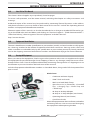
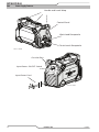
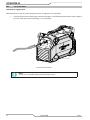
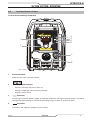
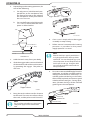
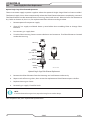
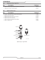
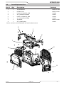
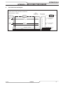
2.06 Power Supply Features
Handle and Leads Wrap
Torch Leads Receptacle
Control Panel
Work Lead Receptacle
Art # A-14041
Input Power Cord
Gas Inlet Port
Input Power ON/OFF Switch
Art # A-14042

CUTMASTER 40
0-5557 INTRODUCTION
17
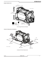
Weights and Dimensions
18.82"
478.07 mm
29 lb / 13.154 kg
8”
203.29 mm
12.25"
311.21 mm
Art # A-14039
Power Supply Dimensions & Weight
Clearances for Operation and Ventilation
15"
381 mm
6"
150 mm
15"
381 mm
6"
150 mm
Art # A-14040
Ventilation Clearance Requirements

CUTMASTER 40
INTRODUCTION 0-5557
18
This Page Intentionally Blank

CUTMASTER 40
0-5557 INTRODUCTION
19
SECTION 2 TORCH: INTRODUCTION
2T.01 Scope of Manual
This manual contains descriptions, operating
instructions and maintenance procedures for the
1Torch Model SL60™ Plasma Cutting Torch. Service
of this equipment is restricted to properly trained
personnel; unqualied personnel are strictly cau-
tioned against attempting repairs or adjustments
not covered in this manual, at the risk of voiding
the Warranty.
Read this manual thoroughly. A complete under-
standing of the characteristics and capabilities
of this equipment will assure the dependable
operation for which it was designed.
2T.02 General Description
!!
CAUTION
Torch Leads are exible but internal wires can
be broken. Do not exceed a 2" radius bend and
avoid repeated tight bends when possible.
Refer to the Appendix Pages for
additional specications as related
to the Power Supply used.
2T.03 Specications
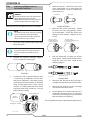
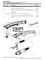
A. Torch Congurations
1. Hand/Manual Torch, Models
The hand torch head is at 75° to the torch
handle. The hand torches include a torch
handle and torch trigger assembly.
10.125" (257 mm)
3.75"
(95 mm)
1.17" (29 mm)
Art # A-03322_AB
Hand Torches are available as follows:
• 20 ft / 6.1 m
• 50 ft / 15.2 m
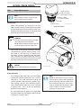
C. Torch Parts
Starter Cartridge, Electrode, Tip, Shield Cup
D. Parts - In - Place (PIP)
Torch Head has built - in switch
15 VDC circuit rating
E. Type Cooling
Combination of ambient air and gas stream
through torch.
F. Torch Ratings
Manual Torch Ratings
Ambient
Temperature
104° F
40° C
Duty Cycle
100% @ 60 Amps @ 400
scfh
Maximum
Current
60 Amps
Voltage (V
peak
) 500V
Arc Striking
Voltage
500V
G. Gas Requirements
Manual Torch Gas Specifications
Gas (Plasma and Secondary) Compressed Air
Operating Pressure
Refer to NOTE
90 - 120 psi
6.2 - 8.3 bar
Maximum Input Pressure 125 psi / 8.6 bar
Gas Flow (Cutting and
Gouging)
5 - 8.3 SCFM
300 - 500 scfh
142 - 235 lpm
!!
WARNING
This Torch is not to be used with oxygen (O
2
).
The SL60QD torch should not be used on an HF
system.
NOTE!
Operating pressure varies with torch model,
operating amperage, and torch leads length. Refer
to gas pressure settings charts for each model.
H. Direct Contact Hazard
For stando tip the recommended stando
is 3/16 inches / 4.7 mm.

CUTMASTER 40
INTRODUCTION 0-5557
20
This Page Intentionally Blank
La page est en cours de chargement...
La page est en cours de chargement...
La page est en cours de chargement...
La page est en cours de chargement...
La page est en cours de chargement...
La page est en cours de chargement...
La page est en cours de chargement...
La page est en cours de chargement...
La page est en cours de chargement...
La page est en cours de chargement...
La page est en cours de chargement...
La page est en cours de chargement...
La page est en cours de chargement...
La page est en cours de chargement...
La page est en cours de chargement...
La page est en cours de chargement...
La page est en cours de chargement...
La page est en cours de chargement...
La page est en cours de chargement...
La page est en cours de chargement...
La page est en cours de chargement...
La page est en cours de chargement...
La page est en cours de chargement...
La page est en cours de chargement...
La page est en cours de chargement...
La page est en cours de chargement...
La page est en cours de chargement...
La page est en cours de chargement...
La page est en cours de chargement...
La page est en cours de chargement...
La page est en cours de chargement...
La page est en cours de chargement...
La page est en cours de chargement...
La page est en cours de chargement...
La page est en cours de chargement...
La page est en cours de chargement...
La page est en cours de chargement...
La page est en cours de chargement...
La page est en cours de chargement...
La page est en cours de chargement...
-
 1
1
-
 2
2
-
 3
3
-
 4
4
-
 5
5
-
 6
6
-
 7
7
-
 8
8
-
 9
9
-
 10
10
-
 11
11
-
 12
12
-
 13
13
-
 14
14
-
 15
15
-
 16
16
-
 17
17
-
 18
18
-
 19
19
-
 20
20
-
 21
21
-
 22
22
-
 23
23
-
 24
24
-
 25
25
-
 26
26
-
 27
27
-
 28
28
-
 29
29
-
 30
30
-
 31
31
-
 32
32
-
 33
33
-
 34
34
-
 35
35
-
 36
36
-
 37
37
-
 38
38
-
 39
39
-
 40
40
-
 41
41
-
 42
42
-
 43
43
-
 44
44
-
 45
45
-
 46
46
-
 47
47
-
 48
48
-
 49
49
-
 50
50
-
 51
51
-
 52
52
-
 53
53
-
 54
54
-
 55
55
-
 56
56
-
 57
57
-
 58
58
-
 59
59
-
 60
60


ESAB CUTMASTER 40 PLASMA CUTTING SYSTEM Manuel utilisateur
- Taper
- Manuel utilisateur
- Ce manuel convient également à
dans d''autres langues
Documents connexes
-
ESAB Thermal Dynamics, Cut40 Le manuel du propriétaire
-
-
ESAB CUTMASTER 40 PLASMA CUTTING SYSTEM Manuel utilisateur
-
 Thermal Dynamics 38 CUTMASTER™ Plasma Cutting System Manuel utilisateur
-
 Thermal Dynamics Cutmaster 60I PLASMA CUTTING SYSTEM Manuel utilisateur
-
 Firepower Plasma Cutting Power Supply Firepower™ PC-800 Manuel utilisateur
-
 Thermal Dynamics PakMaster™ 100 XL™ Plus Air Plasma Cutting Power Supply Manuel utilisateur
-
 Firepower Plasma Cutting Power Supply Firepower PC-500 Manuel utilisateur
-
 Thermal Dynamics PakMaster™ 100 XL™ Plus Air Plasma Cutting Power Supply Manuel utilisateur
-
 Thermal Dynamics PakMaster™ 75 XL™ Plus Air Plasma Cutting Power Supply Manuel utilisateur


