
For NX64 models: 6 cu.ft., R.V. refrigerators.
For NX64IM models: 6 cu.ft., R.V. refrigerators with ice maker.
For NX84 models: 8 cu.ft., R.V. refrigerators.
For NX84IM models: 8 cu.ft., R.V. refrigerators with ice maker.
The model numbers of 3-way refrigerators include “.3”. The model numbers of 2-way
refrigerators do not.
NORCOLD, Inc.
P.O. Box 4248
Sidney, OH 45365-4248
Part No. 636000E (9/28/2015)
English
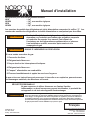
Installation Manual
Improper installation, adjustment, alteration, service or maintenance can
cause injury or property damage. Refer to this manual. For assistance
or additional information, contact a qualied installer, service agency, or
the gas supplier.
FIRE OR EXPLOSION HAZARD
If you smell gas:
1. Open Windows
2. Do not attempt to light appliance.
3. Do not touch electrical switches.
4. Extinguish any open ame
5. Shut off fuel supply.
6. Evacuate immediately and call emergency services.
Failure to follow these instructions could result in re or explosion, which could cause
property damage, personal injury, or death.
DO NOT install this refrigerator in below deck marine applications. Do not install this refrigerator in a
xed indoor cabin or other dwelling applications. This refrigerator must use only NORCOLD designed and
approved outside air intake and exhaust ventilation for correct and safe operation. Any other ventilation
could cause lethal combustion exhaust fumes and/or explosive propane gas fumes to be in the living area
and/or to be below deck.
FOR YOUR SAFETY
Do not store or use gasoline or other ammable vapors and liquid in the
vicinity of this or any other appliance.
WARNING
!
WARNING
!
WARNING
!
Norcold Customer Support Dept.
Telephone: 800-543-1219
Fax: 734-769-2332
Web Site: www.norcold.com

Installation Manual 2
Table of Contents
Safety Awareness
Safety Instructions
Safety Awareness ..................................................................................................................................................................................... 2
Safety Instructions ....................................................................................................................................................................................2
Certication and Code Requirements.......................................................................................................................................................3
Ventilation Requirements..........................................................................................................................................................................4
Key Refrigerator Dimensions....................................................................................................................................................................5
Assemble the Enclosure for the Refrigerator............................................................................................................................................5
Install the Lower and Upper Vents............................................................................................................................................................6
Install the Decorative Door Panels .........................................................................................................................................................10
Install the Refrigerator ............................................................................................................................................................................ 11
Reverse the Door Swing (optional).........................................................................................................................................................12
Connect the Ice Maker (NX6IM and NX8IM models) .............................................................................................................................15
Connect the water supply line .........................................................................................................................................................15
Connect the Electrical Components .......................................................................................................................................................16
Connect the 120 volts AC supply ....................................................................................................................................................16
Connect the 12 volts DC supply ......................................................................................................................................................16
Connect the Low Ambient Heater (optional) ...........................................................................................................................................17
Connect the Propane Gas Components.................................................................................................................................................18
Connect the propane gas supply system ........................................................................................................................................18
Examine the gas supply system for leaks .......................................................................................................................................18
Ignition and Start Up ............................................................................................................................................................................... 19
Ignition and start up ......................................................................................................................................................................... 19
Modes of operation..........................................................................................................................................................................21
Do a test of the gas safety valve .....................................................................................................................................................21
Shut down-all models ......................................................................................................................................................................21
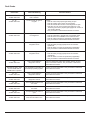
Fault Codes ............................................................................................................................................................................................22
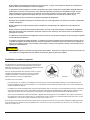
Read this manual carefully and understand the contents before you install the refrigerator.
Be aware of possible safety hazards when you see the safety alert symbol on the refrigerator and in this manual. A signal word follows
the safety alert symbol and identies the danger of the hazard. Carefully read the descriptions of these signal words to fully know their
meanings. They are for your safety.
This signal word means a hazard, which if ignored, can cause dangerous personal injury, death, or much
property damage.
This signal word means a hazard, which if ignored, can cause small personal injury or much property
damage.
- This refrigerator is not approved for use as a free standing refrigerator. It is equipped for the use of propane gas only
and can not be changed to use any other fuels (natural gas, butane, etc.).
- Incorrect installation, adjustment, alteration, or maintenance of this refrigerator can cause personal injury, property
damage, or both.
CAUTION
!
WARNING
!
WARNING
!

Installation Manual 3
- Obey the instructions in this manual to install intake and exhaust vents.
- Do not install the refrigerator directly on carpet. Put the refrigerator on a metal or wood panel that extends the full
width and depth of the refrigerator.
- Do not allow anything to touch the refrigerator cooling system.
- Propane gas can ignite and cause an explosion that can result in property damage, personal injury, or death. Do not
smoke or create sparks. Do not use an open ame to examine the propane gas supply line for leaks. Always use two
wrenches to tighten or loosen the propane gas supply line connections.
- Make sure the electrical installation obeys all applicable codes. See “Certication and Code Requirements” section.
- Do not bypass or change the refrigerator’s electrical components or features.
- Do not spray liquids near electrical outlets, connections, or the refrigerator components. Many liquids are electrically
conductive and can cause a shock hazard, electrical shorts, and in some cases re.
- The refrigerator cooling system is under pressure. Do not try to repair or to recharge a defective cooling system.
- The cooling system contains sodium chromate. The breathing of certain chromium compounds can cause cancer. The
cooling system contents can cause severe skin and eye burns, and can ignite and burn with an intense ame. Do not
bend, drop, weld, move, drill, puncture, or hit the cooling system.
- The rear of the refrigerator has sharp edges and corners. To prevent cuts or abrasions when working on the
refrigerator, use caution and wear cut resistant gloves.
Certication and Code Requirements
This refrigerator is certied by CSA International as meeting the
latest edition of ANSI Z21.19 / CSA 1.4 standards for installation
in mobile homes or recreational vehicles.
The refrigerator must be installed in accordance with this
“Installation Manual” in order for the Norcold limited warranty
to be in effect. In addition, the installation must conform to the
following, as applicable:
In the United States and Canada:
- Local codes, or in the absence of local codes, the National Fuel Gas Code, ANSI Z223.1/NFPA 54, the Natural Gas and Propane
installation Code, CSA B149.1, ANSI A119.2 Recreational Vehicles Code, and CSA Z240 RV Series, Recreational Vehicles.
- A manufactured home (mobile home) installation must conform with the Manufactured Home Construction and Safety Standard,
Title 24 CFR, Part 3280 [formerly the Federal Standard for Mobile Home Construction and Safety, Title 24 (part 280), and the
current CSA Z240.4, Gas-equipped Recreational Vehicles and Mobile Housing.
- If an external power source is utilized, the appliance, when installed, must be electrically grounded in accordance with local codes
or, in the absence of local codes, the National Electrical code, and ANSI/NFPA 70, or the Canadian Electrical Code, CSA C22.2.
Parts 1 and 2.
All propane gas supply piping and ttings must obey local, state, and national codes about type and size. These components must also
obey the current NFPA 1192 section 2-4, and in Canada with the current CAN 1-6.10 Standard.
Art01290
CAUTION
!

Installation Manual 4
Ventilation Requirements
The completed installation must:
- Make sure there is sufcient intake of fresh air for combustion.
- Make sure the living space is completely isolated from the combustion system of the refrigerator.
- Make sure there is complete and unrestricted ventilation of the ue exhaust which, in gas mode, can produce carbon
monoxide. The breathing of carbon monoxide fumes can cause dizziness, nausea, or in extreme cases, death.
- Make sure the refrigerator is completely isolated from its heat generating components through the correct use of
bafes and panel construction.
Certied installation needs one lower intake vent and one upper exhaust vent. Install the vents exactly as written in this manual. Any
other installation method voids both the certication and the factory warranty of the refrigerator.
The bottom of the opening for the lower intake vent, which is also the service access door, must be even with or immediately below the
oor level. This allows any leaking propane gas to escape to the outside and not to collect at oor level.
CSA International certication allows the refrigerator to have zero (0) inch minimum clearance at the sides, rear, top, and bottom. While
there are no maximum clearances specied for certication, the following maximum clearances are necessary for correct refrigerator
performance:
Bottom 0 inch min. 0 inch max.
Each Side 0 inch min 1/2 inch max.
Top 0 inch min. 1/4 inch max.
Rear 0 inch min. 1 inch max.
These clearances plus the lower and upper vents cause the natural air draft that is necessary for good refrigeration. Cooler air comes
in through the lower vent, goes up around the refrigerator coils where it removes the excess heat from the refrigerator components, and
goes out through the upper vent. If this air ow is blocked or decreased, the refrigerator will not cool correctly.
Each NORCOLD model is certied by CSA International for correct ventilation. Install only the certied vents that are listed in this
manual.
WARNING
!

Installation Manual 5
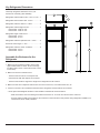
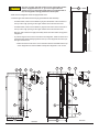
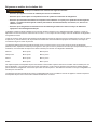
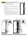
Key Refrigerator Dimensions
These key refrigerator dimensions are for your
reference as necessary (See Art02384).
Refrigerator cabinet width w/o trim - 23.47 in. max. ...1
Refrigerator width overall w/ trim - 24.6 in. ................. 2
Refrigerator cabinet to side trim - 0.80 in. ..................3
Refrigerator cabinet height w/o trim............................4
NX6 models - 52.85 in. max.
NX8 models - 59.85 in. max.
Refrigerator height overall w/ trim...............................5
NX6 models - 54.5 in.
NX8 models - 61.5 in.
Refrigerator cabinet to top/bottom trim - 0.93 in. ........ 6
Enclosure wall to hinges - 1.22 in. ..............................7
Refrigerator cabinet to center of handles ...................8
NX6 models - 32.5 in.
NX8 models - 39.5 in.
8
3
5
6
7
1
2
4
Art02384
1. Make sure the enclosure is 59.88 - 60.01 inches
high for NX8 models or 52.88 - 53.01 inches high
for NX6 models x 23.50 - 23.63 inches wide x 24.00
inches deep.
2. Make sure the oor is solid and level.
- The oor must be metal or a wood panel and
extend the full width and depth of the enclosure.
- The oor must be able to support the weight of the refrigerator and its contents.
3. Make sure there are no adjacent heat sources such as a furnace vent, a hot water heater vent, etc.
4. If there is more than 1/2 inch between either side of the refrigerator and the inside of the enclosure:
- Fill the space with berglass insulation or add a bafe to eliminate the excess clearance.
- Make sure that the rear of the batt-type insulation is between 18 - 19 inches from the face of the enclosure.
- Securely attach the batt-type insulation to the enclosure so that it remains in this position during refrigerator installation, if it
becomes wet, and in windy conditions.
Assemble the Enclosure for the
Refrigerator

Installation Manual 6
Install the Lower and Upper Vents
1. Using the following chart, decide which vents and rough opening (RO) sizes to use:
Certied Vent P/N RO Height RO Width
Upper Roof Exhaust Cap 622293 N/A N/A
Upper Roof Exhaust Vent 616319 24 in. 5 1/4 in.
Upper Exhaust & Lower Intake - Plastic 621156 13 3/4 in. 21 1/2 in.
Lower Square Corner Intake 616010 9 3/4 in. 19 3/8 in.
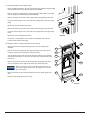
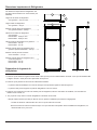
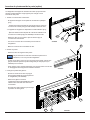
2. Install the lower intake vent (See Art01598, Art01599, and Art01602):
The lower intake vent is also the service access opening for the
components on the rear of the refrigerator.
Make sure the bottom of the opening of the lower intake vent is
even with or immediately below the oor level. This allows any
leaking propane gas to escape to the outside and not to collect at
oor level.
- Make sure the bottom of the opening of the lower intake vent [9] is even with or
immediately below the oor level.
- Align the lower intake vent vertically below the coils [10] and the condenser [11] of the
refrigerator.
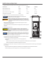
3. Install the upper exhaust vent:
Make sure that no sawdust, insulation, or other construction
debris is on the refrigerator or in the enclosure. Debris can cause
a combustion hazard and prevent the refrigerator from operating
correctly.
Tighten the screws of the upper roof exhaust cap to 10 inch-pounds max.
Also make sure that the air ow around the upper roof exhaust cap is not
blocked or decreased by other roof mounted features such as a luggage
carrier, an air conditioner, a solar panel, etc.
- If the design of the vehicle allows, install the roof exhaust vent [12] directly above the
condenser [11] of the refrigerator (See Art01598):
- Install a bafe [13] to prevent stagnant hot air in the area [14] above the
refrigerator.
- Make sure there is less than 1/4 inch clearance [15] between the bafe and the top of the refrigerator.
- Make sure the bafe is the full width of the inside of the enclosure.
- If the design of the vehicle does not allow you to install the roof exhaust vent directly above the condenser [11] of the refrigerator
(See Art01599):
- Align the roof exhaust vent [12] above the condenser [11] of the refrigerator and move it inboard as necessary.
- Install two bafes [13] to prevent stagnant hot air in the area [14] above the refrigerator.
10
11
9
Art01602
CAUTION
!
NOTICE
NOTICE
WARNING
!

Installation Manual 7
- Make sure the bafes are the full width of the inside of the enclosure.
- Make sure that the bafes are no more than 45° from vertical [20].
- Put one bafe between the top rear edge of the refrigerator and the inside edge of the upper exhaust vent opening.
- Put the other bafe between the outside edge of the upper exhaust vent opening and the side wall of the vehicle.
- If the depth of the enclosure is 24 inches or more and is less than 25 inches, no bafes are necessary at the rear of the enclosure.
- If the depth of the enclosure is 25 inches or more and is less than 26 inches, add two bafes [16] to the rear of the enclosure (See
Art01598 and Art01599).
- Put one bafe 18 inches to 18 1/2 inches above the bottom of the enclosure [17] (4 1/4 inches to 4 3/4 inches above the top of
the lower intake vent opening REF) [18] .
- Put the other bafe at the lowest edge of the condenser [11] of the refrigerator.
- Make sure that the bafes are 1 inch or less [19] from the coils [10] and condenser of the refrigerator.
- Make sure that the bafes are the full width of the inside of the enclosure.
Art01598
14
9
11
12
13
15
16
10
17
18
15
15
16
Art01599
20
14
13
12
11
16
9
10
18
17
19
16
19

Installation Manual 8
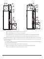
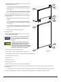
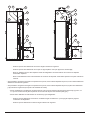
- If the depth of the enclosure is more than 26 inches, install a wood or an aluminum or galvanized sheet solid box bafe [21] in the
rear of the enclosure (See Art01617 and Art01618).
- Make sure that the bottom of the solid box bafe is 18 inches to 18 1/2 inches above the bottom of the enclosure [17] (4 1/4
inches to 4 3/4 inches above the top of the lower intake vent opening REF) [18].
- Make sure that the back of the solid box bafe is perpendicular to the bottom of the enclosure.
- Make sure that the back of the solid box bafe is either against the top of the enclosure or against the angled bafe [13]
(depending on the vehicle design).
- Make sure that the solid box bafe is one inch or less [19] from the coils [10] and condenser of the refrigerator.
- Make sure that the solid box bafe is the full width of the inside of the enclosure.
- If the design of the vehicle does not allow you to install a roof exhaust vent, install an upper side-wall exhaust vent.
The refrigerator is 23.7 in. min. to 24.0 in. max. from the rear of the breaker to the rear of the condenser [22].
NX6 models are 47.1 in. min. to 47.4 in. max. from the bottom of the refrigerator to the bottom of the refrigerator
condenser [23].
NX8 models are 54.1 in. min. to 54.4 in. max. from the bottom of the refrigerator to the bottom of the refrigerator
condenser [23] (See Art01601).
Art01617
14
15
13
12
19
11
21
18
17
10
9
Art01618
14
20
12
13
11
19
21
18
17
10
9
NOTICE

Installation Manual 9
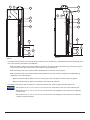
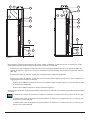
Only use an upper side-wall exhaust vent on refrigerator models
that are equipped with a fan. If you use an upper side-wall
exhaust vent on a refrigerator model that is not equipped with a
fan, the refrigerator cooling performance will be poor.
- Make sure the refrigerator model is equipped with a fan.
- Install the upper side-wall exhaust vent [24] (See Art01592 and Art01593).
- For NX6 models, make sure the distance [25] from the bottom of the enclosure to
the top of the rough opening for the upper exhaust vent is at least 55 inches.
- For NX8 models, make sure the distance [25] from the bottom of the enclosure to
the top of the rough opening for the upper exhaust vent is at least 62 inches.
- Align the upper exhaust vent [24] horizontally above the lower intake vent [9] of the
refrigerator.
- To prevent stagnant hot air in the area above the refrigerator, install an aluminum or
galvanized steel sheet bafe [13] between the top of the refrigerator and the top of
the upper exhaust vent.
- Make sure there is less than 1/4 inch clearance between the bafe and the top
of the refrigerator and that the bafe overlaps the refrigerator 1 inch or less.
22
23
Art01601
Art01592
16
15
17
17
213
21
14
13
19
1
2
18
Art01593
27
17
10
9
18
25
21
24
1513
15
11
15
213
CAUTION
!

Installation Manual 10
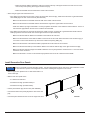
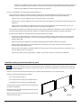
The doors are made to accept decorative panels. The decorative panels must be 3/16 inch or less in thickness. Install
the decorative door panels in the refrigerator doors before installing the refrigerator in the vehicle.
- Make an upper door panel that is 21 19/32 inches wide x 15
11/16 inches high.
- Make a lower door panel that is:
- 21 19/32 inches wide and
- 32 25/32 inches high (for NX6 models) or
- 39 25/32 inches high (for NX8 models).
- Pull the panel retainer [37] off each door (See Art02385).
- Push the decorative door panel [38] into the slots of the door
[39].
- Push each panel retainer into the slot on the edge of the door.
Install Decorative Door Panels
- Make sure that the bafe is against the wall of the vehicle at the top of the upper exhaust vent and 1/4 inch or less
from the top of the opening for the upper exhaust vent [15].
- Make sure the bafe is the full width of the inside of the enclosure.
- When using an upper side-wall exhaust vent:
- If the depth of the enclosure is 24 inches or more and is less than 26 inches [27], install a bent aluminum or galvanized steel
sheet bafe [26] to the rear of the enclosure (See Art01592).
- Make sure that the bend of the bafe is the full width of the inside of the enclosure.
- Make sure that the bend of the bafe is ush with the bottom edge of the upper intake vent door frame.
- Make sure that the top edge of the bafe is 1/4 inch [213] below the bottom of the condenser and that there is 1/4 inch or
less clearance [15] between the rear of the condenser and the bafe.
- If the depth of the enclosure is more than 26 inches [27], install a wood or an aluminum or galvanized steel sheet solid box
bafe [21] between the lower intake vent and the upper exhaust vent (See Art01593).
- Make sure that the solid box bafe is the full width of the inside of the enclosure.
- Make sure that the bottom of the solid box bafe is 18 inches to 18 1/2 inches above the bottom of the enclosure [17] (4
1/4 inches to 4 3/4 inches above the top of the lower intake vent opening REF) [18] .
- Make sure that the back of the solid box bafe is perpendicular to the bottom of the enclosure.
- Make sure that the horizontal top of the solid box bafe is even with the bottom edge of the upper exhaust vent [24].
- Make sure that the vertical top edge of the bafe is between 1/4 inch [213] below the condenser and 1 1/2 inches above
the bottom of the condenser.
- Make sure that there is 1/4 inch or less clearance [15] between the rear of the condenser and the bafe.
Art02385
37
38
39
NOTICE

Installation Manual 11
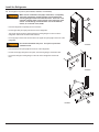
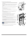
Put the refrigerator in position (See Art00962, Art00963, and Art00964):
Make sure the combustion seal [28] is not broken, is completely
around the refrigerator mounting anges, and is between the
mounting anges and the wall of the enclosure If the seal is not
complete, exhaust fumes can be present in the living area of the
vehicle. The breathing of exhaust fumes can cause dizziness,
nausea, or in extreme cases, death.
- Push the refrigerator completely into the enclosure.
- Put the upper trim piece [40] onto the front of the refrigerator.
- Put screws [41] through the upper and lower mounting anges on the front of the
refrigerator and into the enclosure wall and oor.
- Put a cap [42] on each of the screw holes in the upper trim piece [40] on the front of the
refrigerator.
Do not omit the bottom trim piece. This piece is part of the
combustion seal.
- Push the bottom trim piece [29] onto the front of the refrigerator.
- Put two screws [41] through the trim piece, the mounting ange, and into the oor.
- Put screws through mounting ange on the rear of the refrigerator and into the
oor.
Install the Refrigerator
Art00962
28
29
Art00963
41
42
40
Art00964
41
29
41
WARNING
!
WARNING
!

Installation Manual 12
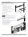
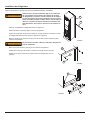
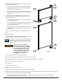
Reverse the Door Swing (optional)
This refrigerator has cabinet hinges that allow you to change the
direction the door opens by moving the hinges on a diagonal to the
opposite side.
1. Remove the control cover:
- If the unit is equipped with a plastic control facade [271];
- Carefully pull the snap-on control facade off of the control
cover[270] (See ART 02386) and set aside.
- If the unit is equipped with an adhesive control label [271];
- Carefully peel the adhesive control label off the control cover [270]
(See Art02386) and set aside.
- Remove the two outermost screws [41] from the control cover.
- Pull the control cover away from the refrigerator.
- Set the control cover aside.
2. Remove the doors:
- Remove the storage bins from the doors.
Do not mix the upper and lower hinge pins because they are
different.
- Using either a 7/16” wrench or a straight screwdriver, remove and save the
upper (hex-head) hinge pin [63] from each door (See Art02387).
- Open each door, tilt it slightly forward, and pull it up and off of the bottom
hinge bushing.
3. Change the position of the strike plates:
- Remove and save the two screws [41] that attach the strike plate [65A] for
the upper door to the refrigerator (See Art02388).
- turn the strike plate over and attach it in the
location for the strike plate [65B] of the lower
door on the other side of the control area.
- Use the same procedure to change the
position of the other strike plate.
Art02386
270
271
41
Art02387
63
Art02388
65A
65B
41
NOTICE

Installation Manual 13
4. Change the position of the cabinet hinges:
- Using a straight screwdriver, remove and save the lower (straight) hinge pins [64]
from each both of the lower cabinet hinges (See Art02389).
- Remove the two L-shaped plastic covers [273] and the black plastic cover [305]
that are opposite the cabinet hinges (See Art02390).
- Remove and save the screws from the upper cabinet hinge [66a] of each door.
- Put each of these hinges on the other side of the refrigerator as the lower hinge
[66b].
- Attach each of these hinges with screws.
- Remove and save the screws from the lower cabinet hinge [67a] of each door.
- Put each of these hinges on the other side of the refrigerator as the upper hinge
[67b].
- Attach each of these hinges with screws.
- Put the two L-shaped plastic covers and the black plastic cover over the
holes that were used by the hinges.
5. Change the position of the door handles and door hinges:
- Remove and save the hinge bushings [74] from each door hinge (See
Art02391.
- Remove the screws and the at door hinge [274a] from each door (on the
top of the upper door and the bottom of the lower door).
- Turn the at door hinge over and use the screws to attach it to the opposite
side [274b] of each door (on the top of the upper door and the bottom of the
lower door).
- Remove and save the screws and the shaped door hinge [275] from each
door (on the bottom of the upper door and the top of the lower door).
When you remove each door handle [70] from the door, the
latch and the spring will be loose. Be careful not to lose the
latch or the spring.
- Remove and save the two screws that attach each door handle [70a] to the
door.
- Pull each door handle away from the door.
Art02389
64
Art02390
66a
67b
67a
66b
273
66a
67a
67b
66b
273
305
NOTICE

Installation Manual 14
- Turn each bent hinge over and attach it, with the screws, to the
opposite side of the other door.
- If you removed the bent hinge [275a] from the left side of
upper door, attach the bent hinge [275b] to the right side of
the lower door.
- If you removed the bent hinge from the right side of upper
door, attach the bent hinge to the left side of the lower door.
- With the handle latches and springs in place, turn each door
handle over and attach it, with the screws, to the opposite side
of the other door.
- Make sure that the latch and the spring are in each door
handle.
- If you removed the door handle [70a] from the left side of
upper door, attach the door handle [70b] to the right side of
the lower door.
- If you removed the door handle from the right side of upper
door, attach the door handle to the left side of the lower
door.
- Put a hinge bushing back into each door hinge.
4. Reinstall the doors:
- Turn the lower (straight) hinge pin [64] into each of the lower
cabinet hinges (See Art02389).
To prevent damage to the threads of the hinge
pins, turn the hinge pins by hand until tight
and then tighten with a 7/16 inch wrench or a
screwdriver.
Apply Loctite removable thread locker
(blue) to the threads of the hinge screws
before assembly to prevent loosening
during use. Do not allow Loctite to contact
any of the plastic surfaces of the refrigerator
because it can damage those surfaces.
- Put each door down onto the lower hinge pin.
- Align the holes in the upper hinges and hold in this position.
- Turn the upper hinge pin [63] into the hinges of each door (See Art02387).
- Put the storage bins in the doors.
- Close the doors
- Tighten the hinge pins.
5. Reinstall the control cover:
- Using screws, attach the control cover [270] to the refrigerator.
- If the unit is equipped with a plastic control facade, carefully push the snap-on control facade [271] onto the control cover
(See Art02386).
- You may hear a “click’ sound or feel a “snap” in your ngers when the control facade fully engages into the control cover.
- If the unit is equipped with an adhesive control label, align the label with the conrol buttons and press into place.
Art02391
274a
70a
74
74
74
274b
274a
274b
275a
275b
70b
NOTICE
CAUTION
!

Installation Manual 15
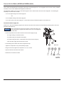
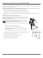
Connect the Ice Maker (NX6IM and NX8IM models)
The ice maker is assembled to the refrigerator at the factory as optional equipment. If the refrigerator does not have a factory installed
ice maker, one can not be added to the refrigerator at a later time.
The refrigerator installer must connect a cold water supply line to the solenoid valve at the rear of the refrigerator. The following are
necessary to connect to the ice maker:
- 1/4 in. OD copper tubing for the water supply line.
OR
- 1/4 in. OD plastic tubing for the water supply line.
- 1/4 in. shut off valve in the water supply line. This should be easily accessible through the lower intake vent.
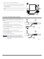
Connect the water supply line:
Install a 1/4 in. OD water supply line [43] from the water shut off valve of the vehicle to the solenoid water valve [44] at the rear of the
refrigerator (See Art01014):
A brass compression nut [45], a brass sleeve, a plastic sleeve [46] , and
a brass insert [47] are supplied and attached to the rear of the refrigerator
(See Art01755).
- Put the compression nut and then the sleeve onto the water supply line [43].
- For copper tubing, use the brass sleeve.
- For plastic tubing, use the plastic sleeve [46].
- For plastic tubing with .040 in. wall thickness, also use the brass insert [47].
- Flush the water supply line until the water is clear.
- Put the tubing into the water valve until it is against the stop.
- Tighten the compression nut by hand (hard nger tight).
- Using two wrenches, tighten the compression nut 1 ½ to 2 turns.
- Open the water shut off valve of the vehicle.
- Examine the connections for leaks.
43
44
45
48
Art01014
NOTICE

Installation Manual 16
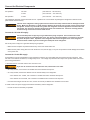
Connect the Electrical Components
AC Operation 120 volts (132 volts max. - 108 volts min.)
12 volts (15.4 volts max. - 10.5 volts min.)
DC Operation 12 volts (15.4 volts max. - 10.5 volts min.)
This refrigerator operates on these electrical sources. Operation out of these limits may damage the refrigerator’s electrical circuit
parts and will void the warranty.
The rear of the refrigerator cooling system has hot surfaces and sharp surfaces that can damage electrical
wiring. Make sure that there is a good clearance between all electrical wiring and the cooling system of the
refrigerator. Position any electrical wiring within the refrigerator enclosure opposite the burner side of the
refrigerator. Do not put any electrical wiring through the roof exhaust vent. Failure to correctly position
electrical wiring can result in electrical shock or re.
Connect the 120 volts AC supply:
Connect the AC power cord(s) only to a grounded three-prong receptacle. Do not remove the round
ground prong from any of the AC power cords. Do not use a two prong adapter or an extension cord with
any of the AC power cords. Operation of the refrigerator without correct ground can cause dangerous
electrical shock or death if you are touching the metal parts of the refrigerator.
Put the AC power cord(s) into a grounded three-prong receptacle:
- Make sure the receptacle is positioned within easy reach of the lower intake vent.
- Make sure the power cord(s) does not touch the burner cover, the ue pipe, or any hot component that could damage the insulation
of the power cord.
Connect the 12 volts DC supply:
As the distance from the vehicle battery to the refrigerator increases, the correct AWG wire size and fuse size also increases. If the
wire size is too small for the distance, a voltage drop occurs. The voltage drop decreases the output of the system heater and causes
poor cooling performance.
1. Determine the min. wire size and the max. fuse size to use:
If you use an incorrect wire size and/or fuse size, electrical re can result.
- On 2-way models, use a minimum of 18 AWG wire and a maximum 6 Amp fuse.
- On 3-way models, measure the distance from the vehicle battery to the refrigerator.
- If the distance is 0 - 20 feet, use a minimum of 10 AWG wire and a maximum 30 Amp fuse.
- If the distance is over 20 feet, use a minimum of 8 AWG wire and a maximum 40 Amp fuse.
- If the wire size is larger than the min. size, use the correct fuse per RVIA A119.2 standard or local codes.
2. Install a fuse in DC power supply wires between the battery and the refrigerator:
- Put fuse as close to the battery as possible.
WARNING
!
WARNING
!
WARNING
!

Installation Manual 17
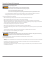
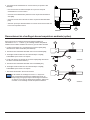
3. Connect the DC power supply wires (See Art02402:
- Attach a 1/4 inch Quick Connect terminal to each DC power supply wire.
- Push the positive DC power wire onto the power board terminal that is
marked 12VDC [288].
- Push the DC ground wire onto the power board terminal that is marked GND
[287].
- Make sure each DC power supply wire is on the correct polarity terminal.
Connect the Low Ambient Heater (optional)
Connect the low ambient heater wires to the 12 volts DC supply. The
black (+) wire of the low ambient heater is 16 AWG and the brown (-) wire
is 18 AWG.
1. Cut the 12V input (+) wire behind the quick connect [269]; strip both
ends (See Art02316).
2. Solder both stripped ends with the 16AWG black wire [266].
3. Wrap the soldered wires with black electrical tape [268]; BE SURE
there are no exposed strands.
4. Cut the 12V ground wire behind the quick connect [269]; strip both
ends (See Art02317).
5. Solder both stripped ends with the 18AWG wire [267].
6. Wrap the soldered wires with black electrical tape [268] ; BE SURE
there are no exposed strands.
7. Connect 12V supply to the input wires.
This kit supplies DC voltage to the heater any time the
ambient temperature is low enough. Extended storage
during cold weather will drain the vehicle batteries. To
prevent battery drain, remove the 3 amp fuse from the low
ambient heater.
Art02402
287
288
Art02316
268
269
266
Art02317
268
269
267
NOTICE

Installation Manual 18
WARNING
!
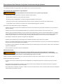
Connect the Propane Gas Components
This refrigerator operates on propane gas at a pressure of 11 inches Water Column Propane.
Connect the propane gas supply system:
Be very careful when working on or near the propane gas system.
- Do not smoke, or use an open ame near the propane gas system.
- Do not use an open ame to examine for leaks.
- Do not connect the refrigerator to the propane gas tank without a pressure regulator between them.
- To avoid a propane gas leak, always use two wrenches to tighten or loosen the propane gas supply line connections.
- Leaking propane gas leak can ignite or explode and result in dangerous personal injury or death.
Connect the gas supply line to the refrigerator:
- Make sure that all tubing and ttings obey all local, state, and national codes about size and type.
- Make sure that all exible metal connectors obey the current CAN1-6.10 Standard.
- Make sure that the materials used for the gas supply line obey both the current ANSI A 119.2 (NFPA 1192) and CSA Z240
Standards on Recreational Vehicles. Norcold recommends the use of 3/8 inch copper tubing as the gas supply line and requires a
3/8 inch SAE (UNF 5/8-18) male are tting as the connection to the refrigerator.
- Put the propane gas supply line up through the oor of the enclosure.
- Make sure the hole through the oor is large enough allow clearance for the gas supply line.
- Put a weather resistant seal (grommet, sealant, etc.) around the gas supply line where it goes through the oor to prevent vibration
and abrasion.
- To prevent vibration and abrasion, make sure that the gas supply line is not against anything in the enclosure.
- Attach the gas supply line to the bulkhead tting of the refrigerator.
Examine the gas supply system for leaks:
Do not allow the leak detecting solution to touch the electrical components. Many liquids are electrically
conductive and can cause electrical shorts and in some cases, re.
Use a leak detecting solution to examine the gas supply line and all propane gas connections for leaks.
If you use compressed air for the test:
- The pressure of the compressed air at the manual shut off valve of the refrigerator must not be more than 1/2 psig (14 inches Water
Column).
- If the pressure of the compressed air is more than 1/2 psig (14 inches Water Column), remove the gas supply line from the
bulkhead tting of the refrigerator before the test.
- If the pressure of the compressed air is equal to or less than 1/2 psig (14 inches Water Column), close the manual shut off valve of
the refrigerator before the test.
WARNING
!

Installation Manual 19
Ignition and Start Up
Before ignition or start up of the refrigerator:
- Make sure the air ow in the lower intake vent, through the refrigerator coils and condenser, and out the upper exhaust vent is not
blocked or decreased.
- Make sure there are no combustible materials in or around the refrigerator.
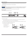
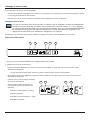
Ignition and start up:
If the gas does not ignite within 30 seconds, the gas valve of the refrigerator will automatically close, the igniter will stop
sparking, an audible alarm will sound, and the fault codes “no” “FL” will ash on the LCD [280]. To reset the controls,
press and hold the POWER ON/OFF button [30] for 1 second to turn the refrigerator off and then press it again to
restart the refrigerator (See Art02397).
If the gas does not ignite after several attempts, refer to the “Fault Codes” section of this manual.
Modes of Operation:
1. Push and release the POWER ON/OFF button [30].
2. Select the mode of operation.
- Push and hold the MODE button [31] to scroll through the available operation modes of the refrigerator, one after the other.
- When the desired mode indicator comes on in the LCD, release the MODE button.
- Or push and release the MODE button again and again to change the available operation modes of the refrigerator, one at a time.
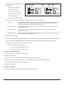
- As you change the mode, the applicable mode indicator will come on.
- On 2-way models, the mode indicators are (See Art02398):
- Auto mode AC electric [281]
- Auto mode gas [282]
- Manual mode AC electric [283]
- Manual mode gas [284]
Art02398
281
282
283
284
NORCOLD
30
280
Art02397
31
32
278
NOTICE

Installation Manual 20
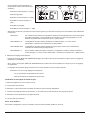
- On 3-way models, the mode indicators are
(See Art02399):
- Auto mode AC electric [281]
- Auto mode gas [282]
- Auto mode DC electric [285]
- Manual mode AC electric [283]
- Manual mode gas [284]
- Manual mode DC electric [286]
- Select one of three (3) modes of operation (four (4) modes of operation on 3-way models only):
AUTO mode The refrigerator’s electronic controls automatically select the the most efcient energy source that
is available. Either the Auto mode AC indicator [281], the Auto mode gas indicator [282], or (on
3-way models only) the Auto mode DC indicator [285] comes on.
MANUAL AC mode The refrigerator cools using only AC electric power as the power source. The Manual mode AC
indicator [283] comes on.
MANUAL GAS mode The refrigerator cools using only propane gas as the power source. The Manual mode gas
indicator [284] comes on.
MANUAL DC mode On 3-way models only, the refrigerator cools using only DC electric power as the power source. The
Manual mode DC indicator [286] comes on.
3. Select the temperature setting:
- Push and hold the TEMPERATURE SET button [32] to scroll through the temperature settings, one after the other (See Art02397).
- Or push and release the TEMPERATURE SET button again and again to change the temperature settings, one at a time.
- The temperature settings [278] come on as numbers in the LCD.
- Select one of nine (9) temperature settings:
- One (1) is the warmest temperature setting.
- Nine (9) is the coldest temperature setting.
Do a test of the gas safety valve:
1. Start up the refrigerator in the manual mode operation.
2. Open the lower intake vent.
3. Remove one wire from the solenoid of the gas safety valve at the rear of the refrigerator.
4. Within 30 seconds, the ame should extinguish. This means that the gas safety valve is operating correctly.
5. Put the wire back on the solenoid of the gas safety valve.
6. Close the lower intake vent.
Shut down - all models:
To shut down the refrigerator, push and hold the ON/OFF button for one second.
Art02399
281
282
285
286
284
283
La page est en cours de chargement...
La page est en cours de chargement...
La page est en cours de chargement...
La page est en cours de chargement...
La page est en cours de chargement...
La page est en cours de chargement...
La page est en cours de chargement...
La page est en cours de chargement...
La page est en cours de chargement...
La page est en cours de chargement...
La page est en cours de chargement...
La page est en cours de chargement...
La page est en cours de chargement...
La page est en cours de chargement...
La page est en cours de chargement...
La page est en cours de chargement...
La page est en cours de chargement...
La page est en cours de chargement...
La page est en cours de chargement...
La page est en cours de chargement...
La page est en cours de chargement...
La page est en cours de chargement...
La page est en cours de chargement...
La page est en cours de chargement...
-
 1
1
-
 2
2
-
 3
3
-
 4
4
-
 5
5
-
 6
6
-
 7
7
-
 8
8
-
 9
9
-
 10
10
-
 11
11
-
 12
12
-
 13
13
-
 14
14
-
 15
15
-
 16
16
-
 17
17
-
 18
18
-
 19
19
-
 20
20
-
 21
21
-
 22
22
-
 23
23
-
 24
24
-
 25
25
-
 26
26
-
 27
27
-
 28
28
-
 29
29
-
 30
30
-
 31
31
-
 32
32
-
 33
33
-
 34
34
-
 35
35
-
 36
36
-
 37
37
-
 38
38
-
 39
39
-
 40
40
-
 41
41
-
 42
42
-
 43
43
-
 44
44


Norcold NXA641/ NX641 Guide d'installation
- Taper
- Guide d'installation
- Ce manuel convient également à
dans d''autres langues
Documents connexes
-
Norcold NX64/NX84 Series Guide d'installation
-
-
-
-
-
-
-
-
Norcold 1210IMBK - Guide d'installation
-