
1
Use, Care, and
Installation Guide
Guide
d’utilisation,
d’entretien et
d’installation
Guía de
instalación, uso y
mantenimiento
READ AND SAVE THESE
INSTRUCTIONS
LISEZ CES
INSTRUCTIONS ET
CONSERVEZ-LES
LEA Y CONSERVE
ESTAS INSTRUCCIONES
LIB0152213
Printed in Mexico
10/18
Models: KIT0154387

2
ENGLISH
Contents
Important safety notice................................................................................................................................................................................................. 3
Installation Requirements ............................................................................................................................................................................................ 4
Tools & Parts ................................................................................................................................................................................................................ 4
Location Requirements ........................................................................................................................................................................................... 5
Product Dimension ................................................................................................................................................................................................... 5
Venting Requirements ............................................................................................................................................................................................. 5
Electrical Requirements .......................................................................................................................................................................................... 6
Installation Instructions ................................................................................................................................................................................................ 6
Prepare the location ................................................................................................................................................................................................ 6
Install In-Blower System .......................................................................................................................................................................................... 9
Make electrical connection for the In-Line Blower System...................................................................................................................... 10
Make electrical between the In-Line Blower System and Range Hood .............................................................................................. 11
Warranty ........................................................................................................................................................................................................................... 14
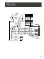
Wiring Diagram .............................................................................................................................................................................................................. 43
APPROVED FOR RESIDENTIAL APPLIANCES
FOR RESIDENTIAL USE ONLY
READ AND SAVE THESE INSTRUCTIONS
PLEASE READ ENTIRE INSTRUCTIONS BEFORE PROCEEDING.
INSTALLATION MUST COMPLY WITH ALL LOCAL CODES.
IMPORTANT: Save these Instructions for the Local Electrical Inspector’s use.
INSTALLER: Please leave these Instructions with this unit for the owner.
OWNER: Please retain these instructions for future reference.
Safety Warning: Turn o power circuit at service panel and lock out panel, before wiring this appliance.
Requirement: 120 V AC, 60 Hz. 15 or 20 A Branch Circuit.

3
I
IMPORTANT SAFETY NOTICE
I CAUTION
FOR GENERAL VENTILATING USE ONLY. DO NOT USE TO
EXHAUST HAZARDOUS OR EXPLOSIVE MATERIALS OR
VAPOURS.
I WARNING
TO REDUCE THE RISK OF FIRE, ELECTRIC SHOCK, OR
INJURY TO PERSONS, OBSERVE THE FOLLOWING:
A. Use this unit only in the manner intended by the
manufacturer. If you have questions, contact the
manufacturer.
B. Before servicing or cleaning the unit, switch power o
at service panel and lock service panel disconnecting
means to prevent power from being switched on
accidentally.
When the service disconnecting means cannot be
locked, securely fasten a prominent warning device,
such as a tag, to the service panel.
C. Installation work and electrical wiring must be done by
qualified person(s) in accordance with all applicable
codes & standards, including fire-rated construction.
D. Sucient air is needed for proper combustion and
exhausting of gases through the flue (Chimney) of fuel
burning equipment to prevent back- drafting.
Follow the heating equipment manufacturers guideline
and safety standards such as those published by the
national fire protection association (NFPA), the american
society for heating, refrigeration and air conditioning
engineers (ASHRAE), and the local code authorities.
E. When cutting or drilling into wall or ceiling, do not
damage electrical wiring and other hidden utilities.
F. Ducted fans must always be vented to the outdoors.
I CAUTION
To reduce risk of fire and to properly exhaust air, be sure to
duct air outside - do not vent exhaust air into spaces within
walls, ceilings, attics, crawl spaces, or garages.
I WARNING
TO REDUCE THE RISK OF FIRE, USE ONLY METAL DUCT
WORK.
Install this accessorry in accordance with all requirements
specified.
I WARNING
To reduce the risk of fire or electric shock, do not use this
hood with any external solid state speed control device.
I WARNING
TO REDUCE THE RISK OF A RANGE TOP GREASE FIRE.
a) Never leave surface units unattended at high settings.
Boilovers cause smoking and greasy spillovers that may
ignite. Heat oils slowly on low or medium settings.
b) Always turn hood ON when cooking at high heat or when
flambeing food (I.e. Crepes Suzette, Cherries Jubilee,
Peppercorn Beef Flambe’).
c) Clean ventilating fans frequently. Grease should not be
allowed to accumulate on fan or filter.
d) Use proper pan size. Always use cookware appropriate
for the size of the surface element.
I WARNING
TO REDUCE THE RISK OF INJURY TO PERSONS, IN THE
EVENT OF A RANGE TOP GREASE FIRE, OBSERVE THE
FOLLOWING:
a
a) SMOTHER FLAMES with a close-fitting lid, cookie sheet,
or other metal tray, then turn o the gas burner or the
electric element. BE CAREFUL TO PREVENT BURNS. If the
flames do not go out immediately, EVACUATE AND CALL
THE FIRE DEPARTMENT.
b) NEVER PICK UP A FLAMING PAN - you may be burned.
c) DO NOT USE WATER, including wet dishcloths or towels -
a violent steam explosion will result.
d) Use an extinguisher ONLY if:
1) You know you have a class ABC extinguisher, and
you already know how to operate it.
2) The fire is small and contained in the area where it
started.
3) The fire department is being called.
4) You can fight the fire with your back to an exit.
a
Based on “Kitchen Fire Safety Tips” published by NFPA.
I WARNING
To reduce the risk of fire, electric shock, and injury to
persons the kit model KIT0154387 need to be installed with
the following rangehoods. Other rangehoods cannot be
substituted:
ECL630S4, ECL136S4, ECL142S4, ECL148S4, EVV636S1
EVV648S1, EVI642S1, EVI648S1, ELN630S2,
ELN136S2, ELN142S2, ELN148S1, ELI142S2, ELI136S2,
ETR134S1,EAR140S4, EAR146S4, EAR628S4, EAR134S4.

4
INSTALLATION REQUIREMENTS
Tools and Parts
Gather the required tools and parts before starting
installation. Read and follow the instructions provided with
any tools listed here.
Tools needed
• Drill
• 1¼” (3 cm) drill bit
• ³⁄₁₆” (0.5 cm) drill bit
• Pencil
• Wire stripper or utility knife
• Tape measure or ruler
• Pliers
• Caulking gun and weatherproof caulking compound
• Vent clamps
• Jigsaw or keyhole saw
• Flat-blade screwdriver
• Metal snips
• Phillips screwdriver
Parts needed
• 6 - 9 AWG wires, one each of the following colors: black,
white, red, blue, gray, and green or green/yellow (ground)
NOTE: The length of the conduit and AWG wires is
determined by the distance between the in-line blower
motor and range hood terminal boxes.
• 11 - UL listed wire connectors
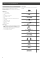
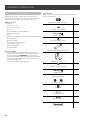
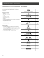
Parts supplied
Remove parts from packages. Check that all parts are
included.
Strain relief connector
2
4.2x8 mm screws
6
6-wire blower connector
1
4x1.8 mm flat washers
4
Rectangular bracket - Motor cover
2
Bracket- Connector support
1
6.3x60 mm screws
4
9-wire blower connector
1
Strain Reliefs
Ø 12 mm Ø 15.9 mm
1
6x13.5 mm
2
Torx 20 adapter
1
Torx 10 adapter
1
Strap 2.5x95 mm
2

5
Location Requirements
IMPORTANT: Observe all governing codes and ordinances.
Have a qualified technician install the in-line blower motor
system.
All openings in the ceiling and wall where the in-line blower
motor system will be installed must be sealed.
For Mobile Home Installations
The installation of this in-line blower motor system must
conform to the Manufactured Home Construction Safety
Standards, Title 24 CFR, Part 328 (formerly the Federal
Standard for Mobile Home Construction and Safety, Title
24, HUD, Part 280) or when such standard is not applicable,
the standard for Manufactured Home Installation 1982
(Manufactured Home Sites, Communities and Setups) ANSI
A225.1/NFPA 501A*, or latest edition, or with local codes.
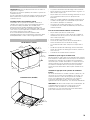
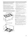
Product dimensions
14
7
⁄8”
(20 cm)
TOP (OUTLET) VIEW
BOTTOM (INLET) VIEW
3
3
⁄8”
(8.6 cm)
12
15
⁄16”
(32.9 cm)
26
1
⁄8”
(66.4 cm)
14
11
⁄16”
(37.3 cm)
24
3
⁄4”
(62.9 cm)
3
3
⁄8”
(8.6 cm)
14
7
⁄8”
(20 cm)
16
1
⁄8”
(41 cm)
Venting Requirements
• The vent system must terminate to the outdoors.
• Do not terminate the vent system in an attic or other
enclosed area.
• Do not use 4” (10.2 cm) laundry-type vent or wall caps.
• Use round, metal vent only. Rigid metal vent is
recommended. Plastic or metal foil vent is not
recommended.
• The length of the vent system and number of elbows
should be kept to a minimum to provide ecient
performance.
For the most efficient and quiet operation:
• Use no more than three 90° elbows.
• Make sure there is a minimum of 24” (61.0 cm) of straight
vent between the elbows if more than 1 elbow is used.
• Do not install 2 elbows together.
• Use clamps to seal all joints in the vent system.
• The vent system must have a damper.
• Use weatherproof caulking to seal the exterior wall or roof
opening around the cap.
• The size of the vent should be uniform.
Cold weather installations
An additional backdraft damper should be installed to
minimize backward cold air flow. A thermal break should be
installed to minimize conduction of outside temperatures as
part of the vent system. The damper should be on the cold air
side of the thermal break.
The thermal break should be as close as possible to where the
vent system enters the heated portion of the house.
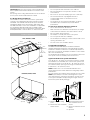
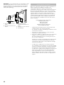
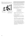
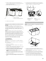
Typical In-line Blower System Installations
A 8” (20.32 cm) - 10” (25.4 cm) round vent system is needed
for installation (not included). The in-line blower system inlet
and outlet openings are 8” (20.32 cm) - 10” (25.4 cm) round.
The exhaust (outlet) opening on the range hood must also be
8” (20.32 cm) - 10” (25.4 cm) round.
NOTE: Flexible vent is not recommended. Flexible vent
creates back pressure and air turbulence that greatly reduce
performance.
The vent system can terminate either through the roof or wall.
NOTE: Plywood may be used as a mounting base to span
open areas between ceiling joists and rafters. If used, be sure
to use plywood capable of supporting the weight of the in-
line blower system (50 lb [22.6 kg]).
A
B
C
D
E
E
A. Mount on top of ceiling
joists.
B. Mount from cross-members
tied to trusses.
C. Duct horizontal; mount to
cross-members tied to
trusses.
D. Mount on underside of roof
rafters.
E. Plywood

6
Electrical Requirements
Observe all governing codes and ordinances.
Ensure that the electrical installation is adequate and in
conformance with National Electrical Code, ANSI/NFPA
70 (latest edition), or CSA Standards C22.1-94, Canadian
Electrical Code, Part 1 and C22.2 No. 0-M91 (latest edition)
and all local codes and ordinances.
If codes permit and a separate ground wire is used, it is
recommended that a qualified electrician determine that the
ground path is adequate.
A copy of the above code standards can be obtained from:
National Fire Protection Association
One Batterymarch Park
Quincy, MA 02269
CSA International
8501 East Pleasant Valley Road
Cleveland, OH 44131-5575
• A 120 volt, 60 Hz., AC only, 15-amp, fused electrical circuit
is required.
• If the house has aluminum wiring, follow the procedure
below:
1 Connect a section of solid copper wire to the pigtail leads.
2 Connect the aluminum wiring to the added section of
copper wire using special connectors and/or tools
designed and UL listed for joining copper to aluminum.
Follow the electrical connector manufacturer’s
recommended procedure. Aluminum/copper connection
must conform with local codes and industry accepted
wiring practices.
• Wire sizes and connections must conform with the rating
of the appliance as specified on the model/serial rating
plate. The model/serial plate is located behind the kit on
the rear wall.
• Wire sizes must conform to the requirements of the
National Electrical Code, ANSI/NFPA 70 (latest edition),
or CSA Standards C22. 1-94, Canadian Electrical Code,
Part 1 and C22.2 No. 0-M91 (latest edition) and all local
codes and ordinances.
INSTALLATION INSTRUCTIONS
Prepare Location
• Before making cutouts, make sure there is proper
clearance within the ceiling or wall for the exhaust vent.
• When cutting or drilling into the ceiling or wall, do not
damage electrical wiring or other hidden utilities.
• Check that all installation parts have been removed from
the shipping carton.
NOTE: For the correct performance of your In-Line Blower
System you must remove the Range Hood Internal Motor
Blower.
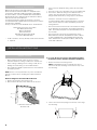
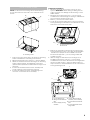
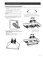
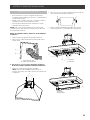
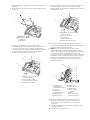
Remove Range Hood Internal Motor Blower
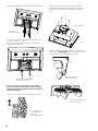
1 Remove grease filters from range hood.
2 Disconnect the blower power cord from de wire box.
B
A
A. Wire box connector
B. Power cord
A. For single Blower Motor Models (ECL630S4, EVV636S1,
EVV648S1, EVI642S1, EVI648S1, ELN630S2, EAR628S4)
1 Remove the blower mounting screws.
NOTE: for ELN630S2 range hood model you have to
remove the blower mounting screws from the top of the
hood housing.
A
A. Blower screws
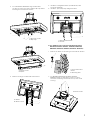
2 Set free the two blower springs from the top of the range
hood housing.

7
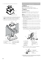
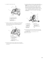
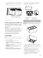
3 For or EVV648S1, EVV636S1 range hood models
you have to remove the spacer and the dip trays before
removing the internal motor blower.
A
B
A. Drip trays screws
B. Drip trays
A
B
A. Spacer screws
B. Spacer
4 Remove the range hood internal motor blower.
B
A
A. Blower
B. Blower screws
5 Install the rectangular brackets (included in kit) with
screws (4)4.2x8 mm.
6 Install the spacer, dip trays and grease filters.
B
A
A. Rectangular brackets
B. Screws
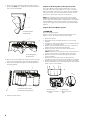
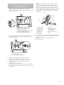
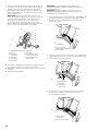
B. For dual Blower Motor Models (ECL136S4, ECL142S4,
ECL148S4, ELI142S2, ELI136S2, ETR134S1, EAR140S4,
EAR146S4, EAR134S4, ELN136S2, ELN142S2, ELN148S1)
1 Remove the filters, the mounting screws and lock washers.
A
B
A. Screw with locker
washer
B. Mounting Hole
2 For ELN136S2, ELN142S2, ELI136S2, ELI142S2,
EAR134S4 range hood models you have to remove
the blower mounting screws from the top of the hood
housing.
A. Blower screws
A

8
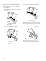
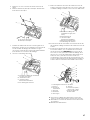
3 Remove the motor mounting plate by setting free the
spring clip. NOTE: The spring clip should be outside the
slot in the mounting plate.
A. Mounting plate
B. Spring Clip
A
B
A. Mounting plate
B. Spring Clip
A
B
4 Run out the power supply wires and connector through
the hole in the right end of the motor mounting plate.
5 Slide out the left mounting plate from under the motor
mounting bracket.
A
B
A. Motor mounting plate
B. Motor mounting bracket
6 Install the grease filters.
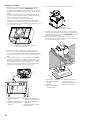
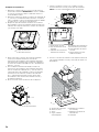
Prepare for Mounting the In-Line Blower System
The In-Line Blower System must be fastened to a secure
structure of the roof, ceiling, wall, floor, or new or existing
frame construction. The 4 holes on either the inlet (bottom)
side or the outlet (top) side of the blower must be used to
mount the in-line blower system to the structure.
NOTE: The mounting hole locations must span the studs.
Additional stud framing may be required. Plywood may be
used to span open areas between ceiling joists or roof rafters
to aid installation. This structure must be strong enough to
support the weight of the in-line blower system (50 lb [22.6
kg] min).
Prepare the In-line Blower System
I WARNING
Excessive Weight Hazard
Use two or more people to move and install range hood.
Failure to do so can result in back or other injury.
1 Disconnect power.
2 Determine which venting method to use: roof or wall
exhaust.
3 Using two or more people, move the in-line blower motor
system to the mounting location.
4 Remove the 10 screws from the front cover of the in-line
blower motor housing and set them aside.
5 Remove the front cover of the in-line blower motor
housing and set it aside.
NOTE: To make the in-line blower motor housing easier to
mount, the blower motor assembly can be removed.
6 Disconnect the motor electrical plug from the blower
motor assembly.
7 Remove the screws that secure the blower motor
assembly to the in-line blower housing and set them aside.
8 Pull the spring clip to release the blower motor assembly.
Remove the blower motor assembly from the housing and
place it on a covered surface.
A
B
C
D
A. Front cover
B. Blower mounting
screws
C. Spring clip
D. Motor electrical
plug

9
Install In-Blower System
NOTE: The blower motor housing can be mounted using
4 holes from either the inlet side or the outlet side of the
blower.
A
A
A
A
A
A
A. Mounting holes
1 Position the in-line blower motor housing in its mounting
location and mark the 4 mounting hole locations.
2 Drill 4 mounting pilot holes using a ³⁄₁₆” (0.5 cm) drill bit.
3 Attach the in-line blower motor housing to the mounting
location with mounting (4) 6.3x60 mm screws and
(4)4x1.8 washers(Parts are included with the range hood
motor kit)
4 If removed, reinstall the blower motor assembly and
secure it with the screws previously removed.
5 If removed, reattach the motor electrical plug to the
connector on the blower motor assembly.
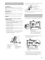
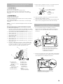
Complete Preparation
1 Determine and make all necessary cuts for the vent
system. IMPORTANT: When cutting or drilling into the
ceiling or wall, do not damage electrical wiring or other
hidden utilities.
2 Determine the location where the ¹⁄₂” (1.3 cm) wiring
conduit will be routed through the ceiling or wall between
the in-line blower and the range hood.
3 Drill a 1¹⁄₄” (3.2 cm) hole at this location.
4 Locate the electrical terminal boxes in the in-line blower
housing and range hood. Remove the terminal box covers
and set the covers and screws aside.
A
B
A. Terminal Box Cover
B. Knockout
5 Remove the electrical knockout from the in-line blower
housing and range hood (see the range hood installation
instructions) to prepare for the installation of the UL
listed or CSA approved ¹⁄₂” (1.3 cm) wiring conduit and
conduit connector.
6 With the range hood mounted (see the range hood
installation instructions), run the ¹⁄₂” (1.3 cm) wiring
conduit between the in-line blower motor housing and the
range hood. Pull enough ¹⁄₂” wiring conduit to allow for
easy connection to the terminal boxes in the in-line blower
housing and range hood.
A
B
C
D
F
E
A. In-Line Blower Kit
B. Range Hood Terminal
Box
C. Power Supply wiring
Conduit
D. In-Line Blower Wiring
Conduit (not included)
E. In-Line Blower Terminal
Box
F. In-Line Motor Electrical
Plug Cable

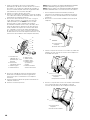
10
7 If necessary remove the range hood transition.
A
B
A. Transition
B. Transition screws
8 Install the conduit connectors and conduit to the in-line
blower housing and range hood electrical terminal boxes.
NOTE: If removed, install the range hood transition.
9 Connect the vent system to the range hood and in-line
blower system and seal all joints with clamps.
F
E
B
G
A
C
D
A. Vent System
B. In line Blower Motor
C. Ceiling
D. Roof rafters/ Plywood
E. In line Blower Wiring
Conduit (not included)
F. Power Supply Wiring
Conduit
G. Hood Insert
Make Electrical Connection for In-Line Blower
Motor System
I WARNING
Electrical Shock Hazard
Disconnect power before servicing.
Replace all parts and panels before operating.
Failure to do so can result in death or electrical shock.
I WARNING
Electrical Shock Hazard
Electrically ground blower.
Connect ground wire to green and yellow ground wire in
terminal box.
Failure to do so can result in death or electrical shock.
NOTE: The electrical diagram is attached at the end of the
document.
Electrical Connection Inside In-line Blower System
1 Disconnect power.
2 Connect the wires from the wiring conduit to the wires
from the motor electrical plug cable inside the in-line
blower housing terminal box.
3 Use UL listed wire connectors and connect the black wires
(C) together.
4 Use UL listed wire connectors and connect the white wires
(D) together.
5 Use UL listed wire connectors and connect the red wires
(E) together.
6 Use UL listed wire connectors and connect the blue wires
(F) together.
7 Use UL listed wire connectors and connect the gray wires
(G) together.
8 Connect the green (or green/yellow) ground wire from the
wiring conduit to the green (or yellow/green), ground wire
(H) in the terminal box using UL listed wire connectors.
A
B
C
D
E
F
G
H
I
A. Strain relief
B. UL listed wire
connectors
C. Black wires
D. White wires
E. Red wires
F. Blue wires
G. Gray wires
H. Green (or yellow/
green) and green /
yellow wires
I. Motor electrical plug
cable
9 Once the connection is done, is necessary to adjust the
9-6 wire connector with the included strap.
A. Ground wires
connection
B. 6-9 wire connector
C. Strap
D. Strain relief
A
B
C
D
10 Reinstall the in-line blower terminal box cover and screws.
11 Reinstall the front cover of the in-line blower housing and
secure it with 10 mounting screws.

11
Make Electrical Connection Inside Range Hood
Between In-Line Blower System
and Range Hood
1 With the range hood mounted (see the range hood
installation instructions), locate the wiring cable connector
inside the range hood.
C
D
A
B
A. Range Hood Junction Box
B. Range Hood knockout for Wire
Connector Assembly
C. Wire Connector Assembly (provided
in the In-Line Blower Kit)
D. Power Supply Wiring Conduit
2 Connect the 6 wire connector assembly supplied with
the in-line blower motor system to the mating connector
from the range hood.
B
A
A. Wire Connector Assembly (provided in
the In-Line Blower Kit)
B. Hood Insert Blower Connector
3 Install UL listed or CSA approved strain reliefs. Run
through the strain reliefs the 6 wire connector
and the In-Line Blower wiring conduit (not incluided
leaving enough wire length to make the wiring
connections.
4 Tighten the strain relief screws.
5 Connect the wires from the 6- wire connector assembly
to the wires from the wiring conduit inside the range hood
terminal box.
NOTE: Connect the green (or green/yellow) ground
wire from the wiring conduit to the green (or bare)
ground wire from the home power supply and to the
and to the green/yellow ground wire from the 6-wire
connector assembly (H) using UL listed wire connectors
(see the “Make Electrical Power Supply Connections
to Range Hood” section in the range hood installation
instructions).
A
B
C
D
E
F
G
H
I
A. Strain relief
B. UL listed wire
connectors
C. Black wires
D. White wires
E. Red wires
F. Blue wires
G. Gray wires
H. Green (or yellow/
green) and green /
yellow wires
I. Motor electrical plug
cable
6 Connect the home power supply wiring to the range
hood following the instructions that are supplied with the
range hood.
7 Reinstall the range hood terminal box cover.
8 Reconnect power.

12
NOTE: For the Range Hood Models EVV636S1, EVV648S1,
EVI642S1, EVI648S1 follow the next instructions.
NOTE: For the Range Hood Models EVV636S1, EVV648S1,
EVI642S1, EVI648S1 use de 9 wire connector assembly and
the 15.9mm strain relief.
1 With the range hood mounted (see the range hood
installation instructions), locate the wiring cable connector
inside the range hood.
2 Disconnect the Hood Insert Blower Connector.
A. Hood Insert
Blower Connector
B. Hood Smart
B
A
3 Install the connector support bracket with screws
(2)4.2x8mm included in kit; put the hood blower
connector in the cavity of the bracket.
A. Hood Blower
Connector
B. Connector support
bracket
B
A
4 Connect the 9-wire connector assembly supplied with
the in-line blower motor system to the mating connector
from the range hood.
A
B
A. Hood Insert
Blower Connector
B. 9 Wire Connector
5 Remove the screws and cover of the hood terminal box.
6 Remove the knockout from the top of the hood terminal
box .
A
B
A. Terminal box cover
B. Knockout
7 Install UL listed or CSA approved strain reliefs. Run
through the strain reliefs the 9 wire connector
and the In-Line Blower wiring conduit (not incluided
leaving enough wire length to make the wiring
connections.

13
8 Tighten the strain relief screws.
B
A
C
D
A. In-Line Blower wiring
conduit (not incluided)
B. 6-9 wire connector
C. Hood Insert
Blower Connector
D. Strain reliefs
9 Remove the strain relief of the Range Hood terminal box,
and run trhough the green (or green/yellow) ground
wire from the wiring conduit. Install and tighten the
removed strain relief.
A. In-Line Blower wiring conduit
(not incluided)
B. 6-9 wire connector
C. Hood Insert
Blower Connector
D. Range Hood strain relief
E. Strain relief
A
B
C
D
E
10 Connect the wires from the 9-wire connector assembly
to the wires from the wiring conduit inside the range hood
terminal box.
11 Connect the same color wires to each other (black to
black, white to white, etc.) using UL listed wire connectors.
NOTE: Connect the green (or green/yellow) ground
wire from the wiring conduit to the green (or bare)
ground wire from the home power supply and to the
and to the green/yellow ground wire from the 9-wire
connector assembly (H) using UL listed wire connectors
(see the “Make Electrical Power Supply Connections
to Range Hood” section in the range hood installation
instructions).
A
B
C
D
E
F
G
H
I
A. Strain relief
B. UL listed wire
connectors
C. Black wires
D. White wires
E. Red wires
F. Blue wires
G. Gray wires
H. Green (or yellow/
green) and green /
yellow wires
I. Motor electrical plug
cable
12 Connect the home power supply wiring to the range
hood following the instructions that are supplied with
the range hood.
13 Reinstall the range hood terminal box cover.
14 Reconnect power.

14
ELICA North America
TWO-YEAR LIMITED WARRANTY
TO OBTAIN SERVICE UNDER WARRANTY
Owner must present proof of original purchase date. Please keep a copy of your dated proof of purchase (sales slip) in
order to obtain service under warranty.
PARTS AND SERVICE WARRANTY
For the period of two (2) years from the date of the original purchase, Elica will provide free of charge, non consumable
parts or components that failed due to manufacturing defects. During these two (2) years limited warranty, Elica will also
provide free of charge, all labor and in-home service to replace any defective parts.
WHAT IS NOT COVERED
• Damage or failure to the product caused by accident or act of God, such as, flood, fire or earthquake.
•
Damage or failure caused by modification of the product or use of non-genuine parts.
• Damage or failure to the product caused during delivery, handling or installation.
• Damage or failure to the product caused by operator abuse.
• Damage or failure to the product caused by dwelling fuse replacement or resetting of circuit breakers.
• Damage or failure caused by use of product in a commercial application.
• Service trips to dwelling to provide use or installation guidance.
• Light bulbs, metal or carbon filters and any other consumable part.
• Normal wear of finish.
• Wear to finish due to operator abuse, improper maintenance, use of corrosive or abrasive cleaning products/pads and
oven cleaner products.
WHO IS COVERED
This warranty is extended to the original purchaser for products purchased for ordinary residential use in North America
(Including the United States, Guam, Puerto Rico, US Virgin Islands & Canada).
This warranty is non-transferable and applies only to the original purchaser and does not extend to subsequent owners of
the product. This warranty is made expressly in lieu of all other warranties, expressed or implied, including, but not limited
to any implied warranty of merchantability or fitness for a particular purpose and all other obligations on the part of Elica
North America, provided, however, that if the disclaimer of implied warranties is ineective under applicable law, the dura
-
tion of any implied warranty arising by operation of law shall be limited to two (2) years from the date of original purchase
at retail or such longer period as may be required by applicable law.
This warranty does not cover any special, incidental and/or consequential damages, nor loss of profits, suered by the
original purchaser, its customers and/or the users of the Products.
WHO TO CONTACT
To obtain service under warranty or for any service related question:
• Elica North America Service, call at 1 888 732 8018
• For Eastern Canada, call AGI Services at 1 888 651 2534 Ask for the service department
• elica@servicepower.com
Register your product in
elica.com
and earn a 3
rd
year of factory
warranty, covering all parts
plus in-home labor.

15

16
FRANÇAIS
Contents
Avis de sécurité important.......................................................................................................................................................................................... 17
Exigendes D´installation ............................................................................................................................................................................................ 18
Outils et pièces ........................................................................................................................................................................................................... 18
Exigences d’emplacement. ..................................................................................................................................................................................... 19
Dimensions du Produit ........................................................................................................................................................................................... 19
Exigences concernant lévacuation ...................................................................................................................................................................... 19
Specifications electriques ..................................................................................................................................................................................... 20
Instructions d´installation ........................................................................................................................................................................................... 21
Preparatioon de l´emplacement ......................................................................................................................................................................... 21
Installer le Système de Souante en Ligne .................................................................................................................................................... 23
Faire le Raccordement Électrique pour le Système de Moteur de Souante en Ligne ................................................................ 25
Raccordement électrique à l’intérieur de la hotte de cuisine entre un
Système de Souante en ligne et une hotte de cuisinière ...................................................................................................................... 25
GARANTIE ......................................................................................................................................................................................................................... 28
SCHÉMA DE CÂBLAGE................................................................................................................................................................................................. 43
APPROUVÉ POUR LES APPAREILS DE TYPE RÉSIDENTIEL
POUR UNE UTILISATION RÉSIDENTIELLE SEULEMENT
LISEZ CES INSTRUCTIONS ET CONSERVEZ-LES
VEUILLEZ LIRE CES INSTRUCTIONS AU COMPLET AVANT DE COMMENCER.
L’INSTALLATION DE L’APPAREIL DOIT RESPECTER TOUS LES CODES EN VIGUEUR.
IMPORTANT : Conservez ces instructions afin de pouvoir les remettre à l’inspecteur-électricien de votre région.
INSTALLATEUR : Veuillez laisser ces instructions avec l’appareil pour le propriétaire.
PROPRIÉTAIRE : Veuillez conserver ces instructions pour pouvoir vous y référer plus tard.
Avertissement de sécurité : Coupez l’alimentation du circuit dans le panneau électrique et verrouillez le
panneau avant de raccorder les fils de cet appareil.
Exigence : 120 V c.a., 60 Hz circuit de dérivation de 15 V c.a., 20 Hz, de 15 ou 20 A.

17
I
AVIS DE SÉCURITÉ IMPORTANT
I ATTENTION
UTILISER CET APPAREIL À DES FINS DE VENTILATION
GÉNÉRALE SEULEMENT. NE PAS UTILISER CET APPAREIL
POUR ÉVACUER DES MATÉRIAUX OU DES VAPEURS
DANGEREUX OU EXPLOSIFS.
I AVERTISSEMENT
POUR RÉDUIRE LES RISQUES D’INCENDIE, DE CHOC
ÉLECTRIQUE ET DE BLESSURE, RESPECTER LES DIRECTIVES
SUIVANTES:
A. Utiliser cet appareil uniquement aux fins prévues par le
fabricant. Si vous avez des questions à propos de l’appareil,
communiquez avec le fabricant.
B. Avant de faire l’entretien de l’appareil ou de le nettoyer,
coupez l’alimentation dans le panneau électrique et
verrouillez le panneau en bloquant le dispositif permettant
d’empêcher d’activer l’alimentation accidentellement. S’il
n’est pas possible de verrouiller l’accès au panneau, fixez
une étiquette très voyante au panneau électrique.
C. Une personne qualifiée doit eectuer l’installation et le
câblage des fils électriques en conformité avec tous les
codes et toutes les normes, y compris la cote de résistance
au feu.
D. Il est important de prévoir susamment d’air pour assurer
une bonne combustion de l’équipement de chaue et l’éva-
cuation adéquates des gaz par le conduit de cheminé afin
de prévenir les refoulements d’air. Respectez les directives
et les normes de sécurité des fabricants de l’équipement
de chauage, comme celles publiées par la National Fire
Protection Association (NFPA), la American Society for
Heating, Refrigeration and Air Conditioning Engineers (AS-
HRAE) et le code des autorités de votre région.
E. Au moment de couper ou de percer un mur ou un plafond,
assurez-vous de ne pas endommager la filerie électrique
ou tout autre accès à un service publique.
F. Il faut toujours évacuer à l’extérieur les systèmes conduit.
I ATTENTION
Pour réduire les risques d’incendie et évacuer l’air correctement,
assurez-vous que le conduit mène à l’extérieur; il ne faut pas
évacuer l’air dans l’espace entre les murs, dans les plafonds, dans
les greniers, les vides sanitaires ou les garages.
I AVERTISSEMENT
POUR RÉDUIRE DES RISQUES D’INCENDIE, UTILISEZ
UNIQUEMENT DES CONDUITS EN MÉTAL.
Installez cette hotte en respectant toutes les exigences
mentionnées.
I AVERTISSEMENT
Pour réduire les risques d’incendie et de choc électrique,
n’utilisez pas cette hotte avec un contrôleur de vitesse à
semi-conducteurs.
I AVERTISSEMENT
POUR RÉDUIRE LES RISQUES D’INCENDIE DE GRAISSE SUR
LES CUISINIÈRES.
a) Ne laissez jamais la cuisinière sans surveillance lorsqu’elle
est réglée à une haute température. Les débordements par
bouillonnement causent de la fumée et des débordements
de gras qui peuvent s’enflammer. Faites chauer l’huile
lentement, à une température basse ou moyenne.
b) Faites toujours fonctionner la hotte lorsque vous utilisez
la cuisinière à une haute température ou que vous faites
flamber des aliments (P. ex.: crêpes Suzette, cerises
jubilées, boeuf au poivre flambé).
c) Nettoyez les hélices de ventilation fréquemment. Il ne faut
pas que la graisse s’accumule sur les filres ou les hélices.
d) Utilisez le bon format de casserole. Utilisez toujours un
chaudron de taille approprié à l’élément de la cuisinière.
e) Convient pour utilisation dans la zone de cuisson domestique.
I AVERTISSEMENT
POUR ÉVITER DE BLESSER QUELQU’UN LORS D’UN
INCENDIE DE GRAISSE SUR LA CUISINIÈRE, SUIVRE LES
CONSEILS SUIVANTS:
a
a) ÉTOUFFER LES FLAMMES avec un couvercle aux
dimensions de la taque de cuisson, une tôle à biscuit ou
tout autre plateau métallique, puis couper le gaz ou
l’alimentation électrique de la cuisinière. FAIRE ATTENTION
A NE PAS SE BRÛLER. Si les flammes ne s’éteignent pas
immédiatement, QUITTER LA PIÈCE ET APPELER LES
POMPIERS.
b) NE JAMAIS PRENDRE EN MAIN UNE CASSEROLE N FEU,
vous pourriez vous blesser.
c) NE PAS UTILISER D’EAU, y compris les essuies de vaisselle
ou les serviettes humides – une violente explosion due à la
vapeur formée pourrait survenir.
d) Utiliser un extincteur SEULEMENT si:
1) Vous êtes sûr d’avoir un extincteur de classe ABC que
vous savez utiliser.
2) Le feu est petit et confiné à la zone où il s’est formé.
3) Les pompiers ont été appelés.
4) Vous pouvez lutter contre le feu avec une sortie
derrière vous.
a Recommandations tirées des conseils de sécurité en cas d’incendie de cuisine
publiés par la NFPA.
I AVERTISSEMENT
Pour réduire les risques d’incendie, de choc électrique et de
blessure des personnes, le kit, modèle KIT0154387, doit être
installé avec les hottes de cuisinières suivantes. Les autres
fourchettes ne peuvent pas être substituées:
ECL630S4, ECL136S4, ECL142S4, ECL148S4, EVV636S1
EVV648S1, EVI642S1, EVI648S1, ELN630S2,
ELN136S2, ELN142S2, ELN148S1, ELI142S2, ELI136S2,
ETR134S1,EAR140S4, EAR146S4, EAR628S4, EAR134S4.

18
EXIGENCES D´INSTALLATION
Outils et pièces
Rassembler les outils et composants nécessaires avant
d’entreprendre l’installation. Lire et observer les instructions
fournies avec chacun des outils de la liste ci-dessous.
Outils nécessaires
• Perceuse
• Foret de 1¼” (3 cm)
• Foret de ³⁄₁₆” (0,5 cm)
• Crayon
• Pince à dénuder ou couteau utilitaire
• Mètre-ruban ou règle
• Pince
• Pistolet à calfeutrage et composé de calfeutrage résistant
aux intempéries
• Brides de conduit
• Scie sauteuse ou scie à guichet
• Tournevis à lame plate
• Cisaille de ferblantier
• Tournevis Phillips
Pièces nécessaires
• 6-9 conducteurs de calibre 18 AWG de chacune des
couleurs suivantes : noir, blanc, rouge, bleu, gris et vert
ou vert/jaune (terre). REMARQUE: La longueur du
conduit et des cables AWG est d.terminée par la distance
entre le moteur du ventilateur interne et les botiers de
raccordement de la hotte.
• 11 connecteurs de fils homologués UL
Pièces fournies
Retirer les pièces de leur emballage. Vérifier que toutes les
pièces sont présentes.
Décharge de traction connector
2
4.2x8 mm vis de montage
6
6 -Câble de prise
1
4x1.8 mm rondelles plates
4
Supports rectangulaires Moteur cover
2
Support de connecteur
1
6.3x60 mm vis de montage
4
9 -Câble de prise
1
Décharge de traction
Ø 12 mm Ø 15.9 mm
1
6x13.5 mm
2
Torx 20 adaptateur
1
Torx 10 adaptateur
1
Sangle 2.5x95 mm
2

19
Exigences d’emplacement
IMPORTANT: Observer les dispositions de tous les codes et
règlements en vigueur.
Recourir à un technicien qualifié pour installer le système de
ventilation interne.
Assurer l’étanchéité au niveau de chaque ouverture découpée
dans le plafond ou le mur pour l’installation du système de
ventilation interne.
Installation dans une résidence mobile
L’installation de ce système de ventilation interne doit
satisfaire aux exigences de la norme Manufactured Home
Construction Safety Standards, Titre 24 CFR, partie
328 (anciennement Federal Standard for Mobile Home
Construction and Safety, titre 24, HUD, partie 280) ; lorsque
cette norme n’est pas applicable, l’installation doit satisfaire
aux critères de la plus récente édition
de la norme Manufactured Home Installation 1982
(Manufactured Home Sites, Communities and Setups) ANSI
A225.1/NFPA 501A*, ou des codes et règlements locaux.
Dimension du produit
14
7
⁄8”
(20 cm)
VUE DE DESSUS (SORTIE)
VUE DE DESSOUS (ENTRÉE)
3
3
⁄8”
(8.6 cm)
12
15
⁄16”
(32.9 cm)
26
1
⁄8”
(66.4 cm)
14
11
⁄16”
(37.3 cm)
24
3
⁄4”
(62.9 cm)
3
3
⁄8”
(8.6 cm)
14
7
⁄8”
(20 cm)
16
1
⁄8”
(41 cm)
Exigences concernant l’évacuation
• Le système d’évacuation doit décharger l’air à l’extérieur.
• Ne pas terminer le circuit d’évacuation dans un grenier ou
dans un autre espace clos.
• Ne pas utiliser une bouche de décharge murale de 4” (10,2
cm) normalement utilisée pour un équipement de
buanderie.
• Utiliser un conduit métallique cylindrique uniquement. Un
conduit en métal rigide est recommandé. Ne pas utiliser
de conduit en plastique ou aluminium.
• La longueur du conduit de décharge et le nombre de
coudes doivent être réduits au minimum pour obtenir les
meilleurs résultats.
Pour un fonctionnement efficace et silencieux :
• Ne pas utiliser plus de trois coudes à 90°.
• Veiller à ce qu’il y ait une section droite de conduit d’un
minimum de 24” (61 cm) entre les raccords coudés, si on
doit en utiliser plus d’un.
• Ne pas installer 2 coudes successifs.
• Au niveau de chaque jointure du circuit d’évacuation,
assurer l’étanchéité avec les brides de serrage.
• Le circuit d’évacuation doit comporter un clapet anti-re
flux.
• À l’aide d’un produit de calfeutrage, assurer l’étanchéité
autour de la bouche de décharge à l’extérieur (à travers le
mur ou le toit).
• Le diamètre du conduit doit être uniforme.
Installations pour régions à climat froid
On doit installer un clapet anti-retour supplémentaire à l’arrièr
pour minimiser le reflux d’air froid et incorporer une résistance
thermique pour minimiser la conduction des températures
extérieures par le conduit d’évacuation. Le clapet anti-retour
doit être placé du côté air froid de la résistance thermique.
La résistance thermique doit être le plus près possible de
l’entrée du circuit d’évacuation dans la partie chauffée de la
maison.
Installations typiques d’un système de ventilation
interne
Un circuit d’évacuation en conduit rond de 8” (20.32 cm) - 10”
(25,4 cm) est nécessaire pour l’installation (non fourni). Les
ouvertures d’entrée et de sortie du système de ventilation
interne ont un diamètre de 8” (20.32 cm) - 10” (25,4 cm).
L’ouverture de décharge (sortie) sur la cuisinière doit
également mesurer 8” (20.32 cm) - 10” (25,4 cm) de diamètre.
REMARQUE : On déconseille l’emploi d’un conduit flexible. Un
conduit flexible peut causer une contre-pression et des
turbulences d’air, qui réduisent considérablement la
performance. La sortie à l’extérieur du circuit d’évacuation
peut se faire à travers le toit ou un mur.

20
REMARQUE : Il est possible d’utiliser du contreplaqué comme
base de montage dans les zones ouvertes entre solives et
chevrons. Dans un tel cas, veiller à utiliser du contreplaqué
capable de supporter le poids du système de ventilation
interne (50 lb [22,6 kg]).
A
B
C
D
E
E
A. Montage au-dessus des
solive
B. Montage sur traverses de
ferme
C. Conduit horizontal,
montage sur traverses de
ferme
D. Montage sous les chevrons
E. Contreplaqué
Spécifications électriques
Observer les dispositions de tous les codes et règlements en
vigueur. Vérifier que l’installation électrique a été
correctement eectuée et qu’elle est conforme aux
spécifications de la plus récente édition des normes National
Electrical Code, ANSI/NFPA 70, ou de la norme CSA C22.1-
94, Code canadien de l’électricité, partie 1 et C22.2 N° 0-M91
(dernière édition) et de tous les codes et règlements en
vigueur locaux. Si les codes le permettent et si on utilise un
conducteur distinct de liaison à la terre, il est recommandé
qu’un électricien qualifié vérifie la qualité de la liaison à la
terre. Pour obtenir un exemplaire de la norme des codes ci-
dessus, contacter :
National Fire Protection Association
One Batterymarch Park
Quincy, MA 02269
CSA International
8501 East Pleasant Valley Road
Cleveland, OH 44131-5575
• L’appareil doit être alimenté par un circuit de 120 V, CA
seulement, 60 Hz, 15 A, protégé par fusible.
• Si le domicile est équipé d’un câblage en aluminium, suivre
les instructions suivantes :
1 Connecter une section de câble en cuivre massif aux
conducteurs en queue de cochon.
2 Connecter le câblage en aluminium à la section ajoutée de
câblage en cuivre en utilisant des connecteurs et/ou
des outils spécialement conçus et homologués UL pour
fixer le cuivre à l’aluminium.
Appliquer la procédure recommandée par le fabricant des
connecteurs. La connexion aluminium/cuivre doit être
conforme aux codes locaux et aux pratiques de câblage
acceptées par l’industrie.
• Le calibre des conducteurs et les connexions doivent
être compatibles avec la demande de courant de l’appareil
spécifiée sur la plaque signalétique. La plaque signalétique
de l’appareil est située à l’intérieur du boîtier du moteur.
• Le calibre des conducteurs doit satisfaire aux exigences de
la plus récente édition de la norme National Electrical
Code, ANSI/NFPA 70, ou de la norme CSA C22.1-94,
Code canadien de l’électricité, partie 1 et C22.2 n° 0-M91
(dernière édition) et de tous les codes et règlements en
vigueur.
La page est en cours de chargement...
La page est en cours de chargement...
La page est en cours de chargement...
La page est en cours de chargement...
La page est en cours de chargement...
La page est en cours de chargement...
La page est en cours de chargement...
La page est en cours de chargement...
La page est en cours de chargement...
La page est en cours de chargement...
La page est en cours de chargement...
La page est en cours de chargement...
La page est en cours de chargement...
La page est en cours de chargement...
La page est en cours de chargement...
La page est en cours de chargement...
La page est en cours de chargement...
La page est en cours de chargement...
La page est en cours de chargement...
La page est en cours de chargement...
La page est en cours de chargement...
La page est en cours de chargement...
La page est en cours de chargement...
La page est en cours de chargement...
-
 1
1
-
 2
2
-
 3
3
-
 4
4
-
 5
5
-
 6
6
-
 7
7
-
 8
8
-
 9
9
-
 10
10
-
 11
11
-
 12
12
-
 13
13
-
 14
14
-
 15
15
-
 16
16
-
 17
17
-
 18
18
-
 19
19
-
 20
20
-
 21
21
-
 22
22
-
 23
23
-
 24
24
-
 25
25
-
 26
26
-
 27
27
-
 28
28
-
 29
29
-
 30
30
-
 31
31
-
 32
32
-
 33
33
-
 34
34
-
 35
35
-
 36
36
-
 37
37
-
 38
38
-
 39
39
-
 40
40
-
 41
41
-
 42
42
-
 43
43
-
 44
44


dans d''autres langues
- English: ELICA ECL142S4 Installation guide
- español: ELICA ECL142S4 Guía de instalación
Documents connexes
-
ELICA EVV636S1 Guide d'installation
-
ELICA ELN630S2 Le manuel du propriétaire
-
ELICA ETR134S1 Mode d'emploi
-
-
ELICA ECL148S4 Guide d'installation
-
-
-
-
