La page est en cours de chargement...

IS-44315-CB
We’re here to help 866-558-5706
Hrs: M-F 9am to 5pm EST
7) Connect mounng strap[G] to outlet box using strap
mounng screws[L]
8) Unscrew the threaded ring from screw collar loop. Take
canopy[I] and pass over screw collar loop. Approximately
one half of the screw collar loop exterior threads should
be exposed. Adjust screw collar loop by turning assembly
up or down in mounng strap. Remove canopy.
9) Aer desired posion is found, ghten both top and
boom hexnuts up against the boom and top of the
mounng strap.
10) Slip canopy over screw collar loop and thread on
threaded ring. Aach chain link[J] (with xture
connected) to boom of screw collar loop. Unscrew
threaded ring[K], let canopy and threaded ring slip
down. (Close chain link ends together using chain pliers
or padded pliers to prevent damage to nish.)
11) Aach open chain link[J] to small loop at end of each
stem and to each loop on canopy and close the open
chain link by threading the nut down onto the link end.
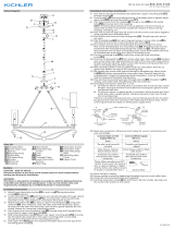
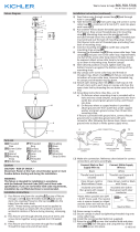
12) Grounding instrucons: (See Illus. a or b).
a) On xtures where mounng strap is provided with a
hole and two raised dimples, wrap ground wire from
outlet box around green ground screw, and thread
into hole.
b) On xtures where a cupped washer is provided,
aach ground wire from outlet box under cupped
washer and green ground screw, then thread into
mounng strap.
If xture is provided with ground wire, connect xture
ground wire to outlet box ground wire with wire
connector (Not provided) aer following the above steps.
Never connect ground wire to black or white power
supply wires.
13) Make wire connecon. Reference chart below for correct
connecons and wire accordingly.
Connect Black or Red
Supply Wire to:
Connect White Supply
Wire to:
Black White
*Parallel cord (round &
smooth)
*Parallel cord (square &
ridged)
Clear, Brown, Gold or
Black without Tracer
Clear, Brown, Gold or Black
with Tracer
Insulated wire (other
than green) with copper
conductor
Insulated wire (other
than green) with silver
conductor
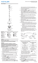
*Note: When parallel wire (SPT
1 & SPT 2) are used. The neutral
wire is square shaped or ridged
and the other wire will be round
in shape or smooth (See illus.)
Neutral Wire
14) Thread on the top loop onto the main body.
15) Raise canopy to ceiling.
16) Secure canopy in place by ghtening threaded ring onto
screw collar loop.
17) Lower the glass shades[N] onto each socket as shown.
Note that there are two (2) dierent sizes of the glass
shades.
18) Install the recommended bulbs (Not supplied).
GREEN GROUND
SCREW
CUPPED
WASHER
OUTLET BOX
GROUND
FIXTURE
GROUND
DIMPLES
WIRE CONNECTOR
OUTLET BOX
GROUND
GREEN GROUND
SCREW
FIXTURE
GROUND
a
b
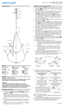
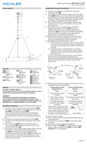
Fixture Diagram
Parts List
[A] Coupling
[B] Stem
[C] Threaded
Tubes
[D] First loop
[E] Second Loop
[F] Hexnut
[G] Mounting
Strap
[H] Outlet Box
[I] Canopy
[J] Chain Link
[K] Threaded
Ring
[L] Strap
Mounting
Screws
[M] Screw Collar
Loop
[N] Glass Shades
Cauons
CAUTION – RISK OF SHOCK –
Disconnect Power at the main circuit breaker panel or main
fusebox before starng and during the installaon.
WARNING:
This xture is intended for installaon in accordance
with the Naonal Electrical Code (NEC) and all local code
specicaons. If you are not familiar with code requirements,
installaon by a cered electrician is recommended.
Installaon Instrucons
Installaon Instrucons (connued)
1) Pass xture wire from the coupling[A] on top of xture
through a stem[B] and threaded tubes[C] and screw
stem into coupling. NOTE: Thread locking compound
must be applied to all stem threads as noted with (4)
symbol to prevent accidental rotaon of xture during
cleaning, relamping, etc.
2) Pass xture wire through desired amount of stems and
screw stems together using supplied short threaded
tubes.
3) Pass xture wire from last stem through rst loop[D].
Thread rst loop onto end of last stem.
4) Pass xture wire through second loop[E] and through
hole in canopy[I].
5) Take threaded pipe from parts bag and screw in screw
collar loop[M] a minimum of 6 mm (1/4”). Lock into place
with hexnut[F].
6) Run another hexnut down threaded pipe almost touching
rst hexnut. Now screw threaded pipe into mounng
strap[G]. Mounng strap must be posioned with
extruded thread faced into outlet box[H]. Threaded pipe
must protrude out the back of mounng strap. Screw
third hexnut onto end of threaded pipe protruding from
back of mounng strap.
H
G
F
L
N
I
M
K
J
►
D
B
C
►
►
►
A
N
E

IS-44315-CB
Nous sommes là pour vous aider 866-558-5706
Heures : du lundi au vendredi, de 9h à 17h (heure de l’Est)
INSTRUCTIONS:
For Assembling and Installing Fixtures in Canada
Pour L’assemblage et L’installaon Au Canada
ges et de vis ges ensemble à l’aide de tubes letés
courts fournis.
3) Passer le l de la dernière ge à travers la première
boucle. Fil première boucle[D] sur l’extrémité de la
dernière ge.
4) Passer le l du luminaire à travers la deuxième boucle [E]
et à travers le trou dans couvercle[I].
5) Prendre leté raccord du sac de pièces et des vis dans la
boucle de col vissé[M] un minimum de 6 mm (1/4 po).
Fixer avec l’écrou hexagonal[F].
6) Couler un autre écrou hexagonal raccord leté touchant
presque le premier écrou hexagonal. Maintenant visser
tuyau leté sur une courroie de xaon[G]. Sangle de
xaon doit être posionné avec l extrudé rencontré
en boîte de sore[H]. Raccord leté doit dépasser
de l’arrière de la sangle de xaon. Troisième écrou
hexagonal sur l’extrémité du raccord à vis qui dépassent
de l’arrière de la sangle de xaon à vis.
7) Fixez la bride de montage à la boîte de sore à l’aide des
vis de xaon de la courroie[L].
8) Dévisser la bague letée du collier à vis. Passer le cache
[I]sur le collier à vis. La moié du letage extérieur du
collier à vis doit être visible. Ajuster le collier à vis en
tournant l’ensemble vers le haut ou le bas dans la bride
de montage. Enlever le cache.
9) Une fois bien posionné, serrer les écrous hexagonaux
en haut et en bas contre le dessous et le dessus de la
bride de montage.
10) Passer le cache sur le collier à vis et visser la bague
letée. Fixer la chaîne ouvert[J] (avec le luminaire
connecté) sur la pare inférieure du collier à vis. Dévisser
la bague letée[K], laisser le cache et la bague letée
glisser vers le bas. (Fermer les extrémités de maillon
ensemble à l’aide de pinces à chaîne ou de pinces
rembourrées pour ne pas endommager la nion).
11) Aachez le maillon de chaîne ouvert [J] à la pete
boucle à l’extrémité de chaque ge et à chaque boucle
de la verrière et fermez le maillon de la chaîne ouverte
en enlant l’écrou sur l’extrémité du maillon.
12) Connecter les ls. Se reporter au tableau ci-dessous pour
faire les connexions.
Connecter le l noir ou
rouge de la boite
Connecter le l blanc de
la boîte
A Noir A Blanc
*Au cordon parallèle (rond
et lisse)
*Au cordon parallèle (à
angles droits el strié)
Au transparent, doré,
marron, ou noir sans l
disncf
Au transparent, doré,
marron, ou noir avec un l
disncf
Fil isolé (sauf l vert) avec
conducteur en cuivre
Fil isolé (sauf l vert) avec
conducteur en argent
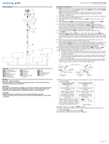
*Remarque: Avec emploi d’un
l paralléle (SPT 1 et SPT 2). Le
l neutre est á angles droits ou
strié et l’autre l doit étre rond
ou lisse (Voir le schéma).
Fil Neutre
13) Enlez la boucle supérieure sur le corps principal.
14) Placer le cache au plafond.
15) Fixer le cache en serrant la bague letée sur le collier-
écrou.
16) Abaissez les stores en verre [N] sur chaque support
comme indiqué. Notez qu’il y a deux (2) tailles de verre
diérentes.
17) Installer les ampoules recommandées (non fournies)
Diagramme d’appareils
ATTENTION – RISQUE DE DÉCHARGES ÉLECTRIQUES -
Couper le courant au niveau du panneau du disjoncteur du
circuit principal ou de la boîte à fusibles principale avant de
procéder à l’installaon.
ATTENTION:
Ce luminaire doit être installé conformément aux codes
d’électricité naonaux (NEC) et sasfaire toutes les
spécicaons des codes locaux. Si vous ne connaissez pas
les exigences de ces codes, il est recommandé de coner
l’installaon à un électricien ceré.
Liste des Pièces
Précauons
[A] L’accouple-
ment
[B] Tige
[C] Tubes letés
[D] Première
boucle
[E] Deuxième
boucle
[F] L’écrou
Hexagonal
[G] Courroie de
Fixation
[H] Boîte de
Sortie
[I] Couvercle/
cache
[J] La chaîne
ouvert
[K] La bague
letée
[L] Vis de xaon
de la courroie
[M] La boucle de
col vissé
Instrucons d’installaon
1) Passer le l de xaon de l’accouplement[A] en haut de
l’appareil à travers une ge [B] et des tubes letés [C] et
visser la ge dans le raccord.
REMARQUE : un frein et doit être appliqué sur tous les
lets de ge tel qu’indiqué par le symbole de la èche
pour éviter toute rotaon accidentelle du luminaire
pendant le neoyage, réinstallaon, etc.
2) Passer le l de xaon à travers la quanté désirée de
Instrucons d’installaon (a connué)
H
G
F
L
N
I
M
K
J
►
D
B
C
►
►
►
A
N
E
/