
IS-43695-US
We’re here to help 866-558-5706
Hrs: M-F 9am to 5pm EST
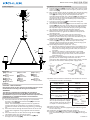
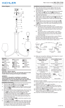
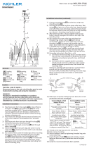
5) Take threaded pipe[A] from parts bag and screw in screw
collar loop[B] a minimum of 6 mm (1/4”). Lock into place
with hexnut[C].
6) Run another hexnut down threaded pipe almost touching
rst hexnut. Now screw threaded pipe into mounng
strap[D]. Mounng strap must be posioned with
extruded thread faced into outlet box[E]. Threaded pipe
must protrude out the back of mounng strap. Screw
third hexnut onto end of threaded pipe protruding from
back of mounng strap.
7) Connect mounng strap[D] to outlet box using the
mounng strap screws[O].
8) Unscrew the threaded ring[F] from screw collar loop. Take
canopy[G] and pass over screw collar loop. Approximately
one half of the screw collar loop exterior threads should
be exposed. Adjust screw collar loop by turning assembly
up or down in mounng strap. Remove canopy.
9) Aer desired posion is found, ghten both top and
boom hexnuts up against the boom and top of the
mounng strap.
10) Slip canopy over screw collar loop and thread on
threaded ring. Aach chain (with xture connected) to
boom of screw collar loop. Unscrew threaded ring, let
canopy and threaded ring slip down.
11) Aach chain link[H] to loop[I] at end of stem and to screw
collar loop[B] on canopy. Close the open chain link by
placing a piece of cloth over the open link and using a pair
of pliers gently squeeze the link closed.
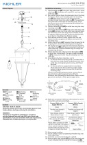
12) Grounding instrucons: (See Illus. a or b).
a) On xtures where mounng strap is provided with a
hole and two raised dimples, wrap ground wire from
outlet box around green ground screw, and thread
into hole.
b) On xtures where a cupped washer is provided,
aach ground wire from outlet box under cupped
washer and green ground screw, then thread into
mounng strap.
If xture is provided with ground wire, connect xture
ground wire to outlet box ground wire with wire
connector aer following the above steps. Never connect
ground wire to black or white power supply wires.
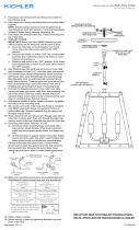
13) Make wire connecon. Reference chart below for correct
connecons and wire accordingly.
Connect Black or Red
Supply Wire to:
Connect White Supply
Wire to:
Black White
*Parallel cord (round &
smooth)
*Parallel cord (square &
ridged)
Clear, Brown, Gold or
Black without Tracer
Clear, Brown, Gold or Black
with Tracer
Insulated wire (other
than green) with copper
conductor
Insulated wire (other
than green) with silver
conductor
*Note: When parallel wire (SPT
1 & SPT 2) are used. The neutral
wire is square shaped or ridged
and the other wire will be round
in shape or smooth (See illus.)
Neutral Wire
14) Raise canopy to ceiling.
15) Secure canopy in place by ghtening threaded ring onto
screw collar loop.
16) Install the recommended bulb (not supplied).
17) Place the glass[M] over the installed bulbs and secure
into place with the glass retainer screws[N], three (3) per
glass.
GREEN GROUND
SCREW
CUPPED
WASHER
OUTLET BOX
GROUND
FIXTURE
GROUND
DIMPLES
WIRE CONNECTOR
OUTLET BOX
GROUND
GREEN GROUND
SCREW
FIXTURE
GROUND
a
b
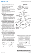
Fixture Diagram
Parts List
[A] Threaded
Pipe
[B] Screw Collar
Loop
[C] Hexnut
[D] Mounting
Strap
[E] Outlet Box
[F] Threaded
Ring
[G] Canopy
[H] Chain Link
[I] Loop
[J] Stem
[K] Threaded
Tubes
[L] Coupling
[M] Glass
[N] Glass
Retainer
Screws
[O] Mounting
Strap Screws
Cauons
CAUTION – RISK OF SHOCK –
Disconnect Power at the main circuit breaker panel or main
fusebox before starng and during the installaon.
WARNING:
This xture is intended for installaon in accordance
with the Naonal Electrical Code (NEC) and all local code
specicaons. If you are not familiar with code requirements,
installaon by a cered electrician is recommended.
Installaon Instrucons
1) Pass xture wire from the coupling on top of xture
through a stem[J] and threaded tubes[K] and screw
stem into coupling[L].
NOTE: Thread locking compound must be applied to
all stem threads as noted with (4) symbol to prevent
accidental rotaon of xture during cleaning, relamping,
etc.
2) Pass xture wire through desired amount of stems and
screw stems together using supplied short threaded
tubes.
3) Pass xture wire from last stem through rst loop[I].
Thread rst loop onto end of last stem.
4) Pass xture wire through screw collar loop[B] and
through hole in canopy[G].
Installaon Instrucons (connued)
E
D
C
O
A
G
B
F
H
►
I
J
K
►
►
►
L
M
N

IS-43695-US
Estamos aquí para ayudarle 866-558-5706
Horario: Lunes-Viernes 9am a 5pm EST (hora ocial del este)
1) Pase el cable del accesorio desde el acoplamiento en la parte
superior del accesorio a través de un vástago[J] y los tubos
roscados[K] y atornille el vástago en el acoplamiento[L].
NOTA: El compuesto de bloqueo de rosca debe aplicarse a
todas las roscas del vástago como se indica con el símbolo
de echa (4) para evitar la rotación accidental del aparato
durante la limpieza, el relamping, etc.
2) Pase el cable del accesorio a través de la candad deseada de
vástagos y atornille los vástagos ulizando los tubos roscados
cortos suministrados.
3) Pase el cable de jación del úlmo vástago a través del primer
bucle[I]. Enhebre el primer bucle en el extremo del úlmo tallo.
4) Pasar el cable de jación a través del ojal del collar roscado[B]
y atravesar el oricio en el escudete[G].
5) Tome el tubo roscado[A] de la bolsa de partes y enrosque
en el ojal del collar roscado[B] un mínimo de 6 mm (1/4”).
Asegúrelo en su lugar con una tuerca hexagonal[C].
6) Coloque otra tuerca hexagonal en el tubo roscado casi
tocando la primera. Ahora enrosque el tubo roscado en la
abrazadera de montaje[D]. La abrazadera de montaje debe
estar colocada con la rosca extruida mirando a la caja de
salida[E]. El tubo roscado debe sobresalir de atrás de la
abrazadera de montaje. Enrosque la tercera tuerca hexagonal
en el extremo del tubo roscado que sobresale de atrás de la
abrazadera de montaje.
7) Conecte la abrazadera de montaje[D] a la caja de salida con
los tornillos de montaje de la correa[O].
8) Desenrosque el anillo roscado[F] del ojal de collar roscado.
Tome el escudete[G] y páselo sobre el ojal de collar roscado.
Aproximadamente la mitad de las roscas externas del ojal de
collar roscado deben ser expuestas. Ajuste el ojal de collar
roscado girando el ensamblaje hacia arriba o hacia abajo en la
abrazadera de montaje. Remueva el escudete.
9) Después de haber encontrado la posición deseada, apriete la
tuerca hexagonal de arriba y de abajo contra la parte inferior
y superior de la abrazadera de montaje.
10) Deslice la escudete sobre el ojal de collar roscado y enrosque
el anillo roscado. Fije la cadena (con el accesorio conectado) a
la parte inferior del ojal de collar roscado. Destornille el anillo
roscado, deje que el escudete y el anillo roscado se deslicen
hacia abajo.
11) Fije el eslabón de la cadena[H] al bucle[I] en el extremo del
vástago y al ojal del collar roscado[B] en el escudete. Cierre el
eslabón de cadena abierto colocando un paño sobre el eslabón
abierto y usando una pinza apriete suavemente hasta cerrarlo.
12) Instrucciones de conexión a erra solamente para los
Estados Unidos. (Vea la ilustracion a o b).
a) En las lámparas que enen el eje, de montaje con un
agujero y dos hoyuelos realzados, enrollar el alambre
a erra de la caja tomacorriente alrededor del tornillo
verde y pasarlo por el aquiero.
b) En las lámparas con una arandela acopada, jar el
alambre a erra de la caja tomacorriente del ajo de la
arandela acoada y tornillo verde, y paser por el eje de
montaje.
Si la lámpara viene con alambre a erra, conecter el alambre a
erra de la lámpara al alambre a erra de la caja
tomacorriente con un conector de alambres espués de seguir
los pasos anteriores. Nunca conectar el alambra a erra a los
alambres eléctros negro o blanco.
13) Haga les conexiones de los alambres. La tabla de referencia
de abajo indica las conexiones correctas y los alambres
correspondientes.
Conectar el alambre de
suministro negro o rojo al
Conectar el alambre de
suministro blanco al
Negro Blanco
*Cordon paralelo (redondo y
liso)
*Cordon paralelo (cuadrado y
estriado)
Claro, marrón, amarillio
o negro sin hebra
idencadora
Claro, marrón, amarillio
o negro con hebra
idencadora
Alambre aislado (diferente
del verde) con conductor de
cobre
Alambre aislado (diferente
del verde) con conductor de
plata
*Nota: Cuando se uliza alambre
paralelo (SPT 1 y SPT 2). El alambre
neutro es de forma cuadrada o
estriada y el otro alambre será
de forma redonda o lisa. (Vea la
ilustracíón). Hilo Neutral
14) Suba el escudete al techo.
15) Asegure el escudete en su lugar apretando el anillo roscado
sobre el ojal de collar roscado.
16) Instale la bombilla recomendada (no suministrada).
17) Coloque el vidrio[M] sobre las bombillas instaladas y
asegúrelo en su lugar con los tornillos de retención de
vidrio[N], tres (3) por vidrio.
ARANDELA
CONCAVA
TIERRA DE LA
CAJA DE SALIDA
TORNILLO DE TIERRA,
VERDE
DEPRESIONES
TIERRA
ARTEFACTO
CONECTOR DE ALAMBRE
TIERRA DE LA
CAJA DE SALIDA
TORNILLO DE TIERRA,
VERDE
TIERRA
ARTEFACTO
a
b
Diagrama de Accesorios
Lista de Partes
Precauciones
PRECAUCIÓN – RIESGO DE DESCARGA ELÉCTRICA –
Desconecte la electricidad en el panel principal del
interruptor automáco o caja principal de fusibles antes de
comenzar y durante la instalación.
ADVERTENCIA:
Este accesorio está desnado a la instalación de
acuerdo con el Naonal Electrical Code (NEC) y todas las
especicaciones del código local. Si no está familiarizado
con los requisitos del código, la instalación se recomienda
un electricista cercado.
Instrucciones de Instalación
Instrucciones de instalación (connuación)
[A] Tubo Roscado
[B] Ojal del Collar
Roscado
[C] Tuerca
Hexagonal
[D] Abrazadera de
Montaje
[E] Caja De Salida
[F] Anillo Roscado
[G] Escudete
[H] Eslabón de
Cadena
[I] Bucle superior
[J] Vástago
[K] Tubos roscados
[L] Acoplamiento
[M] Vidrio
[N] Tornillos de
Retención de
Vidrio
[O] Tornillos de
Montaje de la
Correa
E
D
C
O
A
G
B
F
H
►
I
J
K
►
►
►
L
M
N

IS-43695-CB
We’re here to help 866-558-5706
Hrs: M-F 9am to 5pm EST
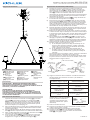
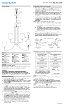
5) Take threaded pipe[A] from parts bag and screw in screw
collar loop[B] a minimum of 6 mm (1/4”). Lock into place
with hexnut[C].
6) Run another hexnut down threaded pipe almost touching
rst hexnut. Now screw threaded pipe into mounng
strap[D]. Mounng strap must be posioned with
extruded thread faced into outlet box[E]. Threaded pipe
must protrude out the back of mounng strap. Screw
third hexnut onto end of threaded pipe protruding from
back of mounng strap.
7) Connect mounng strap[D] to outlet box using the
mounng strap screws[O].
8) Unscrew the threaded ring[F] from screw collar loop. Take
canopy[G] and pass over screw collar loop. Approximately
one half of the screw collar loop exterior threads should
be exposed. Adjust screw collar loop by turning assembly
up or down in mounng strap. Remove canopy.
9) Aer desired posion is found, ghten both top and
boom hexnuts up against the boom and top of the
mounng strap.
10) Slip canopy over screw collar loop and thread on
threaded ring. Aach chain (with xture connected) to
boom of screw collar loop. Unscrew threaded ring, let
canopy and threaded ring slip down.
11) Aach chain link[H] to loop[I] at end of stem and to screw
collar loop[B] on canopy. Close the open chain link by
placing a piece of cloth over the open link and using a pair
of pliers gently squeeze the link closed.
12) Grounding instrucons: (See Illus. a or b).
a) On xtures where mounng strap is provided with a
hole and two raised dimples, wrap ground wire from
outlet box around green ground screw, and thread
into hole.
b) On xtures where a cupped washer is provided,
aach ground wire from outlet box under cupped
washer and green ground screw, then thread into
mounng strap.
If xture is provided with ground wire, connect xture
ground wire to outlet box ground wire with wire
connector aer following the above steps. Never connect
ground wire to black or white power supply wires.
13) Make wire connecon. Reference chart below for correct
connecons and wire accordingly.
Connect Black or Red
Supply Wire to:
Connect White Supply
Wire to:
Black White
*Parallel cord (round &
smooth)
*Parallel cord (square &
ridged)
Clear, Brown, Gold or
Black without Tracer
Clear, Brown, Gold or Black
with Tracer
Insulated wire (other
than green) with copper
conductor
Insulated wire (other
than green) with silver
conductor
*Note: When parallel wire (SPT
1 & SPT 2) are used. The neutral
wire is square shaped or ridged
and the other wire will be round
in shape or smooth (See illus.)
Neutral Wire
14) Raise canopy to ceiling.
15) Secure canopy in place by ghtening threaded ring onto
screw collar loop.
16) Install the recommended bulb (not supplied).
17) Place the glass[M] over the installed bulbs and secure
into place with the glass retainer screws[N], three (3) per
glass.
GREEN GROUND
SCREW
CUPPED
WASHER
OUTLET BOX
GROUND
FIXTURE
GROUND
DIMPLES
WIRE CONNECTOR
OUTLET BOX
GROUND
GREEN GROUND
SCREW
FIXTURE
GROUND
a
b
Fixture Diagram
Parts List
[A] Threaded
Pipe
[B] Screw Collar
Loop
[C] Hexnut
[D] Mounting
Strap
[E] Outlet Box
[F] Threaded
Ring
[G] Canopy
[H] Chain Link
[I] Loop
[J] Stem
[K] Threaded
Tubes
[L] Coupling
[M] Glass
[N] Glass
Retainer
Screws
[O] Mounting
Strap Screws
Cauons
CAUTION – RISK OF SHOCK –
Disconnect Power at the main circuit breaker panel or main
fusebox before starng and during the installaon.
WARNING:
This xture is intended for installaon in accordance
with the Naonal Electrical Code (NEC) and all local code
specicaons. If you are not familiar with code requirements,
installaon by a cered electrician is recommended.
Installaon Instrucons
1) Pass xture wire from the coupling on top of xture
through a stem[J] and threaded tubes[K] and screw
stem into coupling[L].
NOTE: Thread locking compound must be applied to
all stem threads as noted with (4) symbol to prevent
accidental rotaon of xture during cleaning, relamping,
etc.
2) Pass xture wire through desired amount of stems and
screw stems together using supplied short threaded
tubes.
3) Pass xture wire from last stem through rst loop[I].
Thread rst loop onto end of last stem.
4) Pass xture wire through screw collar loop[B] and
through hole in canopy[G].
Installaon Instrucons (connued)
E
D
C
O
A
G
B
F
H
►
I
J
K
►
►
►
L
M
N

IS-43695-CB
Nous sommes là pour vous aider 866-558-5706
Heures : du lundi au vendredi, de 9h à 17h (heure de l’Est)
INSTRUCTIONS:
For Assembling and Installing Fixtures in Canada
Pour L’assemblage et L’installaon Au Canada
Diagramme d’appareils
ATTENTION – RISQUE DE DÉCHARGES ÉLECTRIQUES -
Couper le courant au niveau du panneau du disjoncteur du
circuit principal ou de la boîte à fusibles principale avant de
procéder à l’installaon.
ATTENTION:
Ce luminaire doit être installé conformément aux codes
d’électricité naonaux (NEC) et sasfaire toutes les
spécicaons des codes locaux. Si vous ne connaissez pas
les exigences de ces codes, il est recommandé de coner
l’installaon à un électricien ceré.
Liste des Pièces
Précauons
Instrucons d’installaon
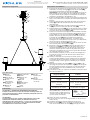
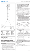
1) Passez le l de xaon du accouplement sur le dessus de
la xaon à travers une ge[J] et des tubes letés[K],
puis vissez la ge dans le accouplement[L].
REMARQUE : un frein et doit être appliqué sur tous les
lets de ge tel qu’indiqué par le symbole de la èche
(4) pour éviter toute rotaon accidentelle du luminaire
pendant le neoyage, réinstallaon, etc.
2) Passer le l de xaon à travers la quanté souhaitée de
ges et la visdérive en ulisant des tubes à letage court
fournis.
3) Passer le l de xaon de la dernière ge à la première
boucle[I]. Enlez la première boucle sur la n de la
dernière ge.
4) Passer le l de xaon à travers le boucle de collier de
vis[B] et le trou traversant dans la cache[G].
5) Prendre leté raccord[A] du sac de pièces et des vis dans
le boucle de collier de vis[B] un minimum de 6 mm (1/4
po). Fixer avec l’écrou hexagonal[C].
6) Couler un autre écrou hexagonal raccord leté touchant
presque le premier écrou hexagonal. Maintenant visser
tuyau leté sur une courroie de xaon[D]. Sangle de
xaon doit être posionné avec l extrudé rencontré
en boîte de sore[E]. Raccord leté doit dépasser
de l’arrière de la sangle de xaon. Troisième écrou
hexagonal sur l’extrémité du raccord à vis qui dépassent
de l’arrière de la sangle de xaon à vis.
7) Fixez la bride de montage[D] à la boîte de sore à l’aide
des vis de xaon de la courroie[O].
8) Dévisser la bague letée[F] du boucle de collier de vis.
Passer le cache[G] sur le boucle de collier de vis. La
moié du letage extérieur du boucle de collier de vis
doit être visible. Ajuster le boucle de collier de vis en
tournant l’ensemble vers le haut ou le bas dans la bride
de montage. Enlever le cache.
9) Une fois bien posionné, serrer les écrous hexagonaux
en haut et en bas contre le dessous et le dessus de la
bride de montage.
10) Glissez la canopée sur la boucle du collier de vis et
vissez la bague letée. Fixez la chaîne (avec le disposif
connecté) au bas de la boucle du collier à vis. Dévisser
la bague letée, laisser glisser le baldaquin et la bague
letée.
11) Aachez le maillon de chaîne[H] à la boucle[I] à la n
de la ge et le boucle de collier de vis[B] sur la canopée.
Fermez le maillon ouvert en plaçant un morceau de ssu
sur le maillon ouvert et à l’aide de pinces, serrez le lien
pour le fermer.
12) Connecter les ls. Se reporter au tableau ci-dessous pour
faire les connexions.
Connecter le l noir ou
rouge de la boite
Connecter le l blanc de
la boîte
A Noir A Blanc
*Au cordon parallèle (rond
et lisse)
*Au cordon parallèle (à
angles droits el strié)
Au transparent, doré,
marron, ou noir sans l
disncf
Au transparent, doré,
marron, ou noir avec un l
disncf
Fil isolé (sauf l vert) avec
conducteur en cuivre
Fil isolé (sauf l vert) avec
conducteur en argent
*Remarque: Avec emploi d’un
l paralléle (SPT 1 et SPT 2). Le
l neutre est á angles droits ou
strié et l’autre l doit étre rond
ou lisse (Voir le schéma).
Fil Neutre
13) Placer le cache au plafond.
14) Fixer le cache en serrant la bague letée sur le boucle de
collier de vis.
15) Installez l’ampoule recommandée (non fournie).
16) Placez le verre[M] sur les ampoules installées et xez
avec les vis de xaon du verre[N], trois (3) par verre.
[A] Fileté
Raccord
[B] Boucle de
Collier de Vis
[C] Écrou
Hexagonal
[D] Courroie de
Fixation
[E] Boîte de
Sortie
[F] Bague Filetée
[G] Cache
[H] Maillon de
Chaîne
[I] Boucle
[J] Tige
[K] Tubes letés
[L] Accouple-
ment
[M] Verre
[N] Vis de
Fixation du
Verre
[O] Vis de
Fixation de la
Courroie
E
D
C
O
A
G
B
F
H
►
I
J
K
►
►
►
L
M
N
-
 1
1
-
 2
2
-
 3
3
-
 4
4


Kichler 43695CH Manuel utilisateur
- Taper
- Manuel utilisateur
- Ce manuel convient également à
dans d''autres langues
- English: Kichler 43695CH User manual
- español: Kichler 43695CH Manual de usuario
Documents connexes
Autres documents
-
 Kichler Lighting 49791AUB Manuel utilisateur
-
 Kichler Lighting 44377BK Manuel utilisateur
-
 Kichler Lighting 44378BK Manuel utilisateur
-
 Kichler Lighting 44284WWW Manuel utilisateur
-
 Kichler Lighting 43534CLP Manuel utilisateur
-
 Kichler Lighting 44315FXG Manuel utilisateur
-
 Kichler Lighting 49236BSL Manuel utilisateur
-
 Kichler Lighting 43519DAG Manuel utilisateur
-
 Kichler Lighting 43234OZ Manuel utilisateur
-
Kichler Lighting 49930WZC Manuel utilisateur


