
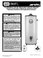
PART NO. 72090 REV. D (07-11)
WARNING:
If the information in these instructions is
not followed exactly, a fire or explosion
may result causing property damage, per-
sonal injury or death.
WARNING:
Improper installation, adjustment, alter-
ation, service, or maintenance can cause
injury or property damage. Refer to this
manual. For assistance or additional infor-
mation, consult a qualified installer, serv-
ice agency, or the gas utility.
FOR YOUR SAFETY
• Do not store or use gasoline or other
flammable vapours and liquids in the
vicinity of this or any other appliance.
• Installation and service must be per-
formed by a qualified installer, service
agency or the gas utility.
• Do not try to light any appliance.
• Do not touch any electrical switch; do
not use any phone in your building.
• Immediately call your gas supplier from
a neighbor’s phone. Follow the gas
supplier’s instructions.
• If you cannot reach your gas supplier,
call the fire department.
WHAT TO DO IF YOU SMELL GAS
GSW Water Heating is a division of
A. O. Smith Enterprises Ltd.
FLAMMABLE VAPOR RESISTANT WATER HEATER
INSTALLATION AND OPERATING INSTRUCTIONS
Read these instructions thoroughly before starting

– 2 –
This page intentionally left blank. May be used for notes or to record other installation information.

– 3 –
TABLE OF CONTENTS
I) INTRODUCTION . . . . . . . . . . . . . . . . . . . . . . . . . . . 4
User Responsibilities 4
II) SAFETY. . . . . . . . . . . . . . . . . . . . . . . . . . . . . . . . . . 4
For Installations in Canada 4
For Installations in the United States 4
Safety Warning (Flammable Vapours) 5
Safety Warning (Scalding) 5
Safety Warning (Carbon Monoxide) 5
Relief Valves (T&P) 5
Backflow Prevention 5
III) INSTALLATION . . . . . . . . . . . . . . . . . . . . . . . . . . . . 6
Unpacking the Water Heater 6
Location Requirements 6
In Earthquake Zones
Clearances and Accessibility 6
Gas Supply 7
Gas Pressure
Gas line purging
Gas Leak Testing
Air Requirements 9
Confined Space Air Requirements for Canadian
Installations 9
Confined Space Air Requirements for U.S.
Installations 10
Exhaust Venting 11
Vent Pipe System
Drafthood Installation
Water Supply 11
Piping Installation
Closed System/Thermal Expansion
Temperature and Pressure (T&P) Relief Valve 12
The Temperature And Pressure Relief Valve:
The Discharge Line:
Installations Check 13
IV) OPERATING INSTRUCTIONS . . . . . . . . . . . . . . . 14
Water Temperature Regulation 14
Temperature Adjustment
Lighting Instructions (Robertshaw 110R) 15
Lighting Instructions (Robertshaw 220R) 16
Lighting Instructions (White-Rodgers 37C) 17
V) OPERATION . . . . . . . . . . . . . . . . . . . . . . . . . . . . . 18
Burner Flames 18
Emergency Shut Down 18
Checking the Draft 18
Operating Conditions 18
Condensation
Water Heater Sounds
Safety Shut-off
Anode/Water Odour
VI) MAINTENANCE . . . . . . . . . . . . . . . . . . . . . . . . . . 19
Draining and Flushing 19
Periodic Inspection 19
External Cleaning of the Flame-arrester 20
Resetting and Replacing the Safety (TCO) Switch20
Temperature and Pressure Relief Valve 20
VII) COMBO HEATING . . . . . . . . . . . . . . . . . . . . . . . . 21
System Requirements 21
VIII) TROUBLESHOOTING GUIDE . . . . . . . . . . . . . . . 22
IX) REPAIR PARTS ILLUSTRATION . . . . . . . . . . . . . 24
LIMITED WARRANTY. . . . . . . . . . . . . . . . . . . . . . 25
RETAIN THESE INSTRUCTIONS IN A SAFE LOCATION FOR FUTURE REFERENCE

I) INTRODUCTION
We thank you for choosing a Flammable Vapor
Resistant Water Heater. Your satisfaction with this product
is very important to us. This gas-fired water heater has been
developed to produce domestic hot water and may also be
used in combination with space heating applications. The
Flame Guard
TM
safety system is designed to reduce the risk
of flammable vapor related fires by trapping the burning
vapors within the water heater combustion chamber using
the special flame arrester. The burning vapors literally “burn
themselves out” without escaping back into the room.
User Responsibilities
These instructions have been written for the proper installa-
tion, safe operation and maintenance of this water heater. It
is your responsibility to ensure that your water heater is
properly installed and cared for.
FAILURE TO FOLLOW THE INSTRUCTIONS IN THIS
MANUAL MAY RESULT IN SERIOUS BODILY INJURY
AND/OR PROPERTY DAMAGE. THOROUGHLY READ
ALL INSTRUCTIONS BEFORE YOU ATTEMPT TO
INSTALL, OPERATE OR MAINTAIN THIS HEATER.
Installation and service requires trade knowledge in the
area of plumbing, electricity, venting, air supply and gas
supply. If you lack these skills or do not understand these
instructions, enlist the help of a qualified professional.
The manufacturer of this water heater cannot be held liable
for those damages caused by improper installation, sizing or
failure to comply with these instructions.
Protect your warranty: Regularly maintain your water
heater and venting system as detailed in the “Maintenance”
section of this manual.
II) SAFETY
This water heater is design-certified by CSA International as
a Category I, non-direct vented water heater which takes its
combustion air either from the installation area or from air
ducted to the unit from the outside.
In addition to the installation instructions found in this man-
ual, the heater shall be installed according to all local and
provincial or state codes or, in the absence of such codes,
with the latest edition of the following specifications.
For Installations in Canada
"Natural Gas and Propane Installation Code" CAN/CSA-
B149.1 and "Canadian Electrical Code (CAN/CSA
C22.1), Part I" available from:
Canadian Standards Association,
5060 Spectrum Way,
Mississauga, Ontario, Canada
L4W 5N6
For Installations in the United States
"National Fuel Gas Code" ANSI Z223.1 (NFPA 54) and
"National Electrical Code" (NFPA 70)" available from:
American National Standards Institute,
25 West 43rd Street,
New York, NY 10036
Massachusetts code requires this water heater to be
installed in accordance with Massachusetts Plumbing and
Fuel Gas Code 248 CMR Section 2.00 and 5.00.
Check your phone listings for the local authorities having
jurisdiction over your installation.
Important: All supply equipment, installation, approvals,
permits, inspections, etc. are the responsibility of the owner
of this water heater. Consult your local authorities for regu-
lations specific to your area.
Your safety and the safety of others is very important.
We have provided many important safety messages in this manual and on your appliance.
Always read and obey all safety messages.
All safety messages will tell you what the potential hazard is, tell you how to reduce the
chance of injury, and tell you what can happen if the instructions are not followed.
This is the safety alert symbol.
This symbol alerts you to potential hazards that can kill or hurt you and others.
All safety messages will follow the safety alert symbol and either the word
“DANGER” or “WARNING”.
DANGER
WARNING
You can be killed or seriously injured if you don’t immediately follow
instructions.
You can be killed or seriously injured if you don’t follow instructions.
WARNING
Service to the Flame Guard
TM
safety system
should only be performed by a qualified
service technician.
– 4 –

Safety Warning (Flammable Vapours)
There is a risk in using fuel-burning appliances such as
water heaters. Areas that may not be suitable for water
heater installation include those where flammable liquids,
gasoline, solvents, adhesives, etc., or engine-driven equip-
ment or vehicles are stored, operated or repaired. Due to
the nature of air movement, flammable vapors can be car-
ried some distance from the point of storage. The gas-fired
water heater igniter or main burner flame can ignite these
vapors causing a flashback, fire or explosion which may
result in serious personal injury or death, as well as severe
property damage.
Safety Warning (Scalding)
Hot water produced by this appliance can cause severe
burns due to scalding. The hazard is increased for young
children, the aged or the disabled where water tempera-
tures exceed 52°C (125°F). Use tempering valves (see
Figure 11), in the hot water system to reduce the risk of
scalding at point-of-use such as lavatories, sinks and
bathing facilities. Such precautions must be followed when
this heater is operated in combination with dishwashing or
space heating applications.
Safety Warning (Carbon Monoxide)
As with all fuel burning equipment, this heater requires an
adequate supply of air for combustion and ventilation. An
insufficient air supply can result in poor combustion or the
re-circulation of the exhaust flue gases. Such a condition
can cause soot build-up or present a fire hazard, and may
result in serious bodily harm or death from asphyxiation.
MAKE SURE THE FLOW OF COMBUSTION AND VENTI-
LATION AIR IS NOT RESTRICTED.
Relief Valves (T&P)
All water heaters must be installed with a proper tempera-
ture and pressure relief valve. These valves must be certi-
fied as meeting the requirements of the “Standard for
Temperature, Pressure, Temperature and Pressure
Relief and Vacuum Relief” CSA 4.4 in Canada. In the
United States “Relief Valves and Automatic Gas Shut-Off
Devices for Hot Water Supply Systems”, ANSI Z21.22 is
applicable.
If this water heater has been exposed to flooding, freezing,
fire or any unusual condition, do not put it into operation until
it has been inspected and approved by a qualified profes-
sional. THESE CONDITIONS CAN RESULT IN UNSEEN
INTERNAL DAMAGE which is not subject to warranty cov-
erage.
Backflow Prevention
Certain jurisdictions may require the installation of a back-
flow device (e.g., check valve) in the water supply line. Such
a device will require the use of a system expansion tank of
adequate size to control the thermal expansion generated
during the heating cycle. Consult your water supplier or
local plumbing authority.
Important: The supply water meter may have a built-in
check valve device. Contact your local water authority.
WARNING
Flammable Vapours
FLAMMABLES
FIRE AND EXPLOSION HAZARD
Can result in serious injury or death
Do not store or use gasoline or other flammable vapours and liquids
in the vicinity of this or any other appliance. Storage of or use of gasoline
or other flammable vapours or liquids in the vicinity of this or any other
appliance can result in serious injury or death.
DANGER
DANGER
Carbon Monoxide Warning
• Follow all vent system requirements by
the local authorities having jurisdiction
over your installation.
• Failure to do so can result in death, explo-
sion or carbon monoxide poisoning.
CAUTION
Hydrogen gas can be produced in a hot water system
served by this heater that has not been used for a long
period of time (generally two (2) weeks or more).
Hydrogen gas is extremely flammable and can ignite
when exposed to a spark or flame. To reduce the risk of
injury under these conditions, it is recommended that the
hot water faucet be opened for several minutes at the
kitchen sink before using any electrical appliance con-
nected to the hot water system. Use caution in opening
faucets. If hydrogen is present, there will probably be an
unusual sound such as air escaping through the pipe as
the water begins to flow. There should be no smoking or
open flame near the faucet at the time it is open.
– 5 –

III) INSTALLATION
Unpacking the Water Heater
Important: Do not remove any permanent instructions,
labels or the rating plate from the outside of the water heater
or on the inside of panels.
1. Move the water heater to the location of installation
before removing the exterior packaging.
2. Remove exterior packaging and place installation com-
ponents aside.
3. Inspect all parts for damage prior to installation and
start-up.
4. Completely read and understand all instructions before
attempting to assemble and install this product.
If you observe damage to the water heater or any of its com-
ponents, DO NOT ASSEMBLE OR INSTALL IT OR MAKE
ANY ATTEMPT TO FIX THE DAMAGED PART(S). Contact
the place of purchase for further instructions.
5. After installation, dispose of packaging material in the
proper manner.
Location Requirements
Note: Before installing this water heater, consideration and
planning must be given to the following details:
•
Location and Clearances.
•
Access for gas supply; See “Gas Supply”.
•
How and where to obtain combustion and ventilation air
supply; See “Air Requirements”.
•
Routing and support of the vent piping.
•
Position of water supply and placement of water piping
for hot and cold water; See “Water Supply”.
•
Floor drain and service.
In Earthquake Zones
Note: The water heater must be braced, anchored, or
strapped to avoid moving during an earthquake. Contact
local utilities for code requirements in your area.
Note: REVIEW SAFETY WARNINGS FOUND IN THE
FRONT OF THIS MANUAL BEFORE PROCEEDING
Clearances and Accessibility
Specific clearance locations are shown in Figure 3. A mini-
mum of 600mm (24 in.) of front clearance shall be provided
for inspection and service. We recommend that 0.9m (36
in.) above be maintained for serviceability.
Locate the water heater such that all controls are easily
accessible.
Clearance to combustibles varies by model. Refer to rating
plate to confirm clearances.
Heaters with a volume of 19 gallons through 50 gallons and
60 gallon (standard input) must have the following minimum
clearances to combustibles:
Front 102mm (4 in.)
Sides and Rear 25mm (1 in.)
Top 203mm (8 in.)
Flue 152mm (6 in.)
JW6058 and G6058 (high input) series heaters must have
the following minimum clearances to combustibles:
Front 127mm (5 in.)
Sides and Rear 25mm (1 in.)
Top 203mm (8 in.)
Flue 152mm (6 in.)
WARNING
Excessive Weight Hazard
Use two or more people to move and install
water heater. Failure to do so can result in
back or other injury.
IMPORTANT:
This water heater must be installed strictly in accordance
with the instructions enclosed, and local electrical, fuel
and building codes. It is possible that connections to the
water heater, or the water heater itself, may develop
leaks. IT IS THEREFORE IMPERATIVE that the water
heater be installed so that any leakage of the tank or relat-
ed water piping is directed to an adequate drain in such a
manner that it cannot damage the building, furniture, floor
covering, adjacent areas, lower floors of the structure or
other property subject to water damage. This is particular-
ly important if the water heater is installed in a multi-story
building, on finished flooring or carpeted surfaces. GSW
WILL NOT ASSUME ANY LIABILITY for damage caused
by water leaking from the water heater, pressure relief
valve, or related fittings. Select a location as centralized
within the piping system as possible. In any location
selected, it is recommended that a suitable drain pan be
installed under the water heater. This pan must limit the
water level to a MAXIMUM depth of 45mm (1 3/4 in.) and
have a diameter that is a minimum of 50mm (2 in.) greater
than the diameter of the water heater. Suitable piping shall
connect the drain pan to a properly operating floor drain.
When used with a fuel-fired heater, this drain pan must not
restrict combustion air flow.
45mm
(1 3/4 in.)
MAX
AT LEAST 50mm (2 in.)
GREATER THAN THE
DIAMETER OF THE
WATER HEATER.
PIPE TO
ADEQUATE
DRAIN
Figure 1 Typical Drain Pan Installation
– 6 –

The 60 gallon heater is equipped with a Heat Reflector
Shield (see Figure 2). This Shield reflects heat from the
High-input heaters to prevent damage to combustible floors.
The Shield is held in place by three (3) tabs that rest on the
inside of the legs of the water heater. Ensure the Shield is
positioned horizontally (parallel to the bottom of the heater)
and in the designated position of 38mm (1.5 in.) below the
flame-arrester.
The water heater shall be located in an area not subject to
freezing temperatures. Water heaters located in uncondi-
tioned spaces (e.g., attics, basements, etc.) may require
insulation of the water and drain piping to protect against
freezing. Proper ventilation needs to be provided for water
heaters installed in unconditioned spaces (e.g., attics, base-
ments, etc.) in order to avoid an event where air tempera-
ture exceeds 42°C (108°F). The drain and controls must be
easily accessible for operation and service. Maintain proper
clearances as specified on the data plate.
Ensure that the water heater is level. This heater may be
installed in a closet or alcove and is certified for operation
on a combustible floor.
Do not locate the water heater near an air-moving device.
The operation of air-moving devices such as exhaust fans,
ventilation systems, clothes dryers, fireplaces, etc., can
affect the proper operation of the water heater. Special
attention must be given to conditions these devices may
create. Flow reversal of flue gases may cause an increase
of carbon monoxide inside of the dwelling, as shown in
Figure 7.
If the water heater is located in an area that is subject to an
excessive amount of lint, dirt or oil, it may be necessary to
clean the flame arrester periodically (see “Maintenance”
section).
Important: It is always recommended that a suitable drain
pan be installed under the water heater to protect the area
from water damage resulting from normal condensation, a
leaking tank or piping connections. Refer to Figure 1. Under
no circumstances is the manufacturer to be held responsi-
ble for any water damage in connection with this water
heater.
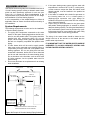
Gas Supply
Install the gas piping as shown in Figure 4. Use only new
pipe and fittings with clean-cut threads. Sealing compounds
used on the pipe threads shall be approved for use with nat-
ural and propane gas.
Use gas piping of adequate sizing to ensure gas input. Gas
piping material must be approved for use with natural gas
and propane fuels. All piping must comply with all local
codes or, in the absence of such codes, with the latest edi-
tion of “Natural Gas and Propane Installation Code”
CAN/CSA-B149.1 in Canada, “National Fuel Gas Code”
ANSI Z223.1 (NFPA 54) in the U.S.A. The final connection
to the water heater is made using 1/2” NPT.
Before connecting to the gas service, check that a properly
sized gas meter and regulator are available to service the
water heater. If other appliances are using the same meter
and regulator, ensure that the capacity of the meter and reg-
ulator matches that of the combined input of all appliances
connected to it.
DO NOT tamper with the gas control/thermostat, igniter,
thermocouple, or temperature and pressure relief valve.
Tampering voids all warranties. Only a qualified service
technician should service these components.
WARNING
Do not install directly on carpet. Instead, place the
water heater on a metal or wood panel extending a
minimum of 75mm (3 in.) from all sides. In alcoves or
closets, cover the carpet completely. Ensure this
panel is capable of supporting the weight of this
heater when filled with water.
FAILURE TO PROPERLY INSTALL THIS HEATER MAY
RESULT IN A FIRE HAZARD.
Figure 3 Minimum Clearance Locations
AIR INTAKE
VENT
FRONT 600mm
(24 in.) MIN.
FOR SERVICE
BACK 25mm (1 in.)
SIDES
25mm
(1 in.)
SIDES AND
BACK 25mm
(1 in.)
TOP TO CEILING
200mm (8 in.)
Figure 2 Heat Shield Installation (60 gallon only)
HEAT SHIELD
FLAME
ARRESTER
DRAIN
VALVE
LEG
BOTTOM
PAN
Figure 4 Recommended Gas Piping
GROUND-
JOINT UNION
MANUAL
GAS
SHUT-OFF
GAS CONTROL/THERMOSTAT
75mm (3 in.)
– 7 –

Gas Pressure
GSW Water Heating Company recommends that the gas
supply pressure, as measured on the inlet side of the water
heater control, be set at 7.0 in. w.c.(1.7 kPa) for natural gas
and 11.0 in. w.c. (2.7 kPa) for propane gas. The above pres-
sures must be measured during water heater operation. The
gas control supplied with this water heater is designed for a
maximum inlet pressure of 0.5 psi (14 in. w.c.). Do not
exceed 0.5 psi (14 in. w.c.). The Flame Guard
TM
safety sys-
tem is designed to operate at a manifold pressure of 5.0 in.
w.c. (1.2 kPa) for natural gas and 10.0 in. w.c. (2.4 kPa) for
propane gas.
Gas line purging
Gas line purging is required to eliminate air from the piping
system. Purging should be performed by persons experi-
enced in this type of gas service in compliance with the
code having jurisdiction. Do not purge in confined areas or
space where ignition may occur. To avoid risk of fire or
explosion ensure the area is well ventilated and all sources
of ignition are de-activated. Contact your local gas authority
for local requirements.
Gas Leak Testing
Important: This water heater and its gas connection must
be tested for leaks before placing the appliance in opera-
tion. Perform a leak test at normal gas pressure. If the appli-
cable code(s) require the gas lines to be tested at a pres-
sure of 14 in. w.c. (3.5 kPa) or greater, the water heater and
its manual shut-off valve must be disconnected from the gas
supply piping system and the line capped. Test all connec-
tions of the gas system with a chloride-free soap and water
solution or equivalent leak test liquid. Bubbles will indicate
leaks. Never use a match or open flame to test for gas
leaks. A fire or explosion could result. If leaks exist repair as
required and retest.
DO NOT light the burner before the tank is filled with water
and you have confirmed that there are no leaks in the pip-
ing and connections.
– 8 –
WARNING
Exposure to a higher gas supply pressure
may cause damage to the control, resulting
in explosion or fire. Consult your local gas
supplier and gas authorities. DO NOT PUT
INTO SERVICE IF OVER-PRESSURIZATION
HAS OCCURRED.

Air Requirements
Important: Air for combustion and ventilation must not
come from a corrosive atmosphere. Any failure due to cor-
rosive elements in the atmosphere is excluded from war-
ranty coverage.
Installations in or for certain places including, but not limited
to, those listed below will require outdoor air for combustion
due to chemical exposure:
Beauty shops
Photo processing labs
Buildings with indoor pools
Water heaters installed in laundry, hobby or craft rooms
Water heaters installed near chemical storage areas
In such circumstances, outdoor combustion air may reduce,
but will not eliminate, the presence of corrosive chemicals in
the air. Combustion air must be free of acid-forming chemi-
cals such as sulfur, fluorine and chlorine. These elements
are found in aerosol sprays, detergents, bleaches, cleaning
solvents, air fresheners, paint and varnish removers, refrig-
erants and many other commercial and household prod-
ucts. When burned, vapors from these products form highly
corrosive acid compounds. These products should not be
stored or used near the water heater or air inlet.
The area in which the heater is located is classified as either
“an unconfined sp
ace
” or “a confined sp
ace
”.
An unconfined sp
ace
is defined as a space having a vol-
ume not less than 50 cubic feet per 1000 BTU/hour (4.8
cubic metres per kilowatt) of combined input rating of all
appliances using the space. Adjacent open rooms may be
included as part of the unconfined space, provided there are
no closeable doors between these rooms. An example of
this is an open basement.
A confined sp
ace is one smaller than described above.
For buildings using tight construction (newer and renovated
structures), the air supply shall be introduced from the out-
doors, regardless of whether the space is confined or
unconfined.
Confined Space Air Requirements for
Canadian Installations
Refer to Figure 5 (a), or (b), and Table 1 for proper sizing
and location of combustion air ducts and openings. CHECK
LOCAL CODES.
(a). Two permanent openings shall be provided connecting
the confined space (e.g., closet, small room) with the
unconfined space. Each opening shall have a free area
of one square inch per 1,000 BTU/hour input (22
cm²/kW) of all appliances in the confined space. The top
opening shall be located as close to the ceiling as prac-
tical but never lower than the top of the heater. (see
Figure 5 (a)). The bottom opening shall be located nei-
ther more than 450mm (18 in.), nor less than 150mm (6
in.), above floor level.
(b). When using a single air supply, the duct shall terminate
within 300mm (12 in.) above and within 600mm (24 in.)
horizontally of the burner level of the appliance having
the largest input. For example: GSW’s water heaters’
burners are 150mm (6 in.) from the floor, plus 300mm
(12 in.) equals 450mm (18 in.) as shown in Figure 5 (b).
All exterior vent openings are to be at least 300mm (12
in.) above the ground and clear of snow levels.
– 9 –
CONFINED
SPACE
PERMANENT
OPENINGS
EQUIPMENT LOCATED IN CONFINED SPACES;
ALL AIR FROM INSIDE THE BUILDING.
(a)
UNCONFINED
SPACE
BASEMENT INSTALLATION, EQUIPMENT LOCATED
IN CONFINED SPACES; ALL AIR FROM OUTDOORS
(b)
CONFINED
SPACE
GRADE
COMBINATION
COMBUSTION/
VENTILATION
AIR DUCT
300mm
(12 in.)
(MIN)
450mm (18 in.)
600mm (24 in.)
Figure 5 Combustion Air Supply Openings And Ducts
(Can.)
BTU / h (kW / hr)
cm
2
in.
2
mm in. mm in.
25,000 8 45 7 76 3 100 4
50,000 15 45 7 76 3 100 4
75,000 23 70 11 100 4 125 5
100,000 30 90 14 100 4 125 5
125,000 37 120 18 125 5 150 6
150,000 45 140 22 125 5 150 6
Acceptable Round
Duct Size Diameter
Combined Input
of All Appliances
in Confined
Space*
Required
Free Area
A**
B***
Table 1 Air Supply Sizing (Can.)
* All appliances refers to, and includes, those appliances
using the same air source (e.g. water heater, furnace,
boiler, clothes dryer etc.).
** Maximum allowable length of ductwork listed in column
A is 6.1 equivalent metres (20 ft.).
*** Maximum allowable length of ductwork listed in column
B is 15.2 equivalent metres (50 ft.)

Confined Space Air Requirements for
U.S. Installations
Refer to Figure 6 (a), (b), (c) or (d) for proper sizing and
location of combustion air ducts and openings. CHECK
LOCAL CODES.
(a) Equipment located in confined spaces; all air from
inside the building.
Two permanent openings shall be provided connecting
the confined space (e.g., closet, small room) with the
unconfined space. Each opening shall have a free area
of one square inch per 1,000 BTU/hour input (22
cm²/kW) of all appliances in the confined space, but not
less than 100 square inches (645 cm²). The top open-
ing shall commence within 300mm (12 in.) of the top of
space and the bottom opening shall commence within
300mm (12 in.) of the bottom of the enclosure.
(b) Basement installation, equipment located in con-
fined spaces; all air from outdoors.
When supplying air directly from the outdoors, each
opening shall have a minimum free area of one square
inch per 4,000 BTU/hour input (5.5 cm²/kW) of total
input rating of all appliances in the confined space. The
inlets shall be a minimum of 300mm (12 in.) above the
grade (snow) line. The top opening shall commence
within 300mm (12 in.) of the top of the confined space.
(c) Equipment located in confined spaces; all air from
outdoors.
When supplying air directly from the outdoors using hor-
izontal ducting, each opening shall have a free mini-
mum area of one square inch per 2,000 BTU/hour (11
cm²/kW) of total input rating of all appliances in the con-
fined space.
(d) Equipment located in confined spaces; all air from
outdoors through ventilated attic.
When supplying air directly through vertical ducting,
each opening shall have a free minimum area of one
square inch per 4,000 BTU/hour (5.5 cm²/kW) of total
input rating of all appliances in the confined space.
CONFINED
SPACE
PERMANENT
OPENINGS
EQUIPMENT LOCATED IN CONFINED SPACES;
ALL AIR FROM INSIDE THE BUILDING.
(a)
UNCONFINED
SPACE
CONFINED
SPACE
ATTIC LOUVERS TO OUTDOORS
EQUIPMENT LOCATED IN CONFINED SPACES; ALL AIR
FROM OUTDOORS THROUGH VENTILATED ATTIC.
(d)
INLET AIR
DUCT
OUTLET
AIR
BASEMENT INSTALLATION, EQUIPMENT LOCATED
IN CONFINED SPACES; ALL AIR FROM OUTDOORS
(b)
CONFINED
SPACE
GRADE
300mm
(12 in.)
300mm
(12 in.)
Figure 6 Combustion Air Supply Openings And Ducts
(U.S.A.)
COMBUSTION
AIR DUCT
PERMANENT
VENTILATION
AIR.
300mm
(12 in.)
ABOVE
GRADE
OR
SNOW
LINE
EQUIPMENT LOCATED IN CONFINED
SPACES; ALL AIR FROM OUTDOORS.
(c)
CONFINED
SPACE
COMBUSTION
300mm (12 in.)
300mm (12 in.)
300mm (12 in.)
OUTDOORS
AIR DUCT
VENTILATION
Burn Hazard
Do not touch vent.
Doing so can result in
burns.
– 10 –

Exhaust Venting
Vent Pipe System
This water heater is a Category 1, non-direct vented appli-
ance.
The vent pipe must be installed in accordance with all local
and provincial or state codes or, in the absence of such
codes, with the latest edition of “Natural Gas and Propane
Installation Code” CAN/CSA-B149.1 in Canada,
“National Fuel Gas Code” ANSI Z223.1 (NFPA 54) in the
U.S.A. The vent pipe must not be obstructed so as to pre-
vent the removal of exhaust gases to the outside atmos-
phere.
Note: The horizontal section of the vent must slope up
21mm per metre (1/4 in. per foot), (see Figure 8).
U.L. recognized fuel gas and carbon monoxide (CO) detec-
tors are recommended in all applications and should be
installed using the manufacturer’s instructions and local
codes, rules or regulations.
Important: If you lack the necessary skills required to prop-
erly install this venting system, you should not proceed, but
enlist the help of a qualified service technician.
Drafthood Installation
Hook the tab leg of the drafthood into the slot in the heater’s
top. Align the remaining legs with the hole/dimples and
secure the drafthood to the top with three screws as shown
in Figure 9. Do not alter the drafthood in any way. If you are
replacing an existing water heater be sure to use the new
drafthood supplied with the water heater.
Water Supply
Piping Installation
Piping, fittings, and valves should be installed according to
the installation drawing (Figure 10). If the indoor installation
area is subject to freezing temperatures, the water piping
must be protected by insulation. Water supply pressure
should not exceed 550 kPa (80psi). If this occurs a pressure
reducing valve and/or an expansion tank may be required.
The pressure reducing valve should be placed on the sup-
ply to the entire house in order to maintain equal hot and
cold water pressures.
Important: Heat must not be applied to the water fittings on
the heater as they may contain nonmetallic parts. If solder
connections are used, solder the pipe to the adapter before
attaching the adapter to the hot and cold water fittings.
Install the water piping and fittings as shown in Figure 10.
Connect the cold water supply to the fitting (3/4” NPT)
marked “COLD” (or “C”). Connect the hot water supply to
the fitting (3/4” NPT) marked “HOT” (or “H”).
REVERSE
FLOW OF
GASES
EXHAUST
FAN
Figure 7 Air Moving Devices
SLOPE UP 21mm PER METRE
(1/4 in. PER ft) MIN.
Figure 8 Vent System
DRAFTHOOD
Figure 9 Drafthood Installation
TAB LEG
SLOT
SCREW
Figure 10 Example Of Water Piping Installation
IN A CLOSED SYSTEM USE EITHER:
1.THERMAL EXPANSION TANK
2.PRESSURE RELIEF VALVE
COLD WATER
INLET VALVE
UNION
PRESSURE REDUCING
VALVE WITH BYPASS
COLD WATER
INLET
TEMPERATURE AND
PRESSURE RELIEF VALVE
DISCHARGE LINE 300mm
(12 in.) MAX (CANADA) OR
150mm (6 in.) MAX (U.S.A.)
ABOVE DRAIN
MASSACHUSETTS:
INSTALL A VACUUM
RELIEF IN COLD WATER
LINE PER SECTION
19MGL 142
DRAIN LINE 19mm
(3/4 in.) ID MIN
HOT WATER
OUTLET
PIPE
INSULATION
– 11 –

Important: Always use a good grade of joint compound,
approved for use with potable water systems, and be certain
that all fittings are drawn up tight.
Important: Some models may contain energy saving heat
traps to prevent the circulation of hot water within the pipes.
Do not remove, modify or tamper with the heat traps or any
inserts within the heat traps.
Please note the following:
DO NOT install this water heater with iron piping. The sys-
tem should be installed only with new piping that is suitable
for potable (drinkable) water such as copper, CPVC or poly-
butylene. DO NOT use PVC water piping.
DO NOT use any pumps, valves or fittings that are not com-
patible with potable water.
DO NOT use valves that may cause excessive restriction to
water flow. Use full flow ball or gate valves only.
DO NOT use any lead based solder in potable water lines.
Use appropriate tin-antimony or other equivalent material.
DO NOT use with piping that has been treated with chro-
mates, boiler seal or other chemicals.
DO NOT add any chemicals to the system piping that will
contaminate the potable water supply.
Closed System/Thermal Expansion
Periodic discharge from the temperature and pressure relief
valve may be due to thermal expansion in a closed water
supply system. The water utility supply meter may contain a
check valve. This will create a closed water system. During
the heating cycle of the water heater, the water expands
causing pressure inside the water heater to increase. This
may cause the temperature and pressure relief valve to dis-
charge small quantities of hot water. To prevent this from
happening, there are two recommendations:
1. Install a diaphragm-type expansion tank that is suitable
for potable water on the cold water supply line. The
expansion tank must have a minimum capacity of 5.7
litres (1.5 US gallons) for every 190 litres (50 US gal-
lons) of stored water and be rated for 150 psi or the
working pressure of the water heater.
2. Install a pressure relief valve rated at max 125 psi in the
cold water supply line. Make sure the discharge of this
valve is directed to an open drain and protected from
freezing. Contact the local water supplier or plumbing
inspector for information on how to control this situation.
Important: Do not plug the temperature and pressure relief
valve.
Temperature and Pressure (T&P) Relief
Valve
Refer to Figure 12 for a typical T&P valve installation.
Important: Only a new temperature and pressure relief
valve should be used with your water heater. Do not use an
old or existing valve as it may be damaged or not adequate
for the working pressure of the new water heater. Do not
place any valve between the relief valve and the tank.
Figure 11 Typical Tempering Valve Installation
TEMPERING
VALVE (SET TO
49°C (120°F))
FOLLOW THE TEMPERING
VALVE MANUFACTURER'S
INSTRUCTIONS
COLD WATER INLET
PIPE
INSULATION
HOT WATER
OUTLET
TEMPERED
WATER TO
FIXTURE
WARNING
Explosion Hazard
• If the temperature and pressure relief
valve is dripping or leaking, have a
licensed plumber repair it.
• Do not plug valve.
• Do not remove valve.
• Failure to follow these instructions can
result in death or an explosion.
Figure 12 Typical Temperature & Pressure Relief Valve
Installation
TEMPERATURE
AND PRESSURE
RELIEF VALVE
DISCHARGE LINE 19mm (3/4 in.)
MIN. DO NOT CAP OR PLUG.
– 12 –

The Temperature And Pressure Relief Valve:
•
Must be connected to an adequate discharge line.
•
Must not be rated higher than the working pressure
shown on the data plate of the water heater.
The Discharge Line:
•
Must not be smaller than the pipe size of the relief valve
or have any reducing coupling installed in the discharge
line.
•
Must not be capped, blocked, plugged or contain any
valve between the relief valve and the end of the dis-
charge line.
•
Must terminate a maximum of 300mm (12 in.) max
(Canada) or 150mm (6 in.) max (U.S.A.) above a floor
drain or external to the building.
•
Must be capable of withstanding 121°C (250°F) without
distortion.
•
Must be installed to allow complete drainage of both the
valve and discharge line.
•
Must not discharge so as to come in contact with any
electrical part or wiring.
Installations Check
Check Here
1. Have the safety precautions described in the
manual been implemented?
2. Does the gas piping conform to the recom-
mendations of your Gas Utility Company?
3. Has the gas piping been tested?
4. Is the supply pressure correct?
5. Is the water heater connected to the correct
gas supply as shown on the rating plate
(Natural Gas/Propane)?
6. Is the clearance between the water heater and
combustible construction as per specifica-
tions?
7. Is the water piping correctly connected? Are
you certain that there are no leaks?
8. Is the water heater filled with water?
9. Is the cold water supply valve open?
10. Is the vent pipe installed properly and are the
vertical and horizontal runs properly support-
ed?
11. Is the vent hood air intake opening unobstruct-
ed?
12. Is the T&P valve installed? Are the drain pipe
and T&P valve unobstructed?
13. Is a drain pan installed with a proper overflow
pipe, directed to a drain?
14. Have you taken steps to prevent water damage
in case of leaks?
15. Does the area around the water heater have
adequate ventilation?
16. Air moving device does not create negative
pressure?
17. Flammable vapors are not placed in the prox-
imity of the water heater?
18. Manifold gasket properly sealed?
19. Viewport not damaged or cracked?
20. Flame-arrester free of debris and undamaged?
21. Two piece grommet properly installed?
22. No leaks at pilot and manifold connection?
23. Manifold door screws securely tightened?
24. Extra care for proper ventilation for attic or
unconditioned space installation (max. air tem-
perature 42°C (108°F))?
– 13 –

IV) OPERATING INSTRUCTIONS
Water Temperature Regulation
HOT WATER CAN SCALD: Water heaters are intended to
produce hot water. Water heated to a temperature that will
satisfy space heating, clothes washing, dish washing, and
other sanitizing needs can scald and permanently injure you
upon contact. Some people are more likely to be perma-
nently injured by hot water than others. These include the
elderly, children, the infirm, or physically/mentally handi-
capped. If anyone using hot water in your home fits into one
of these groups or if there is a provincial, state law or local
code requiring a specific hot water temperature at the tap,
then you must take special precautions. Never allow small
children to use a hot water tap, or to draw their own bath
water. Never leave a child or handicapped person unat-
tended in a bathtub or shower.
It is recommended that lower water temperatures be used
to avoid the risk of scalding. It is further recommended, in all
cases, that the water temperature be set for the lowest tem-
perature that satisfies your hot water needs. This will also
provide the most energy efficient operation of the water
heater.
Temperature Adjustment
The thermostat of this water heater has been factory set at
its lowest position. It is adjustable and must be set to the
desired temperature setting. The preferred starting point is
49°C (120°F). Turn the water temperature dial clockwise
to decrease the temperature, or counterclockwise to
increase the temperature.
Figures 13a & 13b show the approximate water tempera-
tures produced at various thermostat settings. Short repeat-
ed heating cycles caused by small hot water uses can
cause temperatures at the point-of-use to exceed the ther-
mostat setting by up to 17°C (30°F). If you experience this
type of use you should consider using lower temperature
settings to reduce scald hazards. Should overheating occur
or the gas supply fail to shut off, turn off the manual gas con-
trol valve to the appliance.
Valves for reducing the point-of-use temperature by mixing
cold and hot water are available (see Figure 2). Also avail-
able are inexpensive devices that attach to faucets to limit
hot water temperatures. Contact a licensed plumber or the
local plumbing authority.
Note: During low demand periods, a lower thermostat set-
ting will reduce energy losses and may satisfy your normal
hot water needs. If hot water use is expected to be more
than normal, a higher thermostat setting may be required to
meet the increased demand. When leaving your home for
extended periods (e.g., vacations etc.) turn the temperature
dial to its lowest setting. This will maintain the water at low
temperatures with minimum energy losses and prevent the
tank from freezing during cold weather.
GAS CONTROL
KNOB
PILOT
BUTTON
INDEX
BARS
49°C (120°F) BAR
54°C (130°F) BAR
Figure 13a Robertshaw Gas Control/Thermostat Settings
DANGER
Water temperature over 52°C (125°F) can cause
severe burns instantly or death from scalds.
Children, disabled and elderly are at highest risk of
being scalded.
Feel water before bathing or showering.
Temperature limiting valves are available.
WARNING
Risk of scalding
There is a hot water scald potential if the
thermostat is set too high.
Adjusting the thermostat past the 49°C
(120°F) bar on the temperature dial will
increase the risk of scald injury
Hot water can produce third degree burns
in 6 seconds at . . . . . . . .60°C (140°F)
in 30 seconds at . . . . . . .54°C (130°F)
in 5 minutes at . . . . . . . . .49°C (120°F)
GAS CONTROL
KNOB
49°C (120°F) MARK
Figure 13b White-Rodgers Gas Control/Thermostat
Settings
– 14 –

Lighting Instructions (Robertshaw 110R)
FOR YOUR SAFETY READ BEFORE OPERATING
A. This appliance has a pilot which must be lighted by
igniter. When lighting a pilot, follow these instructions
exactly.
B. BEFORE OPERATING smell all around the appliance
area for gas. Be sure to smell next to the floor because
some gas is heavier than air and will settle on the floor.
WHAT TO DO IF YOU SMELL GAS
o
Do not try to light any appliance.
o
Do not touch any electric switch; do not use any
phone in your building.
o
Immediately call your gas supplier from a neighbor’s
phone. Follow the gas supplier’s instructions.
o
If you cannot reach your gas supplier, call the fire depart-
ment.
C. Use only your hand to turn the gas control knob. Never
use tools. If the knob will not turn by hand, don’t try to
repair it, call a qualified service technician. Force or
attempted repair may result in a fire or explosion.
D. Do not use this appliance if any part has been under
water. Immediately call a qualified service technician to
inspect the appliance and to replace any part of the control
system and any gas control which has been under water.
WARNING: If you do not follow these instructions
exactly, a fire or explosion may result causing proper-
ty damage, personal injury or loss of life.
LIGHTING INSTRUCTIONS
1. STOP! Read all safety labels on the water heater before
operation.
2. Remove the outer door.
3. Turn the temperature dial counterclockwise to its low-
est setting.
4. Turn gas control knob clockwise to
the “OFF” position.
5. To clear any gas that may have accu-
mulated wait ten (10) minutes. If you then
smell gas, STOP! Follow instruction “B”described above.
6. Turn the gas control knob counter-
clockwise to “PILOT”.
7. Depress the pilot button all the way in
and IMMEDIATELY depress the igniter
button until you hear loud click. Observe the pilot through
the view port. Do not release the pilot button. Repeat
immediately if pilot does not light on the first try. If the
pilot does not light by the fourth attempt with the igniter,
repeat steps 3-6. Continue to hold the button for about
(1) minute after the pilot is lit. Release the pilot button and
it will pop back up. Pilot should remain lit. If the pilot light
goes out, repeat steps 3-7.
IMPORTANT: If the pilot will not stay lit after several tries,
turn gas control knob to “OFF” and call your service tech-
nician or gas supplier.
IMPORTANT: If the pilot button does not pop up to its
original position when released, stop and immediately
shut off the gas at the line valve or tank. Call your service
technician or gas supplier.
8. Turn the gas control knob counter-
clockwise to “ON”.
9. Set the temperature dial to the desired
setting.
10. Replace the outer door.
ROBERTSHAW 110R
GAS CONTROL
TEMPERATURE DIAL
GAS CONTROL KNOB
IN “PILOT” POSITION
PILOT BUTTON
PILOT
ELECTRODE
THERMOCOUPLE
IGNITER
TO TURN OFF GAS TO APPLIANCE
1. Set the thermostat to lowest setting.
Turn counterclockwise.
2.Turn the gas control knob “OFF”.
Rotate clockwise.
– 15 –

Lighting Instructions (Robertshaw 220R)
FOR YOUR SAFETY READ BEFORE OPERATING
A. This appliance has a pilot which must be lighted by an
igniter. When lighting a pilot, follow these instructions
exactly.
B. BEFORE OPERATING smell all around the appliance
area for gas. Be sure to smell next to the floor because
some gas is heavier than air and will settle on the floor.
WHAT TO DO IF YOU SMELL GAS
o
Do not try to light any appliance.
o
Do not touch any electric switch; do not use any
phone in your building.
o
Immediately call your gas supplier from a neighbor’s
phone. Follow the gas supplier’s instructions.
o
If you cannot reach your gas supplier, call the fire depart-
ment.
C. Use only your hand to turn the gas control knob. Never
use tools. If the knob will not turn by hand, don’t try to
repair it, call a qualified service technician. Force or
attempted repair may result in a fire or explosion.
D. Do not use this appliance if any part has been under
water. Immediately call a qualified service technician to
inspect the appliance and to replace any part of the control
system and any gas control which has been under water.
WARNING: If you do not follow these instructions
exactly, a fire or explosion may result causing proper-
ty damage, personal injury or loss of life.
LIGHTING INSTRUCTIONS
1. STOP! Read all safety labels on the water heater
before operation.
2. Remove the outer door.
3. Turn the temperature dial counterclockwise to its low-
est setting.
4. Turn gas control knob clockwise to the
“OFF” position.
5. To clear any gas that may have accumulated wait
ten (10) minutes. If you then smell gas, STOP!
Follow instruction “B” described above.
6. Turn the gas control knob counterclockwise
to“PILOT”.
7. Depress the gas control knob all the way in and
IMMEDIATELY depress the igniter button until you hear a
loud click. Observe the pilot through the view port. Do not
release the knob. Repeat immediately if pilot does not
light on the first try. If the pilot does not light by the fourth
attempt with the igniter, repeat steps 3-6. Continue to hold
the control knob for about (1) minute after the pilot is lit.
Release the control knob and it will pop back up. Pilot
should remain lit. If the pilot light goes out, repeat steps 3-7.
IMPORTANT: If the pilot will not stay lit after several tries,
turn gas control knob to “OFF” and call your service tech-
nician or gas supplier.
IMPORTANT: If the gas control knob does not pop up to
its original position when released, stop and immediately
shut off the gas at the line valve or tank. Call your service
technician or gas supplier.
8. Turn the gas control knob counterclockwise
to “ON”.
9. Set the temperature dial to the desired setting.
10.Replace the outer door.
TO TURN OFF GAS TO APPLIANCE
1. Set the thermostat to lowest setting.
Turn counterclockwise.
2.Turn the gas control knob “OFF”.
Rotate clockwise.
ROBERTSHAW 220R GAS
CONTROL/
RÉGULATEUR DE GAZ
ROBERTSHAW 220R
GAS CONTROL KNOB
SHOWN IN “OFF” POSITION
PRESSURE REGULATOR
PILOT
THERMOCOUPLE
ELECTRODE
IGNITER
TEMPERATURE DIAL
– 16 –

Lighting Instructions (White-Rodgers 37C)
– 17 –
1. STOP! Read the safety information above on this label.
2. Set the thermostat to lowest setting.
3. This appliance has a pilot that is lit by a spark gas igni-
tion system. Do not try to light the pilot by hand.
4. Remove the outer burner door.
5. Push the gas control knob down slightly and turn clock-
wise to "OFF" (see Figure "A").
NOTE: Knob CANNOT be turned from "PILOT" to "OFF"
unless it is pushed down slightly. Do not force.
6. Wait ten (10) minutes to clear out any gas. Then smell
for gas, including near the floor. If you smell gas, STOP!
Follow “B” in the safety information above on this label.
If you don’t smell gas, go to the next step.
7. Make sure the water heater is filled with water.
8. Turn gas control knob counterclockwise to "PILOT"
(see Figure "A").
9. Depress the gas control knob all the way in and IMME-
DIATELY depress the igniter button until you hear a loud
click. Observe the pilot through the view port. Do not
release the gas control knob. Repeat immediately if pilot
does not light on the first try. If the pilot does not light
by the fourth attempt with the igniter, repeat steps 5-9.
Continue to hold the button for about one (1) minute
after the pilot is lit. Release the gas control knob and it
will pop back up. Pilot should
remain lit. If the pilot light
goes out, repeat steps 5-9.
IMPORTANT: If the pilot will not
stay lit after several tries, turn
gas control knob to "OFF" and
call your service technician or
gas supplier.
IMPORTANT: If the gas control
knob does not pop up to its orig-
inal position when released, stop
and immediately shut off the gas
at the line valve or tank. Call your
service technician or gas suppli-
er.
10.Turn gas control knob
counter-clockwise to "ON"
(see Figure "A").
11. Once the pilot flame is estab-
lished replace the outer burn-
er door.
12.Set thermostat to desired set-
ting.
13.If the pilot will not stay lit after
several tries, turn the gas
control knob clockwise to
"OFF" (see Figure "A"). If the
appliance will not operate, fol-
low the instructions "To Turn
Off Gas To Appliance" and
call a qualified service techni-
cian or gas supplier.
1. Set thermostat to the lowest setting (PILOT LIGHTING).
2. Push the gas control knob down slightly and clock-
wise to the “OFF” position. Do not force.
WARNING: If you do not follow these
instructions exactly, a fire or explo-
sion may result causing property
damage, personal injury or loss of life.
AVERTISSEMENT: Quiconque ne respecte pas à la
lettre les instructions dans la présente notice risque
de déclencher un incendie ou une explosion entraî-
nant des dommages, des blessures ou la mort.
A. This appliance has a pilot that is lit by a piezo-electric
spark gas ignition system. Do not open the inner door
of the appliance and try to light the pilot by hand.
B. BEFORE OPERATING smell all around the appliance
area for gas. Be sure to smell next to the floor because
some gases are heavier than air and will settle on the
floor.
WHAT TO DO IF YOU SMELL GAS
• Do not try to light any appliance.
• Do not touch any electric switch; do not use any phone
in your building.
• Immediately call your gas supplier from a neighbour’s
phone. Follow the gas supplier’s instructions.
• If you cannot reach your gas supplier, call fire depart-
ment.
C. Use only your hand to push in or turn the gas control
knob. Never use tools. If the knob will not push in or
turn by hand, don't try to repair it, call a qualified serv-
ice technician. Force or attempted repair may result in a
fire or explosion.
D. Do not use this appliance if any part has been under
water. Immediately call a qualified service technician to
inspect the appliance and to replace any part of the con-
trol system and any gas control which has been under
water.
A. L'allumage de la veilleuse de cet appareil est assuré par un
système d'allumage piézoélectrique à étincelles. Ne tentez pas
d'ouvrir la porte d'accès interne et d'allumer la veilleuse
manuellement.
B. AVANT DE FAIRE FONCTIONNER, reniflez tout autour de
l'appareil pour déceler une odeur de gaz. Reniflez près du
plancher, car certains gaz sont plus lourds que l'air et peuvent
s'accumuler au niveau du sol.
QUE FAIRE SI VOUS SENTEZ UNE ODEUR DE GAZ:
• Ne pas tenter d'allumer d'appareil.
• Ne touchez à aucun interrupteur; ne pas vous servir des
téléphones se trouvant dans le bâtiment.
• Appelez immédiatement votre fournisseur de gaz depuis un
voisin. Suivez les instructions du fournisseur.
• Si vous ne pouvez rejoindre le fournisseur, appelez le service des
incendies.
C. Ne poussez ou tournez la manette d'admission du gaz qu'à la
main; ne jamais utiliser d'outils. Si la manette reste coincée, ne
tentez pas de la réparer; appelez un technicien qualifié. Le fait de
forcer la manette ou de la réparer peut déclencher une explosion
ou un incendie.
D. N'utilisez pas cet appareil s'il a été plongé dans l'eau, même par-
tiellement. Faites inspecter l'appareil par un technicien qualifié et
remplacez toute partie du système de contrôle et toute
commande qui ont été plongés dans l'eau.
FOR YOUR SAFETY READ BEFORE OPERATING POUR VOTRE SÉCURITÉ LISEZ AVANT DE METTRE EN MARCHE
LIGHTING AND OPERATING INSTRUCTIONS
1. ARRÊTEZ! Lisez les instructions de sécurité sur la portion
supérieure de cette étiquette.
2. Réglez le thermostat à la température la plus basse.
3. L'allumage de la veilleuse de cet appareil est assuré par un
système d'allumage à étincelles. Ne tentez pas d'allumer la
veilleuse manuellement.
4. Enlevez la porte d'accès externe.
5. Appuyez sur le bouton de commande du gaz et faites-le tourner
dans le sens horaire jusqu'à "OFF" (Figure A).
NOTE: Il n'est PAS POSSIBLE de faire passer le bouton de "PILOT"
à "OFF" à moins d'appuyer dessus. Ne le forcez pas.
6. Attendre dix (10) minutes pour laisser échapper tout le gaz.
Reniflez tout autour de l'appareil, y compris près du plancher,
pour déceler une odeur de gaz. Si vous sentez une odeur de gaz,
ARRÊTEZ! Passez à l'étape "B" des instructions de sécurité sur
la portion supérieure de cette étiquette. S'il n'y a pas d'odeur de
gaz, passez à l'étape suivante.
7. Assurez-vous que le chauffe-eau est complètement rempli d'eau.
8. Faites tourner le bouton de commande du gaz dans le sens anti-
horaire jusqu'à "PILOT" (Figure A).
9. Enfoncez complètement le bouton de commande du gaz et
appuyez IMMÉDIATEMENT sur le bouton de l'allumeur jusqu'à ce
que vous entendiez un bon déclic. Observez la veilleuse par le
regard de la chambre de combustion. Ne relâchez pas le bouton
de commande du gaz. Répétez immédiatement la
manœuvre si la veilleuse ne s'allume pas dès la pre-
mière tentative. Si la veilleuse refuse toujours de
s'allumer à la quatrième tentative avec l'allumeur,
répétez les étapes 5 à 9 inclusivement. Continuez d'ap-
puyer sur le bouton de commande du gaz pendant
environ une (1) minute après l'allumage de la veilleuse.
Relâchez le bouton de commande du gaz et il
retournera à sa position initiale. La veilleuse devrait
rester allumée. Si la veilleuse s'éteint, répétez les
étapes 5 à 9 inclusivement.
IMPORTANT: Si la veilleuse ne reste pas allumée après
plusieurs tentatives, tournez le bouton de commande
du gaz jusqu'à "OFF" et appelez un technicien qualifié
ou votre fournisseur du gaz.
IMPORTANT: Si le bouton de commande du gaz ne
retourne pas à sa position initiale lorsque vous le
relâchez, arrêtez et fermez immédiatement le gaz au
régulateur principal ou au réservoir. Appelez un techni-
cien qualifié ou votre fournisseur du gaz.
10. Faites tourner le bouton de commande du gaz dans
le sens antihoraire jusqu'à "ON" (Figure A).
11. Une fois la veilleuse allumée, remettez en place la
porte d'accès externe.
12. Réglez le thermostat à la température désignée.
13. Si la veilleuse ne reste pas allumée après plusieurs
tentatives, faites tourner le bouton de commande
du gaz dans le sens horaire jusqu'à "OFF" (Figure
A). Si l'appareil ne se met pas en marche, suivez les
instructions intitulées "Comment couper
l'admission des gaz de l'appareil" et appelez un
technicien qualifié ou le fournisseur de gaz.
DIRECTIVES D'ALLUMAGE ET DE MISE EN MARCHE
TO TURN OFF GAS TO APPLIANCE
1. Réglez le thermostat à la température la plus basse (ALLUMAGE
DE LA VEILLEUSE).
2. Appuyez sur le bouton de commande du gaz et faites-le tourner
dans le sens horaire jusqu'à "OFF". Ne le forcez pas.
71731
COMMENT COUPER L'ADMISSION DES GAZ DE L'APPAREIL
Figure A
“OFF” Position “fermé”
Gas Control Knob
Bouton de commande
du gaz
Igniter
Button
Bouton de
l’allumeur
Thermostat Dial
Cadran de réglage du thermostat
Gas Control - Commande du gaz
ELECTRODE
THERMO-
COUPLE
PILOT
Veilleuse
Gas Control Knob
Top View
Vue en plongée

V) OPERATION
Burner Flames
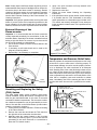
Inspect the burner flames through the viewport and com-
pare them to the drawings in Figure 14. A properly operat-
ing burner should produce a soft blue flame. Blue tips with
yellow inner cones are satisfactory. The tips of the flame
may have a slight yellow tint. The flame should not be all
yellow or have a sharp blue-orange color. Contaminated air
may cause an orange colored flame. Contact a qualified
service technician if the flame is not satisfactory.
Emergency Shut Down
Important: Should overheating occur or the gas supply fail
to shut off, turn off the water heater’s manual gas shut-off
valve and call a qualified service technician.
Checking the Draft
After successfully lighting the water heater, allow the unit to
operate for 15 minutes and check the drafthood relief open-
ing for proper draft. Pass a match flame around the relief
opening of the drafthood as shown in Figure 15. A steady
flame drawn into the opening indicates proper draft. If the
flame flutters or is blown out, combustion products are
escaping from the relief opening. If this occurs, do not oper-
ate the water heater until proper adjustments or repairs are
made to the vent pipe system.
Operating Conditions
Condensation
Moisture from the products of combustion condenses on the
tank surface and forms drops of water which may fall onto
the burner or other hot surfaces. This will produce a “siz-
zling” or “frying” noise. This condensation is normal and
should not be confused with a leaking tank. Condensation
may increase or decrease at different times of the year.
Highly efficient energy saver water heaters will produce
larger amounts of condensation on initial start up or when a
large amount of hot water is being used. Once the water
reaches a temperature of 49°C (120°F) and the tank warms
up (usually about 1 hour), the condensation will stop.
Note: At initial start-up, in certain extremely cold conditions
and if the water heater is not allowed enough time to reach
the room temperature, the pilot burner might be extin-
guished in the first 20 minutes from start-up due to heavy
condensation. In this situation if the unit is relit, it will follow
its normal heating cycle without further incidents. After
installation always allow the water heater to reach the room
temperature before the initial start-up is initiated. Supervise
the flame inside the water heater at least 20 minutes at ini-
tial start-up to ensure that heavy condensation is not turning
off the water heater.
Water Heater Sounds
During the normal operation of the water heater, sounds or
noises may be heard. These noises are common and may
result from the following:
•
Normal expansion and contraction of metal parts during
the periods of heat-up and cool-down.
•
Condensation causing sizzling and popping within the
burner area.
•
Sediment build up in the tank bottom creating varying
amounts of noise. Build up may cause premature tank
failure. Drain and flush the tank as directed under
“Draining and Flushing”.
Safety Shut-off
This water heater is designed to automatically shut-off in the
event of the following:
•
The pilot flame is extinguished for any reason.
•
The water temperature exceeds 93°C (200°F).
•
Excessive combustion chamber temperatures.
•
The ignition of flammable vapors.
A thermocouple is used to determine if a pilot flame is pres-
ent and will shut off the gas supply to the main burner and
the pilot burner if the flame is absent.
A dual safety switch is part of the water heater safety sys-
tem. The gas control is connected to a door-mount manual
ly resettable safety switch which is designed to disable the
gas control/thermostat in the event of excessive combustion
chamber temperatures or a flammable vapor incident. If the
thermal switch opens, the water heater cannot be used
unless this thermal switch is reset by a qualified service
technician.
The gas control has a high temperature limit switch or ECO
(Energy Cut Off) which is used to shut off the unit if the
water temperature exceeds 93°C (200°F). The ECO is a
single use switch and requires complete replacement of the
entire gas control/thermostat. If the ECO should function,
the water heater cannot be used until the gas control/ther-
mostat is replaced by a qualified service technician. Contact
your local dealer for service information.
Anode/Water Odour
Each water heater contains at least one anode, which will
slowly deplete while protecting the glass-lined tank prolong-
ing the life of the water heater. Certain water conditions may
cause a reaction between the anode and the water. The
most common complaint associated with the anode is a “rot-
ten egg smell” produced by the presence of sulfur. Do not
remove this anode permanently as it will void any war-
ranties, stated or implied. An aluminum anode may reduce
CORRECT FLAME
SOFT BLUE
INCORRECT
FLAME LAZY
YELLOW
Figure 14 Flame Characteristics
TIPS MAY HAVE
A YELLOW TINT
YELLOW INNER
CONES ARE
SATISFACTORY
Figure 15 Checking The Draft
MATCH
RELIEF
OPENING
– 18 –

if not eliminate water odour problems. The water supply sys-
tem may require special filtration equipment from a water
conditioning company to successfully eliminate all water
odour problems.
Artificially softened water is exceedingly corrosive because
the process substitutes sodium ions for magnesium and cal-
cium ions. The use of a water softener may decrease the life
of the water heater tank. The anode should be inspected
periodically. If the anode is more than 50% depleted, the
anode should be replaced.
VI) MAINTENANCE
Draining and Flushing
It is recommended that the tank be drained and flushed
every 6 months to remove sediment which may buildup dur-
ing operation. The water heater should be drained if being
shut down for extended periods of time. To drain the tank,
perform the following steps:
1. Turn off the gas to the water heater with the manual gas
shut-off valve.
2. Close the cold water inlet valve.
3. Open a nearby hot water faucet.
4. Connect a hose to the drain valve and terminate it to an
adequate drain.
Note: The drain hose should be rated for at least 94°C
(200°F). If the drain hose does not have this rating, open the
cold water inlet valve and nearby hot faucet until the water
is no longer hot.
5. Open the water heater drain valve and allow all the
water to drain from the tank. Flush the tank with water
as needed to remove sediment.
6. Close the drain valve, refill the tank, and restart the
heater as directed under “Operating Instructions”. If the
water heater is going to be shut down for an extended
period, the drain valve should be left open.
Important: Condensation may occur when refilling tank and
should not be confused with a tank leak.
The installation and maintenance of the water heater must
comply with all of the instructions described in sections I to
IX of this manual. Water heater failure that is a result of the
heating system is not covered by warranty.
The following maintenance procedures are for the Flame
Guard
TM
safety system components and should be per-
formed by a qualified service technician.
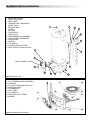
Replacement parts (see Figures 20 & 21) may be ordered
through your local distributor. When ordering replacement
parts, always have the following information ready:
1. Model, serial and product number.
2. Type of gas.
3. Item number.
4. Parts description.
Periodic Inspection
Periodically a visual inspection should be made of the vent-
ing and air supply system, piping systems, main burner,
pilot burner and flame arrester.
Check the water heater for the following:
1. Obstructions, damage or deterioration in the venting
system. Make sure the ventilation and combustion air
supplies are not obstructed.
2. Build-up of soot and carbon on the main burner and
pilot burner. Check for a soft blue flame.
3. Leaking or damaged water and gas piping.
4. Presence of flammable or corrosive materials in the
installation area.
5. Presence of combustible materials near the water
heater.
6. Presence of debris on the outside of the flame arrester.
See note below.
– 19 –

Note: Visually inspect the flame arrester by placing a mirror
underneath the water heater. A flashlight can be used to illu-
minate the slots in the flame arrester if necessary. Routine
cleaning of the flame arrester is recommended if inspection
shows accumulation of debris on the flame arrester. See
section titled “External Cleaning of the Flame-arrester” for
cleaning instructions.
Important: Verify proper operation after servicing this water
heater. If you are unsure of this inspection procedure or the
proper operation of the water heater and its special safety
features, enlist the services of a qualified service technician.
External Cleaning of the
Flame-arrester
Important: It is recommended that the flame arrester be
visually inspected periodically for accumulation of dust, lint
and other debris, especially if the heater is installed in areas
having a high dust and/or lint content. Any such accumula-
tion should be cleaned as outlined below.
1. Use a vacuum cleaner to remove all loose debris in the
flame arrester.
2. If necessary, a soft bristle brush can be used to dis-
lodge any remaining debris.
3. Repeat step 1 as necessary to completion.
Resetting and Replacing the Safety
(TCO) Switch
The water heater safety system includes a door-mount,
manual resettable, safety switch which is designed to dis-
able the gas control/thermostat in the event of excessive
combustion chamber temperatures. The excessive combus-
tion chamber temperatures may be generated by accumu-
lation of lint and dust on the flame-arrester (located under-
neath the combustion chamber),
1. Follow first the procedure outlined in "External Cleaning
of the Flame-arrester".
2. Remove the outer door and locate the TCO switch on
the right side of the combustion chamber door.
3. Manually press the contact located on the front-right
side of the TCO switch (Figure 17) until a click sound is
generated. Do not use a metal tool or a screwdriver to
press the TCO switch contact.
4. Verify if the quick connects are firmly inserted in the
TCO switch contacts.
5. Replace the outer door.
6. Restart the water heater following the “Operating
Instructions”.
7. If the pilot burner does not stay lit after several attempts
it is possible that the TCO embedded in the safety
switch opened due to a flammable vapor incident or the
TCO switch was severely damaged. Do not attempt to
further operate the water heater. Call a qualified service
technician.
Temperature and Pressure Relief Valve
Manually operate the temperature and pressure relief valve
at least once a year to make sure it is working properly. To
prevent water damage, the valve must be properly connect-
ed to a discharge line which terminates at an adequate
drain. Standing clear of the outlet (discharged water may be
hot), slowly lift and release the lever handle on the temper-
ature and pressure relief valve (see Figure 18) to allow the
valve to operate freely and return to its closed position. If the
valve fails to completely reset and continues to release
water, immediately shut off the manual gas shut-off valve
and the cold water inlet and call a qualified service techni-
cian.
Figure 17 TCO Switch
TCO
RESET
CONTACT
THERMAL
LINK
Figure 18 T&P Relief Valve Test
TEMPERATURE AND
PRESSURE RELIEF VALVE
MANUAL RELIEF VALVE
DISCHARGE LINE TO DRAIN
Figure 16 Flame Arrester (External View)
FLAME
ARRESTER
– 20 –
La page est en cours de chargement...
La page est en cours de chargement...
La page est en cours de chargement...
La page est en cours de chargement...
La page est en cours de chargement...
La page est en cours de chargement...
-
 1
1
-
 2
2
-
 3
3
-
 4
4
-
 5
5
-
 6
6
-
 7
7
-
 8
8
-
 9
9
-
 10
10
-
 11
11
-
 12
12
-
 13
13
-
 14
14
-
 15
15
-
 16
16
-
 17
17
-
 18
18
-
 19
19
-
 20
20
-
 21
21
-
 22
22
-
 23
23
-
 24
24
-
 25
25
-
 26
26


dans d''autres langues
- English: GSW 72090 User manual
Documents connexes
Autres documents
-
Rheem XP75T12UHN100U0 Mode d'emploi
-
-
State Water Heaters GP650YTVIT Manuel utilisateur
-
HTP Everlast Electric Mini Tank Water Heater Manuel utilisateur
-
State SGV-82-10TS , SGV-120-10TS Manuel utilisateur
-
Mr. Heater F272200 Manuel utilisateur
-
Ariston ANDRIS RS 2.5U 1.4KW Manuel utilisateur
-
A.O. Smith 100119516 Guide d'installation
-
Bosch Appliances WR430-7K Manuel utilisateur
-