Posiflex HS-6710W/6712W/6714W Manuel utilisateur
- Taper
- Manuel utilisateur

1
Package Contents
HS-67xxW desktop POS (x 1)
24V/100W Power Adaptor (x 1)
Power cord (x 1)
3-inch wide thermal paper roll (x 1)
Paper separator for 2” thermal paper roll (x 1)
Desktop mounting kit pack for HS-6710W (x 1)
(including 1 desktop mounting bracket,
4 fixing screws, and 4 plastic anchors)
Desktop mounting kit pack for HS-6714W (x 1)
(including 1 bottom plate, 1 desktop mounting
bracket, 4 fixing screws, and 4 plastic anchors)
User manual (x 1)
SOME IMPORTANT NOTES
FCC NOTES
This equipment has been tested and found to comply with the limits for a Class A
digital device, pursuant to part 15 of the FCC Rules. These limits are designed to
provide reasonable protection against harmful interference when the equipment is
operated in a commercial environment. This equipment generates, uses, and can radiate
radio frequency energy and, if not installed and used in accordance with the instruction
manual, may cause harmful interference to radio communications. Operation of this
equipment in a residential area is likely to cause harmful interference in which case the
user will be required to correct the interference at his own expense.
This device complies with part 15 of the FCC Rules. Operation is subject to the
following two conditions: (1) This device may not cause harmful interference, and (2)
this device must accept any interference received, including interference that may cause
undesired operation.
CE CLASS A WARNING
This equipment is compliant with Class A of CISPR 32. In a residential environment
this equipment may cause radio interference.
15651900010 Ver. A0
http://www.posiflex.com
HS-6710W/6712W/6714W
Desktop POS
User Manual

2
AVERTISSEMENT CE CLASSE A
Cet équipement est conforme à la classe A de CISPR 32. Dans un environnement
résidentiel, cet équipement peut provoquer des interférences radio.
WARRANTY LIMITS
Warranty will terminate automatically when the machine is opened by any person other
than the authorized technicians. The user should consult his/her dealer for the problem
happening. Warranty voids if the user does not follow the instructions in application of
this merchandise. The manufacturer is by no means responsible for any damage or
hazard caused by improper application.
LIMITES DE GARANTIE
La garantie prend fin automatiquement lorsque la machine est ouverte par une personne
autre que les techniciens autorisés. L'utilisateur doit consulter son revendeur pour le
problème qui se produit. La garantie s'annule si l'utilisateur ne suit pas les instructions
d'application de cette marchandise. Le fabricant n'est en aucun cas responsable de tout
dommage ou danger causé par une mauvaise application.
警告
為避免電磁干擾,本產品不應安裝或使用於住宅環境。
SAFETY INSTRUCTIONS
This equipment is not suitable for use in locations where children are likely to be
present.
CONSIGNES DE SÉCURITÉ
Cet équipement ne convient pas à une utilisation dans des lieux pouvant accueillir des
enfants.
WARNING
Power cord shall be connected to a socket-outlet with earthing connection
ATTENTION
Le cordon d'alimentation doit être connecté à une prise de courant avec mise à la terre.
BATTERY WARNING
Risk of explosion if battery is replaced by an incorrect type. Dispose of expended battery in
accordance with local disposal regulations.
AVERTISSEMENT DE BATTERIE
Risque d'explosion si la batterie est remplacée par un type incorrect. Jetez la batterie
usagée conformément aux réglementations locales en matière d'élimination.
警告
本電池如果更換不正確會有爆炸的危險,請依製造商說明書處理用過之電池。

3
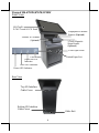
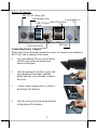
Cable Exit
Views of HS-6710W/6712W/6714W
Front View
Rear View
3-Track Magnetic
Stripe Reader
(Optional)
Printed Paper Exit
HS-67xxW
P-CAP Touch & LCD Panel
Fingerprint or iButton
Sensors (Optional)
Posiflex 2D Scanner
(Optional)
Top I/O Interface
Cable Cover
Bottom I/O Interface
Cable Cover
Cover Open Lever
Power LED Indicator
Error LED Indicator
Paper-out LED
Indicator
Feed Button

4
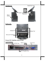
Left Side View Right Side View
Bottom View
Views of I/O Interface of HS-67xxW
Top I/O Interface
Bottom I/O Interface
Rubber Pad
Rubber Pad
Mounting holes
RFID Card Reader
(Optional)
Power
Button
DB-25 Parallel Port
RJ-50 COM Port
USB 3.0 Port
VGA Port

5
Bottom I/O Interface
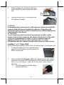
Connecting Power Adapter
Please refer to the following instructions on how to connect power adapter to
HS-67xxW and to organize your cables.
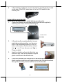
1. Lay your desktop POS on a level surface
with its touch screen facing down as
shown in the figure.
2. Hold the bottom I/O interface cover with
your thumb and forefinger, and then
gently pull the cover outwards to remove
the cover.
3. Connect power adapter and I/O cables to
the bottom I/O interface.
4. Have the cover join to the wedge portions
of the bottom I/O interface.
DB-9 COM Ports
PS/2 Port
Cash Drawer Port
24V DC-IN Power Jack
RJ-45 LAN Port
USB 3.0 Ports
Line Out/Mic in

6
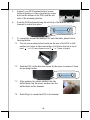
5. Before pushing the cover back into place,
neatly thread the cables through the cable
exit.
6. Press down the cover to close the bottom
I/O interface chamber.
CAUTION:
On doing insertion or extraction of a cable connector, please always hold the
connector head itself instead of pulling the cable wire. Doing this could
damage the cables and ports, which is considered as an artificial damage and
is not covered by the warranty.
ATTENTION:
Lors de l'insertion ou de l'extraction d'un connecteur de câble, veuillez
toujours tenir la tête du connecteur elle-même au lieu de tirer le fil du câble.
Cela pourrait endommager les câbles, ce qui est considéré comme un
dommage artificiel et n'est pas couvert par la garantie. Le cordon
d'alimentation doit être connecté à une prise de courant avec mise à la terre.
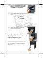
Loading 2” or 3” Paper Rolls
Before operating the printer, please follow the below steps to load a paper roll.
1. To open the paper roll cover, push down the
paper roll cover release lever in the direction
shown in the figure.
2. Before installing 2-inch paper roll in the thermal printer, place paper
separator in the paper roll compartment by following the instructions
below. If you are using 3” paper roll for the printer, please skip to
next step.
2.1. Hold the separator with the sharp-
pointed side down.
Cable Exit

7
2.2. Push the sharp-pointed part of paper
separator into the slot on the bottom
of the paper roll compartment.
2.3. Put the paper separator into the slot as shown in the below
figure.
2.4. Drop 2-inch paper roll inside the
paper roll compartment.
3. To load the thermal printer with the 3-inch
paper roll, just drop the thermal paper roll
inside the paper roll compartment of the
printer as illustrated in the figure.
4. Unroll the thermal paper and drag the loose
end of the paper till it extends towards the
paper cutter.

8
5. Make sure the loose end sticks out of the
opening of the paper roll compartment. Then,
close the paper roll cover by pushing it back
at the center of the top side of the cover with
a click sound.
To avoid paper jam or other printing errors, do NOT
press the paper roll cover release lever during printing.
Mounting the POS onto a Table
This section will describe two alternative solutions to help you fix the POS
firmly onto a table in preventing your POS system from being rocked, tipped
or tilted accidentally.
Using bottom plate
Please follow the steps below to install the bottom plate for HS-6714W.
1. Take the bottom plate with the mounting bracket out of the package,
and place it with its screw holes on the top in your preferred position.
2. Support your POS terminal with its
screen facing towards you. Then, align
the two screw bolts on the bottom of the
POS with the rail slots of the mounting
bracket.
3. Push the POS backwards along the rail slots of the bracket until the
terminal is locked into place.
Bottom Plate
Mounting bracket
Screw holes

9
4. After inserting another two scerws into the two mouting holes located
on the rear of the POS, fasten them to fix the POS termial to the
bottom plate.
Using desktop-mounting kits
Please follow the steps below to install desktop-mounting kits.
1. Please first release the mounting bracket from the bottom plate by
removing two screws as shown in the figure.
2. After placing the mounting bracket in your
preferred mounting position, use the screw
holes of the mounting bracket to drill two
holes on the surface. Each hole has to be at
least
4
1
” or 6.25 mm diameter and
8
3
1
” or
35mm in depth.
3. Insert two plastic anchors into the holes you
drilled in step 2 and use a hammer to tap the
plastic anchors into the drilled holes.
4. After well attaching two screw holes of the mounting bracket to the
plastic anchors, insert two self-tapping screws into the plastic anchors
through the mounting bracket and then secure the bracket.
Mounting bracket
Bottom Plate

10
5. Support your POS terminal with its screen
facing towards you. then, align the two screw
bolts on the bottom of the POS with the rail
slots of the mounting bracket.
6. Push the POS backward along the rail slots of the bracket until the
terminal is locked into place.
7. To completely mount the desktop POS onto the table, please follow
the steps below.
7.1 Use the two mouting holes located on the rear of the POS to drill
another two holes on the same surface. Each hole also has to be at
least
4
1
” or 6.25 mm diameter and
8
3
1
” or 35mm in depth.
7.2 Push the POS in the direction shown by the arrow to reomve it from
the mouting bracket.
7.3 After pushing two plastic anchors into the
drilled holes, tap the plastic anchors into the
drilled holes with a hammer.
7.4 Refer Step 6 to mount the POS to the bracket.

11
7.5 Apply two self-tapping screws through the mounting holes into the
two plastic anchors. Then, fasten the screws to completely lock the
POS onto the table.
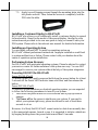
Installing a Customer Display to HS-67xxW
HS-67xxW also allows you to additionally install a customer display to expand
its functionality. Based on the model of the second display, the step-by-step
instructions are provided in its own user guide to help you mount it onto your
POS system. Please refer to the relevant user manual for detailed information.
Installing an Operating System
You are highly advised NOT to install an operating system on
HS-67xxW without professional instructions. Improper installation could lead
to system malfunction or failure. Please contact with your dealers about the
issues of operation system installation.
Performing System Recovery
For HS-67xxW with preloaded operating systems, Please be advised to contact
your service center for further assistance with system recovery. You are NOT
encouraged to recover your system without the help of the system integrators.
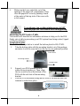
Powering ON/OFF the HS-67xxW
Power ON HS-67xxW
To power on the POS, gently press and hold down the power button for at least
3 seconds till the Power LED indicator turns solid blue, and then release the
button.
Power OFF HS-67xxW
To initiate a system shutdown on Android operating system, you are expected
to follow the following procedures to turn off your system:
1. Press down the power button for a few seconds until a pop-up window
appears.
2. Tap Power off on the screen to shut down your system. If you need to
reboot your system right away, please be advised to wait at least three
seconds to do so.
However, it is likely that HS-67xxW cannot restart or shut down normally due
to the unexpected reasons. In such a case, it is suggested to initiate a shutdown
by keeping holding down the power button more than 10 seconds.

12
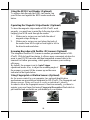
Using the RFID Card Reader (Optional)
To retrieve data through the RFID card reader, tap
your Mifare card against the RFID reader as shown
below.
Operating the Magnetic Stripe Reader (Optional)
To have the magnetic stripe reader of HS-67xxW work
properly, you must bear in mind the following tips while
swiping your MSR cards through the reader.
1. Make sure to swipe your card with the side of
magnetic stripe facing up.
2. Make sure to swipe your card along the track of
the reader from left to right or from right to left in
the direction shown below.
Scanning Barcodes with Posilfex 2D Scanner (Optional)
The integrated Posiflex 2D Scanner is another prominent feature of HS-
67xxW. With its hand-free design, it offers a more convenient solution for
users to read 1D/2D barcodes and then transmitted scanned data to the
terminal for further processing, which greatly increases your working
efficiency.
By default, the scanner is set to Auto Trigger
operational mode. Also, to adjust the scanning angle of
the scanner, you may tilt the scanner up and down as
indicated in the figure below.
Using Fingerprint or iButton Sensors (Optional)
As for access control to your computer, two optional identification
mechanisms are provided and integrated in HS-67xxW: The fingerprint and
iButton sensors. Either will work to verify an individual’s identity.
In order to allow the fingerprint sensor to function normally, you have to
register your own finger first using Fingerprint Recognition Tool which is
pre-installed and accessible on your desktop of your system.
Fingerprint Sensor
iButton Sensor

13
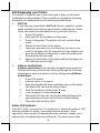
Self-Diagnosing your Printer
The variety of diagnostic tips is provided in aim to help you efficiently
troubleshoot printer problems. Please carefully go through the following
descriptions to understand how each function provided works.
Self Test
A self-test page, generated by Self Test function, generally contains
useful information describing current printer configurations. Please
follow the instructions described below to perform a self-test:
1. Power OFF printer.
2. Press and hold the feed button of the printer.
3. Power on the printer. The printer will emit one short beep
sound.
4. Release the feed button of the printer.
5. The printer performs a self-test and prints out the self-test
result. If the paper-out LED indicator still turns bright in red,
press the feed button of the printer to make the printer print
the remaining self-test result.
6. Release the feed button of the printer and then the paper-out
LED indicator does not light.
Software Switch Reset
Software Switch Reset is the specially-designed function aimed to
facilitate the factory reset process. Please go through the following
instructions to reset your printer to factory settings using Software
Switch Reset.
1. Power OFF printer.
2. Open the cover of the printer.
3. Keep pressing the feed button and then power on the printer.
The printer will emit one short beep sound.
4. Press the feed button of the printer 2 times.
5. Close the paper roll cover manually.
6. The printer will emit one short beep sound and then print a
page displaying software switch factory-default settings.
7. The printer will restart by itself.
Status LED Indicator
After HS-67xxW is powered on, it is significant to observe the status of LED
indicators anytime to ensure your system functions normally. More
importantly, knowing how to interpret the status indicators enables you to
perform basic troubleshooting more efficiently. The below chart is thus

14
provided to enumerate all the possible indicator lights with their meanings for
your reference.
LED
Status
Description
Power LED
Solid blue
System ON
Error LED
Flash red + several beeps
Cutter abnormal
Solid red
Cover open
Flash red
Operation temp. high
Paper-out LED
Solid red + continual beep
Out of Paper
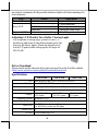
Adjusting LCD Monitor for a Better Viewing Angle
For an optimal viewing angle, please tilt the LCD
monitor up and down in the directions shown by the
arrow in the below figure. Please be advised not to
touch LCD panel while setting up the tilt angle for
HS-67xxW.
Driver Download
Please download the relevant driver that you need from the Posiflex website
(http://www.posiflex.com/en-global/Download/download).
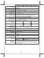
Specifications
HS-6710W
HS-6712W
HS-6714W
CPU
Intel Whisky Lake Core i3-8145UE/i5-8365UE
Memory
2 x DDR4 SO-DIMM
Storage Device
1 x M.2 port (M.2 2280) + 1 x SATA connector
Power Supply
24V/100W
Display
9.7” 1024 x 768
LCD Panel
12.1'' 1024 x
768 LCD panel
14'' 1366 x 768
LCD panel
Operating System
Windows 10 IoT
Touch Screen
Bezel-free P-CAP touch
Serial Port
2 x DB9 Port (on bottom I/O plate)
1 x RJ50 Port (on the top I/O plate)
Parallel Port
1
CR Port
1 Port controlling 2 CR

15
HS-6710W
HS-6712W
HS-6714W
VGA Port
D-SUB 15-pin , with 12V power for Posiflex LCD
monitors
Standard USB Port
4 x USB 3.0
Audio Port
1, Line Out / Mic-in combo
PS/2 KB Port
1
Ethernet Port
1 x 10/100/1000 Mb
LED Indicator
Power ON/ standby, bi-color LED indicators
Ethernet link LED indicator on Ethernet connector
Printer error & paper-out LED indicators
Extension Slot
1 x M.2 socket for optional WiFi module
Optional Items
MSR, Finger Print Sensor, RFID, 2D image Scanner, WiFi
module , iButton, 4G module
Dimension
(W x D x H in mm)
244 x 210 x 437
mm
297 x 210 x 476
mm
371 x 210 x 476
mm
Weight
(N.W. in kg)
4.2
5.3
5.8
Environmental
Requirements
Operating:0°C 〜 40°C, 20%RH - 90%RH
Storage:-20°C 〜 60°C, 10%RH - 90%RH
Regulation Rules
FCC/CE
3” Thermal printer with auto-cutter
Printer speed
250 mm/sec max.
Paper size
3” thermal paper or 2” thermal paper with 2” paper
separator
Posiflex 2D Scanner
Focal distance
120 mm
View Angel
Horizontal
approx. 38.0˚
Vertical
approx. 26.4˚
Supported
Symbology
UPC, EAN, Code 39, Codabar, Interleaved 2 of 5, Matrix 2
of 5, POSTNET, MSI/Plessey, UK/Plessey, Code 128,GS1-
Databar, GS1-Databar Limited, GS1-Databar Expanded,
QR Code, PDF417

16
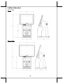
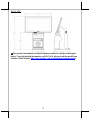
Outline Dimension
HS-6710W
HS-6712W


18
<MEMO>

19
<MEMO>

20
<MEMO>
-
 1
1
-
 2
2
-
 3
3
-
 4
4
-
 5
5
-
 6
6
-
 7
7
-
 8
8
-
 9
9
-
 10
10
-
 11
11
-
 12
12
-
 13
13
-
 14
14
-
 15
15
-
 16
16
-
 17
17
-
 18
18
-
 19
19
-
 20
20


Posiflex HS-6710W/6712W/6714W Manuel utilisateur
- Taper
- Manuel utilisateur
dans d''autres langues
Documents connexes
-
Posiflex HS-3610W/3612W/3614W Manuel utilisateur
-
-
-
-
-
-
-
-
-