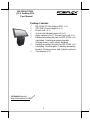
Posiflex HS-3310A/3314A Manuel utilisateur
- Catégorie
- Imprimantes d'étiquettes
- Taper
- Manuel utilisateur
Ce manuel convient également à

1
Package Contents
HS-3310A/3314A desktop POS (x 1)
24V/60W Power Adaptor (x 1)
Power cord (x 1)
3-inch wide thermal paper roll (x 1)
Paper separator for 2” thermal paper roll (x 1)
Desktop mounting kit pack for HS-3310A (x 1)
(including 1 desktop mounting bracket,
4 fixing screws, and 4 plastic anchors)
Desktop mounting kit pack for HS-3314A (x 1)
(including 1 bottom plate, 1 desktop mounting
bracket, 4 fixing screws, and 4 plastic anchors)
User manual (x 1)
15670902010 Ver. A0
http://www.posiflex.com
HS-3310A/3314A
JIVA Desktop POS
User Manual

2
SOME IMPORTANT NOTES
FCC NOTES
This system meets industry & government requirements and applicable
standards. This equipment generates, uses, and can radiate radio frequency
energy and, if not installed and used in accordance with the instructions
manual, may cause interference to radio communications. It has been tested
and found to comply with limits for a Class A digital device pursuant to
subpart B of Part 15 of FCC Rules, which are designed to provide reasonable
protection against interference when operated in a commercial environment.
Operation of this equipment in a residential area is likely to cause interference
in which case the user at his own expense will be required to take whatever
measures to correct the interference.
This device complies with part 15 of the FCC Rules. Operation is subject to
the following two conditions: (1) This device may not cause harmful
interference, and (2) this device must accept any interference received,
including interference that may cause undesired operation.
CE CLASS A WARNING
This equipment is compliant with Class A of CISPR 32. In a residential
environment this equipment may cause radio interference.
WARRANTY LIMITS
Warranty will terminate automatically when the machine is opened by any
person other than the authorized technicians. The user should consult his/her
dealer for the problem happening. Warranty voids if the user does not follow
the instructions in application of this merchandise. The manufacturer is by no
means responsible for any damage or hazard caused by improper application.
警告使用者
這是甲類的資訊產品,在居住的環境中使用時,可能會造成射頻干擾,在這種情
況下,使用者會被要求採取某些適當的對策。

3
BATTERY CAUTION NOTES
Dispose of used batteries according to the instructions.
Replacement of a battery with an incorrect type that can defeat a
safeguard (for example, in the case of some lithium battery types)
Disposal of a battery into fire or a hot oven, or mechanically crushing
or cutting of a battery that can result in an explosion.
Leaving a battery in an extremely high temperature surrounding
environment that can result in an explosion or the leakage of flammable
liquid or gas.
A battery subjected to extremely low air pressure that may result in an
explosion or the leakage of flammable liquid or gas.
BATTERIE ATTENTION NOTES
Jetez les piles usagées conformément aux instructions.
Remplacement d'une batterie avec un type incorrect qui peut annuler
une sauvegarde (par exemple, dans le cas de certains types de batterie
au lithium)
Mise au rebut d'une batterie dans le feu ou dans un four chaud, ou
écrasement ou coupure mécanique d'une batterie pouvant entraîner une
explosion.
Laisser une batterie dans un environnement environnant à des
températures extrêmement élevées pouvant entraîner une explosion ou
la fuite de liquide ou de gaz inflammable.
Une batterie soumise à une pression atmosphérique extrêmement basse
pouvant provoquer une explosion ou une fuite de liquide ou de gaz
inflammable.
警告
本電池如果更換不正確會有爆炸的危險,請依製造商說明書處理用過之
電池。

4
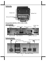
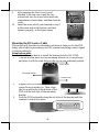
Cable Exit
Views of HS-3310A/3314A
Front View
Rear View
Power LED Indicator
Printer Error
LED Indicator
Printer Paper-Out
LED Indicator
3-Track Magnetic
Stripe Reader
(Optional)
Printed Paper Exit
HS-3310A/3314A
P-CAP Touch & LCD Panel
Fingerprint or iButton
Sensors (Optional)
Posiflex 2D Scanner
(Optional)
Paper Jam Rescue
Compartment
Top I/O Interface
Cable Cover
Bottom I/O Interface
Cable Cover
Feed Button

5
Left Side View
Right Side View
Power Button
Paper Roll Cover
Release Lever
RFID Card Reader
(Optional)

6
Bottom View
Views of I/O Interface of HS-3310A/3314A
Top I/O Interface
Bottom I/O Interface
Bottom I/O Interface
Rubber Pad
HDMI Port
Rubber Pad
Mounting holes
USB 3.0 Port
24V DC-IN Power Jack
Micro SD Card Slot
RJ-10 Cash Drawer Port
USB 2.0 Port
Micro USB OTG
Reset Button
Line Out Port
USB 2.0 Port
DB-9 COM Ports
RJ-45 LAN Port
12V DC-OUT
Power Jack

7
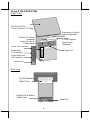
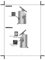
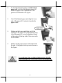
Connecting Power Adapter
Please refer to the following instructions on how to connect power adapter to
HS-3310A/3314A and to organize your cables.
1. Lay your desktop POS on a level surface
with its touch screen facing down as shown
in the figure.
2. Hold the bottom I/O interface cover with
your thumb and forefinger, and then gently
pull the cover outwards to remove the
cover.
3. Connect power adapter and I/O cables to
the bottom I/O interface.
4. Have the cover join to the wedge portions
of the bottom I/O interface.
5. Before pushing the cover back into place,
neatly thread the cables through the cable
exit.
6. Press down the cover to close the bottom
I/O interface chamber.
Cable Exit

8
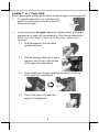
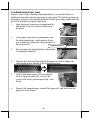
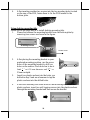
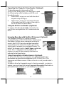
Loading 2” or 3” Paper Rolls
Before operating the printer, please follow the below steps to load a paper roll.
1. To open the paper roll cover, push down the
paper roll cover release lever in the direction
shown in the figure.
2. Before installing 2-inch paper roll in the thermal printer, place paper
separator in the paper roll compartment by following the instructions
below. If you are using 3” paper roll for the printer, please skip to
next step.
2.1. Hold the separator with the sharp-
pointed side down.
2.2. Push the sharp-pointed part of paper
separator into the slot on the bottom
of the paper roll compartment.
2.3. Slide another side of paper separator into the slot on the top
of the paper roll compartment.
2.4. Drop 2-inch paper roll inside the
paper roll compartment.

9
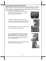
3. To load the thermal printer with the 3-inch
paper roll, just drop the thermal paper roll
inside the paper roll compartment of the
printer as illustrated in the figure.
4. Unroll the thermal paper and drag the loose
end of the paper till it extends towards the
paper cutter.
5. Make sure the loose end sticks out of the
opening of the paper roll compartment. Then,
close the paper roll cover by pushing it back
at the center of the top side of the cover with
a click sound.
6. Make sure the paper roll is well loaded with
the end of the paper sticking out as shown in
the figure.
To avoid paper jam or other printing errors, do NOT
press the paper roll cover release lever during printing.
Paper cutter

10
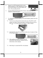
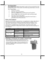
Troubleshooting Paper Jams
When it comes to the common printing problems, it is inevitable that you
might encounter the issue of paper jams at some point. The following steps are
provided to assist you in fixing the problem. Before proceeding, make sure that
your POS terminal is properly shut down.
1. Open the paper jams rescue compartment by
sliding the cover in the direction shown by
the arrow.
2. In the paper jams rescue compartment, find
the adjustment wheel, which mainly allows
you to manually adjust the cutting position of
the cutter blade.
3. Keep rotating the wheel until the cutter blade
is completely retracted.
4. Observe the cutter position through the paper exit slot to ensure the
cutter blade moves upward to the retracted position.
5. Gently push down paper roll cover release
lever to open the paper roll cover. If the
cover is still stuck, please repeat Step 3 and
Step 4.
6. Remove the jammed paper, reinstall the paper roll, and then close the
paper roll cover firmly.
Adjustment wheel

11
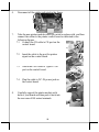
Replacing POS Receipt Printer Module
HS-3310A/3314A offers a quick solution to help you to replace POS receipt
printer module when there is a need. Please go through the steps described
below to achieve the purpose. Before proceeding the procedure, please ensure
that the terminal is completely shut down.
1. After laying POS terminal on a flat surface
with its bottom facing towards you, remove
the screw shown by the arrow.
2. Position the terminal with its screen facing
toward you, and then push down the paper roll
cover release lever to open the paper roll cover,
3. Inside the paper roll compartment, remove the
two screws indicated by the arrows.
4. While supporting the terminal with one hand,
grab the right-hand side of the terminal and
then pull the front cover towards you with
force to separate the printer module from the
rear case of HS-series
5. From the left-hand side of the terminal, remove
the front cove from the rear case.

12
6. Disconnect all the cables indicated in the figure.
7. Take the new printer module which you wish to replace with, and then
connect the cables to the printer control board as indicated in the
following figures.
7.1 Connect the CR cable to CR port on the
control board.
7.2 Insert the cable to the port for printer
signal on the control board.
7.3 Attach the USB cable to Type-B USB
port on the control board.
7.4 Plug the cable to DC-IN power jack on
the control board.
8. Carefully support the printer module with
both of your hands and then push it back into
the rear case of HS-series terminals.

13
9. After ensuring the front cover is well
attached to the rear case, insert the two
screws back into the screw holes inside the
compartment, secure them, and then close the
cover.
10. Insert the screw which you removed in step 1
to the screw hole at the bottom, and then
fasten it properly, as the figure shows.
Mounting the POS onto a Table
This section will describe two alternative solutions to help you fix the POS
firmly onto a table in preventing your POS system from being rocked, tipped
or tilted accidentally.
Using bottom plate
Please follow the steps below to install the bottom plate for HS-3114A.
1. Take the bottom plate with the mounting bracket out of the package,
and place it with its screw holes on the top in your preferred position.
2. Support your POS terminal with its
screen facing towards you. Then, align
the two screw bolts on the bottom of the
POS with the rail slots of the mounting
bracket.
3. Push the POS backwards along the rail slots of the bracket until the
terminal is locked into place.
Bottom Plate
Mounting bracket
Screw holes

14
4. After inserting another two scerws into the two mouting holes located
on the rear of the POS, fasten them to fix the POS termial to the
bottom plate.
Using desktop-mounting kits
Please follow the steps below to install desktop-mounting kits.
1. Please first release the mounting bracket from the bottom plate by
removing two screws as shown in the figure.
2. After placing the mounting bracket in your
preferred mounting position, use the screw
holes of the mounting bracket to drill two
holes on the surface. Each hole has to be at
least
4
1
” or 6.25 mm diameter and
8
3
1
” or
35mm in depth.
3. Insert two plastic anchors into the holes you
drilled in step 2 and use a hammer to tap the
plastic anchors into the drilled holes.
4. After well attaching two screw holes of the mounting bracket to the
plastic anchors, insert two self-tapping screws into the plastic anchors
through the mounting bracket and then secure the bracket.
Mounting bracket
Bottom Plate

15
5. Support your POS terminal with its screen
facing towards you. then, align the two screw
bolts on the bottom of the POS with the rail
slots of the mounting bracket.
6. Push the POS backward along the rail slots of the bracket until the
terminal is locked into place.
7. To completely mount the desktop POS onto the table, please follow the
steps below.
7.1 Use the two mouting holes located on the rear of the POS to drill
another two holes on the same surface. Each hole also has to be at
least
4
1
” or 6.25 mm diameter and
8
3
1
” or 35mm in depth.
7.2 Push the POS in the direction shown by the arrow to reomve it from
the mouting bracket.
7.3 After pushing two plastic anchors into the
drilled holes, tap the plastic anchors into the
drilled holes with a hammer.
7.4 Refer Step 6 to mount the POS to the bracket.

16
7.5 Apply two self-tapping screws through the mounting holes into the
two plastic anchors. Then, fasten the screws to completely lock the
POS onto the table.
Installing a Customer Display to HS-3310A/3314A
HS-3310A/3314A also allows you to additionally install a customer display to
expand its functionality. Based on the model of the second display, the step-
by-step instructions are provided in its own user guide to help you mount it
onto your POS system. Please refer to the relevant user manual for detailed
information.
Powering ON/OFF the HS-3310A/3314A
Power ON HS-3310A/3314A
To power on the POS, gently press and hold down the power button for at least
1 second till the Power LED indicator turns solid blue, and then release the
button.
Power OFF HS-3310A/3314A
To initiate a system shutdown on Android operating system, you are expected
to follow the following procedures to turn off your system:
1. Press down the power button for a few seconds until a pop-up window
appears.
2. Tap Power off on the screen to shut down your system. If you need to
reboot your system right away, please be advised to wait at least three
seconds to do so.
However, it is likely that HS-3310A/3314A cannot restart or shut down
normally due to the unexpected reasons. In such a case, it is suggested to
initiate a shutdown by keeping holding down the power button more than 10
seconds.

17
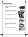
Operating the Magnetic Stripe Reader (Optional)
To have the magnetic stripe reader of HS-
3310A/3314A work properly, you must bear in mind
the following tips while swiping your MSR cards
through the reader.
1. Make sure to swipe your card with the side of
magnetic stripe facing up.
2. Make sure to swipe your card along the track
of the reader from left to right or from right to
left in the direction shown below.
Using the RFID Card Reader (Optional)
To retrieve data through the RFID card reader, tap
your Mifare card against the RFID reader as shown
below.
Scanning Barcodes with Posilfex 2D Scanner (Optional)
The integrated Posiflex 2D Scanner is another
prominent feature of HS-3310A/3314A. With its hand-
free design, it offers a more convenient solution for
users to read 1D/2D barcodes and then transmitted
scanned data to the terminal for further processing,
which greatly increases your working efficiency. By
default, the scanner is set to Auto Trigger operational
mode. Also, to adjust the scanning angle of the
scanner, you may tilt the scanner up and down as
indicated in the figure below.
Using Fingerprint or iButton Sensors (Optional)
As for access control to your computer, two optional identification
mechanisms are provided and integrated in HS-3310A/3314A: The
fingerprint and iButton sensors. Either will work to verify an individual’s
identity.
In order to allow the fingerprint sensor to function normally, you have to
register your own finger first using Fingerprint Recognition Tool which is
pre-installed and accessible on your desktop of your system.
Fingerprint Sensor
iButton Sensor

18
Self-Diagnosing your Printer
The variety of diagnostic tips is provided in aim to help you efficiently
troubleshoot printer problems. Please carefully go through the following
descriptions to understand how each function provided works.
Self Test
A self-test page, generated by Self Test function, generally contains
useful information describing current printer configurations. Please
follow the instructions described below to perform a self-test:
1. Power OFF printer.
2. Hold down Feed button, and then power on the printer.
3. Release Feed button after the printer emits one beep sound.
4. The printer will print a test page displaying the self-test result.
5. A flashing red Paper Out LED indicates the printing is still
processing. In this case, you may either choose to reboot your
printer or keep pressing Feed button to further create the hex
dump and Ethernet info print-outs until the indicator stops
blinking red.
Software Switch Reset
Software Switch Reset is the specially-designed function aimed to
facilitate the factory reset process. Please go through the following
instructions to reset your printer to factory settings using Software
Switch Reset.
1. Power OFF printer.
2. Open the cover of the printer.
3. Press Feed button three times after powering on the printer.
4. Close the cover of the printer.
5. The printer will emit one long beep sound and then print a test
page displaying software switch setting
6. Afterwards, the printer will restart by itself.
7. Ensure that all the software switches are correctly set to
factory default as follows:
Software switch number
Pin Number
SW1
Pin 1 ~ 8 = OFF
SW2
Pin 1 ~ 8 = OFF
SW3
Pin 1 ~ 8 = OFF
SW4
Pin 1 ~ 8 = OFF

19
Hex Dump Mode
Hex Dump Mode enables the printer to print out the received data in the
hexadecimal format. Please refer to the following instructions to activate
Hex Dump Mode.
1. Power OFF printer.
2. Open the cover of the printer.
3. Hold down Feed button, and then power on the printer.
4. Release Feed button after the printer emits one beep sound.
5. Close the cover for the printer.
6. The printer will be put into Hex Dump Mode and ready to
print data received from the host.
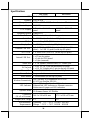
Status LED Indicator
After HS-3310A/3314A is powered on, it is significant to observe the status of
LED indicators anytime to ensure your system functions normally. More
importantly, knowing how to interpret the status indicators enables you to
perform basic troubleshooting more efficiently. The below chart is thus
provided to enumerate all the possible indicator lights with their meanings for
your reference.
LED
Status
Description
POWER LED
Solid orange
System standby
Solid blue
System ON
Error LED
Solid red
Cover open
Flashing red
Operating temperature of
thermal head is high
Paper-out LED
Solid red
Out of Paper
Adjusting LCD Monitor for a Better Viewing Angle
For an optimal viewing angle, please tilt the LCD
monitor up and down in the directions shown by the
arrow in the below figure. Please be advised not to
touch LCD panel while setting up the tilt angle for
HS-3310A//3314A.

20
Specifications
HS-3310A
HS-3314A
CPU
Rockchip RK3399
Memory
2GB or 4GB
Storage Device
16GB or 32GB eMMC onboard + micro SD slot
Power Adaptor
24V/60W
LCD Display
9.7” 1024 x 768 LCD
panel
14" 1366 x 768 LCD
panel
Operating System
Android 9.0
Touch Screen
PCAP touch with multi-touch support
Serial Port
2 x DB9 Port (on the bottom I/O plate)
CR Port
1, controlling 2 CR (24V drive)
Display Port
1 x HDMI port (on the top I/O plate)
External USB Port
3, 2 (USB 3.0 + USB 2.0) ports (on the bottom I/O
plate) + 1 x USB 2.0 ports (on the top I/O plate)
OTG USB
1 x Micro USB (USB 3.0) (on the top I/O plate)
Internal USB Port
1 x 7-pin for 4G module
1 x 12-pin for printer
1 x 5-pin for HUB board
1 x 5-pin (reserved)
Audio Port
1 x 2W speaker (internal wafer) + 1 x audio jack
DC-In Jack
1 x 24V DC-In, 3-pin (on the bottom I/O plate)
1 x 12V DC-Output jack, 2-pin (on the top I/O plate)
Ethernet Port
1 x 10/100/1000 Mb (on the bottom I/O plate)
Power Button
1 x power button
Reset Button
1 x reset button (on the top I/O plate)
Wireless Connectivity
WiFi via mini-PCIe expansion slot or USB
4G LTE via Posiflex SM-140
LED Indicator
Power ON/ standby, bi-color LED indicators
Ethernet link LED indicator on Ethernet connector
Printer error & paper-out LED indicators
Optional Items
MSR, RFID Reader, Fingerprint or iButton Sensors,
2D Scanner Sensor, 4G Module
Dimension
(W x D x H in mm)
244.5 x 198 x 434 mm
371.5 x 198 x 473 mm
Weight (N.W. in kg)
4.2
5.8
Environmental
Requirements
Operating: 0°C 〜 40°C, 20%RH - 90%RH
Storage: -20°C 〜 70°C, 10%RH - 90%RH
La page est en cours de chargement...
La page est en cours de chargement...
La page est en cours de chargement...
La page est en cours de chargement...
-
 1
1
-
 2
2
-
 3
3
-
 4
4
-
 5
5
-
 6
6
-
 7
7
-
 8
8
-
 9
9
-
 10
10
-
 11
11
-
 12
12
-
 13
13
-
 14
14
-
 15
15
-
 16
16
-
 17
17
-
 18
18
-
 19
19
-
 20
20
-
 21
21
-
 22
22
-
 23
23
-
 24
24


Posiflex HS-3310A/3314A Manuel utilisateur
- Catégorie
- Imprimantes d'étiquettes
- Taper
- Manuel utilisateur
- Ce manuel convient également à
dans d''autres langues
- English: Posiflex HS-3310A/3314A User manual
Documents connexes
-
Posiflex HS-3610W/3612W/3614W Manuel utilisateur
-
-
-
-
-
-
-
-
-
Autres documents
-
Star Micronics TSP800 Series Manuel utilisateur
-
-
-
Star Micronics TSP700 Series Manuel utilisateur
-
-
OKI PT341 Dual Mode d'emploi
-
-
Citizen CT-S281L Manuel utilisateur
-
Sharper Image RFID Combination Locking Wallet Le manuel du propriétaire