Sony STR-ZA5000ES Guide d'installation
- Catégorie
- Récepteurs AV
- Taper
- Guide d'installation

STR-ZA5000ES
MULTI CHANNEL
AV RECEIVER
Installation Guide
US
Guide d’installation
FR
Guía de instalación
ES
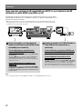
Before installing the receiver, be sure to update the receiver to the latest software
version.
Avant d’installer l’ampli-tuner, veillez à le mettre à jour à la dernière version de logiciel.
Antes de instalar el receptor, asegúrese de actualizar el receptor a la versión de software
más reciente.

2
GB
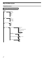
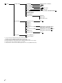
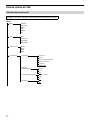
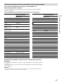
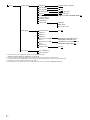
Map of GUI Menu System
Using the home menu
Menu items underlined are default settings.
Home
Watch
BD/DVD
SAT/CATV
GAME
STB
VIDEO
TV
Listen
AUX
SACD/CD
FM TUNER
AM TUNER
Custom Preset
Movie
Music
Party
Night
Sound Effects
Sound Field 2ch Stereo
Direct
Auto Format Decoding
Dolby Surround
Neural:X
Multi Stereo
Equalizer
Sound Optimizer
Normal
Low
Off
InCeiling Speaker Mode Front & Center
Front
Off
Pure Direct
On
Off

3
GB
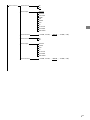
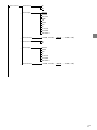
Zone Controls
Zone2 Power
On
Off
Zone2 Input
SOURCE
BD/DVD
SAT/CATV
GAME
STB
VIDEO
AUX
TV
SA-CD/CD
FM TUNER
AM TUNER
Zone2 Volume
(+23.0dB, +22.5dB, …, –40.0dB, …, –92.0dB, –∞dB)
Zone3 Power
On
Off
Zone3 Input
SOURCE
VIDEO
AUX
TV
SA-CD/CD
FM TUNER
AM TUNER
Zone3 Volume
(+23.0dB, +22.5dB, …, –40.0dB, …, –92.0dB, –∞dB)

4
GB
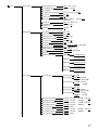
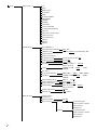
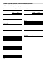
Setup
Input Setup* *
Icon
Name
Watch/Listen
Show/Hide
HDMI
OPTICAL/COAXIAL
COMPONENT
VIDEO IN
AUDIO IN
Input Mode
Preset Sound Field
In-Ceiling Speaker Mode
A/V Sync
Subwoofer Low Pass Filter
Subwoofer Level
Preset Gain Level
Trigger 1
Trigger 2
Trigger 3
Speaker Setup
Auto Calibration*
Automatic Phase Matching
(Auto, Off)
Calibration Type
(Full Flat, Engineer, Front Reference, Off)
Speaker Pattern
Speaker Connections
SB Speaker Assign
(Zone2, Bi-Amp, Front B, Off)
Height1 SP Assign
(Zone2, Off)
Size*
(Large, Small)
Distance*
(32ft 9in, 32ft 8in, …, 9ft 10in, …,
6ft7in, 6ft 6in)
Level*
(+10.0dB, +9.5dB, …, 0.0dB, …, –9.5dB,
–10.0dB)
Test Tone*
Crossover Frequency*
(40Hz, 50Hz, …, 120Hz, …, 190Hz, 200Hz)
Equalizer*
(+10.0dB, +9.0dB, …, 0.0dB, …, –9.0dB,
–10.0dB)
Center Speaker Lift Up
(10, 9, 8, …, 2, 1, Off)
Surround Speaker Position
(Front, Back)
Speaker Relocation
(Type A, Type B, Off)
Ceiling Height
(32ft 9in, 32ft 8in, …, 9ft 0in, …,
6ft7in, 6ft 6in)
Speaker Impedance
(8, 4)
Distance Unit
(feet, meter)
Network Setup
Internet Setup*
Information*
Network Standby
(On, Off)
Music Connect
Device1 Connected Device
Input for Music Connect1
Preset Volume
Output Zone
Device2 Connected Device
Input for Music Connect2
Preset Volume
Output Zone

5
GB
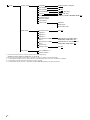
Setup
Audio Setup
Digital Legato Linear
(Auto 1, Auto 2, Off)
Sound Optimizer
(Normal, Low, Off)
Sound Field*
In-Ceiling Speaker Mode
(Front & Center, Front, Off)
Pure Direct
(On, Off)
Subwoofer Low Pass Filter
(On, Off)
A/V Sync
(300ms, 290ms, …, 10ms, 0ms,
HDMIAuto)
Dual Mono
(Main, Sub, Main/Sub)
Dynamic Range
Compressor
(Auto, On, Off)
Neural:X
(On, Off)
HDMI Setup
4K Scaling (Auto, Off)
Control for HDMI
(On, Off)
Standby Linked to TV
(Auto, On, Off)
Audio Return Channel
(On, Off)
Pass Through
(Auto, On, Off)
Audio Out
(AMP, TV+AMP)
Zone2 Audio Out
(AMP, Zone2 TV+AMP, Zone2 AMP)
Subwoofer Level
(Auto, +10dB, 0dB)
HDMI Out B Mode
(Main, Zone2)
Priority
(Main&Zone2, Main Only)
Fast View
(Auto, Off)
HDMI Signal Format
HDMI IN 1 (Standard format,
Enhanced format)
HDMI IN 2
(Standard format,
Enhanced format)
HDMI IN 3
(Standard format,
Enhanced format)
HDMI IN 4
(Standard format,
Enhanced format)
HDMI IN 5
(Standard format,
Enhanced format)
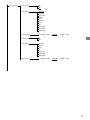
Zone Setup
Zone Controls Zone2 Power (On, Off)
Zone2 Input
(SOURCE, BD/DVD, …,
FM TUNER, AM TUNER)
Zone2 Volume
(+23.0dB, +22.5dB, …,
–40.0dB, …, –92.0dB,
–∞dB)
Zone3 Power
(On, Off)
Zone3 Input (SOURCE, VIDEO, …,
FM TUNER, AM TUNER)
Zone3 Volume
(+23.0dB, +22.5dB, …,
–40.0dB, …, –92.0dB,
–∞dB)
Main Preset Volume
(+23.0dB, +22.5dB, …, –92.0dB, –∞dB, Off)
Main Max Volume
(+23.0dB, +22.5dB, ..., –40.0dB)
Zone2 Preset Volume
(+23.0dB, +22.5dB, …, –92.0dB, –∞dB, Off)
Zone2 Max Volume
(+23.0dB, +22.5dB, ..., –40.0dB)
Zone2 Line Out
(Variable, Fixed)
Zone3 Preset Volume
(+23.0dB, +22.5dB, …, –92.0dB, –∞dB, Off)
Zone3 Max Volume
(+23.0dB, +22.5dB, ..., –40.0dB)
Zone3 Line Out
(Variable, Fixed)

6
GB
Setup
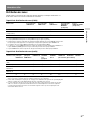
System Setup
Language
(English, Español, Français)
Auto Display
(On, Off)
Auto Standby
(On, Off)
Volume Display
(Relative, Absolute)
Dimmer
(Bright, Dark, Off)
Sleep
(2:00:00, 1:30:00, 1:00:00, 0:30:00, Off)
Software Version
Network Update
USB Update*
Tuner Setup*
FM Mode
Name Input
Preset Gain Level
Install Setup
External Control
(On, Off)
Trigger 1*
Trigger 2*
Trigger 3*
Test Picture for HDMI
Out A
(4K/60Hz/4:4:4, 4K/24Hz/4:4:4,
1080p/60Hz, 480p/60Hz, Off)
Test Picture for HDMI
Out B
(4K/60Hz/4:4:4*, 4K/24Hz/4:4:4,
1080p/60Hz, 480p/60Hz, Off)
Save/Load*
Settings Lock*
(On, Off)
Easy Setup
Auto Calibration*
Internet Setup*
* You can select the following inputs in the Input Setup screen.
BD/DVD, SAT/CATV, GAME, STB, VIDEO, AUX, TV, SA-CD/CD
* You can set up each input using these menu items in [Input Setup].
* Detailed information of these menu items is displayed after you select the settings.
* The menu item can be adjusted against each speaker.
* This parameter cannot be selected when [Zone2] is selected for [HDMI OUT B Mode].

7
GB
Table of Contents
Map of GUI Menu System ................................................................................................ 2
Using the home menu ......................................................................................2
Preparations
Preparing the receiver ......................................................................................................8
Outline dimensional drawing ........................................................................... 8
Attaching/removing the front cover ................................................................8
Mounting the receiver using the rack mount kit .............................................................9
Connections
Connecting a 4K TV that supports HDCP 2.2 and a 4K streaming box
using a 4K-compatible HDMI cable ........................................................................... 10
Connecting a device that supports high bandwidth video formats ..............................11
Making a connection for PoE (Power over Ethernet) ..................................................... 11
Making a multi-zone connection ....................................................................................12
Speaker patterns and terminals to be connected ..........................................................13
Settings
Setting up the receiver ................................................................................................... 18
Activating the network standby mode .......................................................... 18
Turning on the control mode to make an external controller connection .... 18
Outputting a test tone from each speaker (TestTone) .................................. 18
Displaying a test screen (Test Picture) ........................................................... 18
Adjusting the sound balance automatically (Auto Calibration) .................... 18
List of messages after Auto Calibration measurements ............................... 19
Saving/loading settings of the receiver ........................................................ 19
Linking with a Hi-Fi music system ..................................................................20
Mixing separate audio/video inputs (Last video mode) ...............................20
Setting the in-ceiling speaker mode ..............................................................20
Updating the software via the network ..........................................................21
Updating the software with a USB flash drive ................................................21
Setting up through a web browser .................................................................21
Using the PING button ....................................................................................21
When using a TV compatible with Dolby Digital Plus output ....................... 22
Configuring the receiver to allow a Crestron Control System to control the
receiver .................................................................................................... 22
Using the hidden commands
Performing commands using the receiver .................................................................... 23
Performing commands using the supplied remote control ......................................... 23
Changing the remote control code ............................................................... 23
Turning on transmitting mode of the discrete code for the main zone ........24
Turning on transmitting mode of the discrete code for Zone 2/Zone 3 ...... 25
Useful information
Zone distribution ............................................................................................................26

8
GB
Preparations
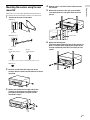
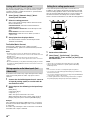
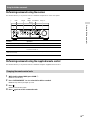
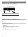
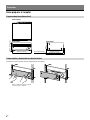
Preparing the receiver
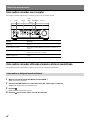
Outline dimensional drawing
Top
Front Side
174 mm (6 7/8 in)
430 mm (17 in) 378 mm (15 in)
410 mm (16 1/4 in)
10 mm (13/32 in)
Attaching/removing the front cover
The front cover can be completely removed from the receiver.
Remove the front cover by inserting
your fingers under the cover.

9
GB
Preparations
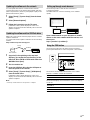
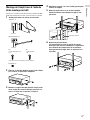
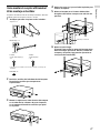
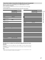
Mounting the receiver using the rack
mount kit
Make sure to use a “WS-RE1” dedicated rack mount kit for
this receiver when mounting the receiver on a rack mount.
1 Check that all parts are included.
Bracket × 2
Insulator
Blank panel × 1
Insulator
Screw
+P U10-32×3/4 (inch)*
× 6
Screw
+T M5×18 (mm)*
× 6
* Select the correct screws according to the type of rack.
Washer × 6
2 Remove screws from the right side of the
receiver. Do not remove screws other than those
specified.
3 Mount the bracket on the right side of the
receiver in the order of the step numbers
printed on the bracket using the screws
removed in step 2.
4 Repeat steps 2 and 3 for the left side to mount
the bracket.
5 Mount the receiver to the rack system. Make
sure to perform this step with more than one
person.
Rack mount
6 Mount the blank panel.
(The blank panel hides the legs of the receiver to
give it a cleaner look. Aligning the height of the
receiver and blank panel lets it fit into a 4U size
space.)

10
GB
Connections
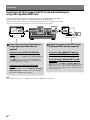
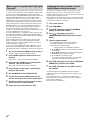
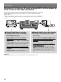
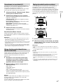
Connecting a 4K TV that supports HDCP 2.2 and a 4K streaming box
using a 4K-compatible HDMI cable
To enjoy audio from 4K content such as 4K movies, connect the HDMI output/input jacks of
each device that supports HDCP 2.2* using HDMI cables, as illustrated below.
* HDCP 2.2 (Highbandwidth Digital Content Protection System Revision 2.2) is newly enhanced copyright
protection technology that is used to protect content such as 4K movies from Studios.
4K media player 4K TV or 4K projector
Connect the receiver to a 4K media player
using a High Speed HDMI cable (not
supplied).
Connect the receiver to your 4K TV using a
High Speed HDMI cable (not supplied).
If you are using an FMP‐X10/X5 Media
Player:
Connect the cable to the HDMI OUT 1 (for AUDIO VIDEO) jack
of the player.
Select [
(Settings)] [Sound] [Audio from HDMI OUT]
[HDMI OUT 1] in the Home menu of the FMP-X10/X5 Media
Player after Initial Setup is complete.
If you are using a different 4K media
player:
Connect the cable to one of the HDCP 2.2-compatible
HDMI output jacks. For details, refer to the operating
instructions supplied with your player.
If you are using a BRAVIA TV with the
series name X950B, X900B or X850B:
Connect the cable to the HDMI IN 1 jack of your TV.
If you are using a different 4K TV or 4K
projector:
Connect to one of the HDCP 2.2-compatible HDMI input
jacks. If the jack is not compatible with the ARC (Audio Return
Channel) function, also connect an optical digital cable. For
details, refer to the operating instructions supplied with your
4K TV or 4K projector.
Note
•Sony recommends that you use an HDMI-authorized cable or HDMI cable made by Sony.

11
GB
Connections
Connecting a device that supports high bandwidth video formats
When you use high bandwidth video formats such as 4K/60p YCbCr 4:4:4/YCbCr 4:2:2/
RGB4:4:4 or 4K/60p YCbCr 4:2:0 Deep Color (Deep Colour) (10 bit or 12 bit), be sure to set
[HDMI Signal Format].
1 Select [Setup] - [HDMI Setup] - [HDMI Signal Format] from the home menu.
2 Select the HDMI input you want to apply the setting.
3 Select [Enhanced format].
Notes
•For details on the high bandwidth video format, refer to the Help Guide.
•When [Enhanced format] is selected, we recommend to use a Premium High Speed HDMI Cable with
Ethernet, which can support bandwidth up to 18 Gbps.
•When [Enhanced format] is selected, some devices (cable box or satellite box, Blu-ray Disc player, and
DVD player) may not work. In this case, select [Standard format].
•If your TV have similar menu for high bandwidth video format, check the setting on the TV menu when
you select [Enhanced format] on this receiver. For details on the TV menu setting, refer to the operating
instructions of the TV.
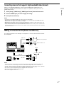
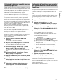
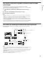
Making a connection for PoE (Power over Ethernet)
The following illustration is an example of configuration of a home network with the receiver
and a computer.
LAN cable
Modem
Wireless access point, etc.
Network camera, etc.
LAN cable
LAN cable
LAN cable
Computer
Router
Internet
Notes
•Connect a router to one of ports 1 to 8 on the receiver using a single LAN cable. Do not connect the
same router to the receiver using more than one LAN cable. Doing so may cause a malfunction.
•Ports No. 1 and No. 2 support PoE (Power over Ethernet, Alternative A). If you connect a PoE-compatible
device to one of these ports, power will be supplied to the device from the receiver.
•You can also connect a device that does not support PoE to the PoE port.
•The PoE port lights in red while supplying power.
•This receiver supports PoE Class 3.

12
GB
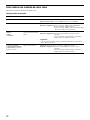
Making a multi-zone connection
This receiver allows various multi-zone connections.
Sample setup
Output jack Connected device Connection method
HDMI OUT A TV Connection: Connect to the TV using the HDMI OUT A jack.
Operation of the receiver: Press HDMI OUT to select HDMI A.
HDMI OUT B TV Connection: Connect to the TV using the HDMI OUT B jack.
Setup menu: Select [Setup] - [HDMI Setup] - [HDMI Out B Mode] - [Zone2] from
the home menu.
Select [Setup] - [HDMI Setup] - [Zone2 Audio Out] - [Zone2 TV +
AMP] from the home menu.
SPEAKERS terminals
FRONT A
CENTER
SURROUND
5-channel speakers and 1 or 2
subwoofer(s)
Connection: Connect the speakers and subwoofer(s).
Setup menu: Perform Auto Calibration and set the following settings.
Select [Setup] - [Speaker Setup] - [SB Speaker Assign] - [Zone2]
from the home menu.
Tip
•Select [Setup] - [Input Setup] - [In-Ceiling Speaker Mode] - [On] when you use
the in-ceiling speakers.
SPEAKERS terminals
SURROUND BACK (FRONT B/
BI-AMP/ZONE 2) (when
assigned to Zone 2)
2-channel speakers Connection: Connect Zone 2 L/R speakers.
Setup menu: Perform Auto Calibration and set the following settings.
Select [Setup] - [Speaker Setup] - [SB Speaker Assign] - [Zone2]
from the home menu.

13
GB
Connections
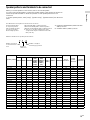
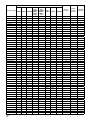
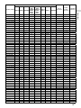
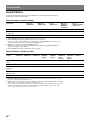
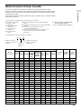
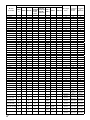
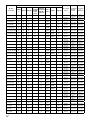
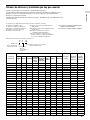
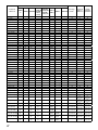
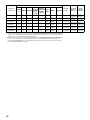
Speaker patterns and terminals to be connected
When you connect speakers to the receiver, refer to the following table.
You can use the following table to confirm the speaker patterns supported by the receiver as
well as the speaker terminals to which the speakers of each speaker pattern are to be
connected.
To set the speaker pattern, select [Setup] - [Speaker Setup] - [Speaker Pattern] from the home
menu.
The abbreviations and symbol used in the list are as follows.
FH: Front high speakers
TF: Top front speakers
TM: Top middle speakers
TR: Top rear speakers
RH: Rear high speakers
FD: Front Dolby Atmos enabled speakers
SRD: Surround Dolby Atmos enabled speakers
SBD: Surround back Dolby Atmos enabled speakers
: There are no speaker terminals that can be
assigned and output is enabled from the PRE
OUT jacks only.
SB: SPEAKERS SURROUND BACK (FRONT B/BI-AMP/
ZONE 2) terminals
H1: SPEAKERS HEIGHT 1 (ZONE 2) terminals
What the numbers in the speaker pattern indicate:
7 . 1 . 4
Number of speakers
located at listener’s
level
Number of
subwoofers
Number of height or
overhead (top) speakers
Speaker pattern
SPEAKERS terminals / PRE OUT jacks
Zone 2
connection
*
1
Front B
speaker
connection
*
1
Bi-amplifier
connection
*
1
FRONT A
CENTER SURROUND
SURROUND
BACK
(FRONT B/
BI-AMP/
ZONE 2)
(single)
SURROUND
BACK
(FRONT B/
BI-AMP/
ZONE 2)
(L/R)
HEIGHT 1
(ZONE 2)
HEIGHT 2
SUBWOOFER
2.0
- - - - - - - SB or H1 SB SB
2.0.2 (TM)
- - - -
(TM)
- - SB SB SB
2.0.2 (FD)
- - - -
(FD)
- - SB SB SB
2.1
- - - - - -
SB or H1 SB SB
2.1.2 (TM)
- - - -
(TM)
-
SB SB SB
2.1.2 (FD)
- - - -
(FD)
-
SB SB SB
3.0
- - - - - - SB or H1 SB SB
3.0.2 (TM)
- - -
(TM)
- - SB SB SB
3.0.2 (FD)
- - -
(FD)
- - SB SB SB
3.1
- - - - -
SB or H1 SB SB
3.1.2 (TM)
- - -
(TM)
-
SB SB SB
3.1.2 (FD)
- - -
(FD)
-
SB SB SB
4.0
-
- - - - - SB or H1 SB SB
4.0.2 (FH)
-
- -
(FH)
- - SB SB SB
4.0.2 (TM)
-
- -
(TM)
- - SB SB SB
4.0.2 (FD)
-
- -
(FD)
- - SB SB SB
4.0.2 (SRD)
-
- -
(SRD)
- - SB SB SB
4.0.4 (FH+TM)
-
- -
(FH) (TM)*
2
- SB SB SB
4.0.4 (FH+TR)
-
- -
(FH) (TR)*
2
- SB SB SB
4.0.4 (FH+RH)
-
- -
(FH) (RH)*
2
- SB SB SB
4.0.4 (TF+TM)
-
- -
(TF) (TM)*
2
- SB SB SB
4.0.4 (TF+TR)
-
- -
(TF) (TR)*
2
- SB SB SB
4.0.4 (TF+RH)
-
- -
(TF) (RH)*
2
- SB SB SB

14
GB
Speaker pattern
SPEAKERS terminals / PRE OUT jacks
Zone 2
connection
*
1
Front B
speaker
connection
*
1
Bi-amplifier
connection
*
1
FRONT A
CENTER SURROUND
SURROUND
BACK
(FRONT B/
BI-AMP/
ZONE 2)
(single)
SURROUND
BACK
(FRONT B/
BI-AMP/
ZONE 2)
(L/R)
HEIGHT 1
(ZONE 2)
HEIGHT 2
SUBWOOFER
4.0.4 (TM+TR)
-
- -
(TM) (TR)*
2
- SB SB SB
4.0.4 (TM+RH)
-
- -
(TM) (RH)*
2
- SB SB SB
4.0.4 (FD+SRD)
-
- -
(FD) (SRD)*
2
- SB SB SB
4.1
-
- - - -
SB or H1 SB SB
4.1.2 (FH)
-
- -
(FH)
-
SB SB SB
4.1.2 (TM)
-
- -
(TM)
-
SB SB SB
4.1.2 (FD)
-
- -
(FD)
-
SB SB SB
4.1.2 (SRD)
-
- -
(SRD)
-
SB SB SB
4.1.4 (FH+TM)
-
- -
(FH) (TM)*
2
SB SB SB
4.1.4 (FH+TR)
-
- -
(FH) (TR)*
2
SB SB SB
4.1.4 (FH+RH)
-
- -
(FH) (RH)*
2
SB SB SB
4.1.4 (TF+TM)
-
- -
(TF) (TM)*
2
SB SB SB
4.1.4 (TF+TR)
-
- -
(TF) (TR)*
2
SB SB SB
4.1.4 (TF+RH)
-
- -
(TF) (RH)*
2
SB SB SB
4.1.4 (TM+TR)
-
- -
(TM) (TR)*
2
SB SB SB
4.1.4 (TM+RH)
-
- -
(TM) (RH)*
2
SB SB SB
4.1.4 (FD+SRD)
-
- -
(FD) (SRD)*
2
SB SB SB
5.0
- - - - - SB or H1 SB SB
5.0.2 (FH)
- -
(FH)
- - SB SB SB
5.0.2 (TM)
- -
(TM)
- - SB SB SB
5.0.2 (FD)
- -
(FD)
- - SB SB SB
5.0.2 (SRD)
- -
(SRD)
- - SB SB SB
5.0.4 (FH+TM)
- -
(FH) (TM)*
2
- SB SB SB
5.0.4 (FH+TR)
- -
(FH) (TR)*
2
- SB SB SB
5.0.4 (FH+RH)
- -
(FH) (RH)*
2
- SB SB SB
5.0.4 (TF+TM)
- -
(TF) (TM)*
2
- SB SB SB
5.0.4 (TF+TR)
- -
(TF) (TR)*
2
- SB SB SB
5.0.4 (TF+RH)
- -
(TF) (RH)*
2
- SB SB SB
5.0.4 (TM+TR)
- -
(TM) (TR)*
2
- SB SB SB
5.0.4 (TM+RH)
- -
(TM) (RH)*
2
- SB SB SB
5.0.4 (FD+SRD)
- -
(FD) (SRD)*
2
- SB SB SB
5.1
- - - -
SB or H1 SB SB
5.1.2 (FH)
- -
(FH)
-
SB SB SB
5.1.2 (TM)
- -
(TM)
-
SB SB SB
5.1.2 (FD)
- -
(FD)
-
SB SB SB
5.1.2 (SRD)
- -
(SRD)
-
SB SB SB
5.1.4 (FH+TM)
- -
(FH) (TM)*
2
SB SB SB
5.1.4 (FH+TR)
- -
(FH) (TR)*
2
SB SB SB
5.1.4 (FH+RH)
- -
(FH) (RH)*
2
SB SB SB
5.1.4 (TF+TM)
- -
(TF) (TM)*
2
SB SB SB
5.1.4 (TF+TR)
- -
(TF) (TR)*
2
SB SB SB
5.1.4 (TF+RH)
- -
(TF) (RH)*
2
SB SB SB
5.1.4 (TM+TR)
- -
(TM) (TR)*
2
SB SB SB
5.1.4 (TM+RH)
- -
(TM) (RH)*
2
SB SB SB
5.1.4 (FD+SRD)
- -
(FD) (SRD)*
2
SB SB SB
5.0 (SB)
-
- - - - H1
Not available Not available
5.0.2 (SB+FH)
-
-
(FH)
- -
Only PRE OUT Not available Not available
5.0.2 (SB+TM)
-
-
(TM)
- -
Only PRE OUT Not available Not available
5.0.2 (SB+FD)
-
-
(FD)
- -
Only PRE OUT Not available Not available
5.0.2 (SB+SRD)
-
-
(SRD)
- -
Only PRE OUT Not available Not available
5.0.4 (SB+FH+TM)
-
-
(FH) (TM)
-
Only PRE OUT Not available Not available
5.0.4 (SB+FH+TR)
-
-
(FH) (TR)
-
Only PRE OUT Not available Not available
5.0.4 (SB+FH+RH)
-
-
(FH) (RH)
-
Only PRE OUT Not available Not available

15
GB
Connections
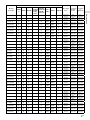
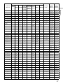
Speaker pattern
SPEAKERS terminals / PRE OUT jacks
Zone 2
connection
*
1
Front B
speaker
connection
*
1
Bi-amplifier
connection
*
1
FRONT A
CENTER SURROUND
SURROUND
BACK
(FRONT B/
BI-AMP/
ZONE 2)
(single)
SURROUND
BACK
(FRONT B/
BI-AMP/
ZONE 2)
(L/R)
HEIGHT 1
(ZONE 2)
HEIGHT 2
SUBWOOFER
5.0.4 (SB+TF+TM)
-
-
(TF) (TM)
-
Only PRE OUT Not available Not available
5.0.4 (SB+TF+TR)
-
-
(TF) (TR)
-
Only PRE OUT Not available Not available
5.0.4 (SB+TF+RH)
-
-
(TF) (RH)
-
Only PRE OUT Not available Not available
5.0.4 (SB+TM+TR)
-
-
(TM) (TR)
-
Only PRE OUT Not available Not available
5.0.4 (SB+TM+RH)
-
-
(TM) (RH)
-
Only PRE OUT Not available Not available
5.0.4 (SB+FD+SRD)
-
-
(FD) (SRD)
-
Only PRE OUT Not available Not available
5.1 (SB)
-
- - -
H1
Not available Not available
5.1.2 (SB+FH)
-
-
(FH)
-
Only PRE OUT Not available Not available
5.1.2 (SB+TM)
-
-
(TM)
-
Only PRE OUT Not available Not available
5.1.2 (SB+FD)
-
-
(FD)
-
Only PRE OUT Not available Not available
5.1.2 (SB+SRD)
-
-
(SRD)
-
Only PRE OUT Not available Not available
5.1.4 (SB+FH+TM)
-
-
(FH) (TM)
Only PRE OUT Not available Not available
5.1.4 (SB+FH+TR)
-
-
(FH) (TR)
Only PRE OUT Not available Not available
5.1.4 (SB+FH+RH)
-
-
(FH) (RH)
Only PRE OUT Not available Not available
5.1.4 (SB+TF+TM)
-
-
(TF) (TM)
Only PRE OUT Not available Not available
5.1.4 (SB+TF+TR)
-
-
(TF) (TR)
Only PRE OUT Not available Not available
5.1.4 (SB+TF+RH)
-
-
(TF) (RH)
Only PRE OUT Not available Not available
5.1.4 (SB+TM+TR)
-
-
(TM) (TR)
Only PRE OUT Not available Not available
5.1.4 (SB+TM+RH)
-
-
(TM) (RH)
Only PRE OUT Not available Not available
5.1.4 (SB+FD+SRD)
-
-
(FD) (SRD)
Only PRE OUT Not available Not available
6.0 (SB)
- - - - H1
Not available Not available
6.0.2 (SB+FH)
-
(FH)
- -
Only PRE OUT Not available Not available
6.0.2 (SB+TM)
-
(TM)
- -
Only PRE OUT Not available Not available
6.0.2 (SB+FD)
-
(FD)
- -
Only PRE OUT Not available Not available
6.0.2 (SB+SRD)
-
(SRD)
- -
Only PRE OUT Not available Not available
6.0.4 (SB+FH+TM)
-
(FH) (TM)
-
Only PRE OUT Not available Not available
6.0.4 (SB+FH+TR)
-
(FH) (TR)
-
Only PRE OUT Not available Not available
6.0.4 (SB+FH+RH)
-
(FH) (RH)
-
Only PRE OUT Not available Not available
6.0.4 (SB+TF+TM)
-
(TF) (TM)
-
Only PRE OUT Not available Not available
6.0.4 (SB+TF+TR)
-
(TF) (TR)
-
Only PRE OUT Not available Not available
6.0.4 (SB+TF+RH)
-
(TF) (RH)
-
Only PRE OUT Not available Not available
6.0.4 (SB+TM+TR)
-
(TM) (TR)
-
Only PRE OUT Not available Not available
6.0.4 (SB+TM+RH)
-
(TM) (RH)
-
Only PRE OUT Not available Not available
6.0.4 (SB+FD+SRD)
-
(FD) (SRD)
-
Only PRE OUT Not available Not available
6.1 (SB)
- - -
H1
Not available Not available
6.1.2 (SB+FH)
-
(FH)
-
Only PRE OUT Not available Not available
6.1.2 (SB+TM)
-
(TM)
-
Only PRE OUT Not available Not available
6.1.2 (SB+FD)
-
(FD)
-
Only PRE OUT Not available Not available
6.1.2 (SB+SRD)
-
(SRD)
-
Only PRE OUT Not available Not available
6.1.4 (SB+FH+TM)
-
(FH) (TM)
Only PRE OUT Not available Not available
6.1.4 (SB+FH+TR)
-
(FH) (TR)
Only PRE OUT Not available Not available
6.1.4 (SB+FH+RH)
-
(FH) (RH)
Only PRE OUT Not available Not available
6.1.4 (SB+TF+TM)
-
(TF) (TM)
Only PRE OUT Not available Not available
6.1.4 (SB+TF+TR)
-
(TF) (TR)
Only PRE OUT Not available Not available
6.1.4 (SB+TF+RH)
-
(TF) (RH)
Only PRE OUT Not available Not available
6.1.4 (SB+TM+TR)
-
(TM) (TR)
Only PRE OUT Not available Not available
6.1.4 (SB+TM+RH)
-
(TM) (RH)
Only PRE OUT Not available Not available
6.1.4 (SB+FD+SRD)
-
(FD) (SRD)
Only PRE OUT Not available Not available
6.0
-
-
- - - H1
Not available Not available
6.0.2 (FH)
-
-
(FH)
- -
Only PRE OUT Not available Not available
6.0.2 (TM)
-
-
(TM)
- -
Only PRE OUT Not available Not available
6.0.2 (FD)
-
-
(FD)
- -
Only PRE OUT Not available Not available
6.0.2 (SRD)
-
-
(SRD)
- -
Only PRE OUT Not available Not available

16
GB
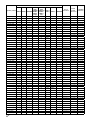
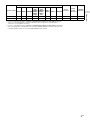
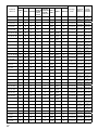
Speaker pattern
SPEAKERS terminals / PRE OUT jacks
Zone 2
connection
*
1
Front B
speaker
connection
*
1
Bi-amplifier
connection
*
1
FRONT A
CENTER SURROUND
SURROUND
BACK
(FRONT B/
BI-AMP/
ZONE 2)
(single)
SURROUND
BACK
(FRONT B/
BI-AMP/
ZONE 2)
(L/R)
HEIGHT 1
(ZONE 2)
HEIGHT 2
SUBWOOFER
6.0.2 (SBD)
-
-
(SBD)
- -
Only PRE OUT Not available Not available
6.0.4 (FH+TM)
-
-
(FH) (TM)
-
Only PRE OUT Not available Not available
6.0.4 (FH+TR)
-
-
(FH) (TR)
-
Only PRE OUT Not available Not available
6.0.4 (FH+RH)
-
-
(FH) (RH)
-
Only PRE OUT Not available Not available
6.0.4 (TF+TM)
-
-
(TF) (TM)
-
Only PRE OUT Not available Not available
6.0.4 (TF+TR)
-
-
(TF) (TR)
-
Only PRE OUT Not available Not available
6.0.4 (TF+RH)
-
-
(TF) (RH)
-
Only PRE OUT Not available Not available
6.0.4 (TM+TR)
-
-
(TM) (TR)
-
Only PRE OUT Not available Not available
6.0.4 (TM+RH)
-
-
(TM) (RH)
-
Only PRE OUT Not available Not available
6.0.4 (FD+SBD)
-
-
(FD) (SBD)
-
Only PRE OUT Not available Not available
6.1
-
-
- -
H1
Not available Not available
6.1.2 (FH)
-
-
(FH)
-
Only PRE OUT Not available Not available
6.1.2 (TM)
-
-
(TM)
-
Only PRE OUT Not available Not available
6.1.2 (FD)
-
-
(FD)
-
Only PRE OUT Not available Not available
6.1.2 (SRD)
-
-
(SRD)
-
Only PRE OUT Not available Not available
6.1.2 (SBD)
-
-
(SBD)
-
Only PRE OUT Not available Not available
6.1.4 (FH+TM)
-
-
(FH) (TM)
Only PRE OUT Not available Not available
6.1.4 (FH+TR)
-
-
(FH) (TR)
Only PRE OUT Not available Not available
6.1.4 (FH+RH)
-
-
(FH) (RH)
Only PRE OUT Not available Not available
6.1.4 (TF+TM)
-
-
(TF) (TM)
Only PRE OUT Not available Not available
6.1.4 (TF+TR)
-
-
(TF) (TR)
Only PRE OUT Not available Not available
6.1.4 (TF+RH)
-
-
(TF) (RH)
Only PRE OUT Not available Not available
6.1.4 (TM+TR)
-
-
(TM) (TR)
Only PRE OUT Not available Not available
6.1.4 (TM+RH)
-
-
(TM) (RH)
Only PRE OUT Not available Not available
6.1.4 (FD+SBD)
-
-
(FD) (SBD)
Only PRE OUT Not available Not available
7.0
-
- - - H1
Not available Not available
7.0.2 (FH)
-
(FH)
- -
Only PRE OUT Not available Not available
7.0.2 (TM)
-
(TM)
- -
Only PRE OUT Not available Not available
7.0.2 (FD)
-
(FD)
- -
Only PRE OUT Not available Not available
7.0.2 (SRD)
-
(SRD)
- -
Only PRE OUT Not available Not available
7.0.2 (SBD)
-
(SBD)
- -
Only PRE OUT Not available Not available
7.0.4 (FH+TM)
-
(FH) (TM)
-
Only PRE OUT Not available Not available
7.0.4 (FH+TR)
-
(FH) (TR)
-
Only PRE OUT Not available Not available
7.0.4 (FH+RH)
-
(FH) (RH)
-
Only PRE OUT Not available Not available
7.0.4 (TF+TM)
-
(TF) (TM)
-
Only PRE OUT Not available Not available
7.0.4 (TF+TR)
-
(TF) (TR)
-
Only PRE OUT Not available Not available
7.0.4 (TF+RH)
-
(TF) (RH)
-
Only PRE OUT Not available Not available
7.0.4 (TM+TR)
-
(TM) (TR)
-
Only PRE OUT Not available Not available
7.0.4 (TM+RH)
-
(TM) (RH)
-
Only PRE OUT Not available Not available
7.0.4 (FD+SBD)
-
(FD) (SBD)
-
Only PRE OUT Not available Not available
7.1
-
- -
H1
Not available Not available
7.1.2 (FH)
-
(FH)
-
Only PRE OUT Not available Not available
7.1.2 (TM)
-
(TM)
-
Only PRE OUT Not available Not available
7.1.2 (FD)
-
(FD)
-
Only PRE OUT Not available Not available
7.1.2 (SRD)
-
(SRD)
-
Only PRE OUT Not available Not available
7.1.2 (SBD)
-
(SBD)
-
Only PRE OUT Not available Not available
7.1.4 (FH+TM)
-
(FH) (TM)
Only PRE OUT Not available Not available
7.1.4 (FH+TR)
-
(FH) (TR)
Only PRE OUT Not available Not available
7.1.4 (FH+RH)
-
(FH) (RH)
Only PRE OUT Not available Not available
7.1.4 (TF+TM)
-
(TF) (TM)
Only PRE OUT Not available Not available
7.1.4 (TF+TR)
-
(TF) (TR)
Only PRE OUT Not available Not available
7.1.4 (TF+RH)
-
(TF) (RH)
Only PRE OUT Not available Not available
7.1.4 (TM+TR)
-
(TM) (TR)
Only PRE OUT Not available Not available

17
GB
Connections
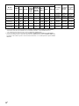
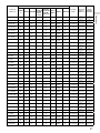
Speaker pattern
SPEAKERS terminals / PRE OUT jacks
Zone 2
connection
*
1
Front B
speaker
connection
*
1
Bi-amplifier
connection
*
1
FRONT A
CENTER SURROUND
SURROUND
BACK
(FRONT B/
BI-AMP/
ZONE 2)
(single)
SURROUND
BACK
(FRONT B/
BI-AMP/
ZONE 2)
(L/R)
HEIGHT 1
(ZONE 2)
HEIGHT 2
SUBWOOFER
7.1.4 (TM+RH)
-
(TM) (RH)
Only PRE OUT Not available Not available
7.1.4 (FD+SBD)
-
(FD) (SBD)
Only PRE OUT Not available Not available
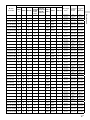
* If you are connecting speakers to SPEAKERS SURROUND BACK (FRONT B/BI-AMP/ZONE 2) terminals,
select one of the following three connection methods: “Zone 2 connection,” “front B speaker
connection,” or “bi-amplifier connection.”
* If you are connecting speakers to SPEAKERS SURROUND BACK (FRONT B/BI-AMP/ZONE 2) terminals for
Zone 2, front B speaker or bi-amplifier connection, the SPEAKERS HEIGHT 2 terminals cannot be used
for height speakers. In this case, use the PRE OUT HEIGHT 2 jacks instead.

18
GB
Settings
Setting up the receiver
Activating the network standby mode
You can keep the network function active even when the
receiver is in standby mode.
1 Select [Setup] - [Network Setup] - [Network
Standby] from the home menu.
2 Select [On].
Note
•When the receiver is in standby mode, the (power) indicator on
the front panel lights up in amber if [Network Standby] is set to
[On].
Turning on the control mode to make an
external controller connection
You can control the receiver from external devices.
1 Select [Setup] - [Install Setup] - [External Control]
from the home menu.
2 Select [On].
Note
•Set [External Control] to [On] to activate the network connection or
to activate control from an external controller connected to the
RS232C port.
Outputting a test tone from each speaker
(TestTone)
You can output a test tone from each speaker in sequence.
1 Select [Setup] - [Speaker Setup] - [Test Tone]
from the home menu.
2 Select the setting you want.
Off
Auto: The test tone is output from each speaker in
sequence.
Front L, Center, Front R, Surround R, Sur Back R, Sur
Back*, Sur Back L, Surround L, Height1 L, Height1 R,
Height2 R, Height2 L, Subwoofer: You can select which
speakers will output the test tone.
* [Sur Back] appears when only one surround back speaker is
connected.
3 Adjust the speaker level.
Tips
•You can set a test tone by pressing the TEST TONE button on the
remote control. In this case, you can only use the display panel for
the operation.
•To adjust the level of all speakers at the same time, press +/–.
You can also use MASTER VOLUME on the receiver.
•The adjusted value is shown on the TV screen while adjusting.
Displaying a test screen (Test Picture)
Display a test screen for HDMI OUT A and HDMI OUT B jacks.
1 Press TEST PICTURE on the remote control.
Tips
•A test picture is output in 480p from both the HDMI OUT A and
HDMI OUT B jack.
If you want to output a test picture in another resolution, select
[Setup] - [Install Setup] - [Test Picture for HDMI Out A] or [Test
Picture for HDMI Out B] from the home menu, and then select the
resolution setting you want.
•HDMI audio signals are not output while the test screen is
displayed.
Adjusting the sound balance automatically
(Auto Calibration)
This receiver is equipped with a D.C.A.C. (Digital Cinema
Auto Calibration) function, which allows you to perform
automatic calibration.
Auto Calibration allows you to perform automatic calibration
as follows.
– Check the connection between each speaker and the
receiver.
– Adjust the speaker level.
– Measure the distance of each speaker from your seating
position.*
– Measure the speaker size.*
– Measure the frequency characteristics (EQ).*
– Measure the frequency characteristics (Phase).* *
* The measurement result is not utilized when [Direct] is selected.
* The measurement result may be not utilized, depending on the
audio formats.
Note
•The D.C.A.C. is designed to achieve proper sound balance for your
room. However, you can adjust the speaker levels manually
according to your preference using Test Tone.
1 Set up each speaker correctly, and then connect
the optimizer microphone.
2 Select [Setup] - [Speaker Setup] - [Auto
Calibration] from the home menu.
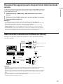
3 Follow the instructions on the TV screen, then
press to select [Start].
The measurement starts in 5seconds.
The measurement process will take approximately
30seconds with a test tone.
When the measurement ends, a beep sounds and the
screen switches.
4 Select the item you want.
Save: Saves the measurement results and exits the
setting process.
Retry: Performs the Auto Calibration again.
Discard: Exits the setting process without saving the
measurement results.
5 Save the measurement results.
Select [Save] in step4.

19
GB
Settings
Calibration Matching
When Auto Calibration is executed, this function works
automatically to match the distance and level of the right
and left speakers. You can set this function only after the
D.C.A.C. measurement process has been completed and the
results of D.C.A.C. measurement are saved. The setting is
valid until you change it.
Note
•If an error code or warning message appears on the screen in
step3, see “List of messages after Auto Calibration measurements”
(page 19).
Tips
•You can also perform automatic calibration by pressing the AUTO
CAL button on the remote control. If you use the AUTO CAL button,
the following restrictions apply to the operation:
– Prior settings relating to the Auto Calibration will be skipped.
– You can only use the display panel for the operation.
•The Auto Calibration function will be canceled if you perform the
following during the measurement process:
– Turn the receiver on or off.
– Press the input buttons on the remote control or on the receiver.
– Press .
– Press SPEAKERS on the receiver.
– Press HDMI OUTPUT.
– Press AMP MENU.
– Press HOME.
– Press AUTO CAL.
– Change the volume level.
List of messages after Auto Calibration
measurements
•Code 31:
Front speakers are not selected properly. Select the front
speakers using SPEAKERS, and then perform Auto
Calibration again.
•Code 32, Code 33:
– Speakers were not detected or not connected properly.
– None of the front speakers are connected or only one front
speaker is connected.
– Either the surround left or surround right speaker is not
connected.
– A surround back speaker is connected only to the SPEAKERS
SURROUND BACK (FRONT B/BI-AMP/ZONE 2) R terminal. If
connecting only one surround back speaker, connect it to
the SPEAKERS SURROUND BACK (FRONT B/BI-AMP/ZONE 2)
L terminal.
– Either the Height1 left or Height1 right speaker is not
connected.
– Either the Height2 left or Height2 right speaker is not
connected.
– The optimizer microphone is not connected. Make sure that
the optimizer microphone is connected properly, and then
perform Auto Calibration again.
If the optimizer microphone is connected properly but the
error code still appears, the optimizer microphone cable
may be damaged.
•Code 34:
Speakers are not placed in the proper position. Speakers or
an optimizer microphone on the right or left may be placed
wrongly. See the supplied Startup Guide and check the
speaker position.
•Code 35:
The measurement result is not match to the speaker
pattern you set. See the Help Guide and change the setting
to fit the actual speaker pattern.
•Warning 40:
The measurement process has been completed and a high
noise level has been detected. You may be able to achieve
better results if you try the process again in a quiet
environment.
•Warning 41, Warning 42:
– The input from the optimizer microphone is too large.
– The distance between the speaker and the microphone may
be too small. Set them further apart and perform the
measurement again.
•Warning 43:
The distance and position of a subwoofer cannot be
detected. This may be caused by noise. Try performing the
measurement in a quiet environment.
•Warning 44:
Measurement has been completed. However the speakers
are not placed in the proper position with respect to each
other. See the supplied Startup Guide and check the
relative positions of the speakers.
•NO WARNING:
There is no warning information.
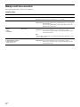
Saving/loading settings of the receiver
You can save the settings to a USB flash drive and restore
the saved settings to the receiver or to another receiver of
the same model.
Saving Loading
To save the settings
Insert a USB flash drive to the USB port on the front panel of
the receiver.
Select [Setup] - [Install Setup] - [Save/Load] - [Save] from the
home menu.
To load the settings
Insert to the USB port on the front panel of the receiver a
USB flash drive on which the settings are saved.
Select [Setup] - [Install Setup] - [Save/Load] - [Load] from the
home menu.

20
GB
Linking with a Hi-Fi music system
This receiver can switch its power and input automatically by
linking with playback operation of the Hi-Fi music system.
Configure settings to enable the receiver to operate linked
with a Hi-Fi System device.
1 Select [Setup] - [Network Setup] - [Music
Connect] from the home.
2 Select the setting you want.
Each of the following settings can be selected on both
Device 1 and Device 2.
Connected Device: Select the connected device to
enable the function.
Input for Music Connect1 or 2: Select the input to link
with.
Preset Volume: Preset the volume level.
Output Zone: Select the zone to which you want to
output sound.
3 Start playback on the player device.
The receiver will be turned on and the input will be
switched automatically.
To disable Music Connect
Select [Setup] - [Network Setup] - [Music Connect] -
[Connected Device] - [Remove Connected Device] from the
home menu.
Notes
•The Music Connect feature can be linked only with the power
source and input of the main zone or Zone 2. This feature does not
link with Zone 3.
•The link feature of Music Connect may not work correctly
depending on factors such as the specifications of the connected
device.
•We recommend that you set [Network Standby] to [On] to activate
the feature for linking with Music Connect even if the receiver is in
standby mode.
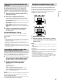
Mixing separate audio/video inputs (Last
video mode)
The receiver can continuously output the input video image
used most recently when an audio-only input source is
selected.
1 Connect the desired background music source to
an input by analog, optical, or coaxial cable. Or
use the built-in tuner.
2 Set the input to the following in the Input Setup
menu.
HDMI: [None]
Component: [None]
Composite: [---]
Audio: The input connected to the source.
When using the built-in tuner, set the screen mode to
[Simple] using the options menu in [FM/AM Display].
Example
Press SAT/CATV followed by TUNER to listen to sound from
the built-in tuner while watching a video source connected
to SAT/CATV.
The audio output changes to that of the tuner source while
SAT/CATV video output is retained.
Setting the in-ceiling speaker mode
Sony has developed a new special sound mode for CI
installation. This feature will virtually relocate the front and
center in-ceiling speakers down to around the screen. That
way, the customer will hear the actors’ voices coming from
the screen instead of the ceiling. This mode also makes
music sound more natural in a room with in-ceiling speakers.
1 Perform Auto Calibration.
2 Select [Setup] - [Audio Setup] - [In-Ceiling
Speaker Mode] - [Front & Center] or [Front] from
the home menu.
Notes
•This mode is not available when [Pure Direct] is set to [On].
•This mode will be disabled in a speaker pattern with Dolby
Enabled speakers.
Tips
•You can select on/off for each input in Input Setup menu.
•You can also select [In-Ceiling Speaker Mode] in [Sound Effects]
from the home menu.
•You can also switch the function on/off by pressing IN-CEILING SP
on the remote control or the receiver.
•To obtain optimal effects in the listening environment, configure
the [Ceiling Height] setting and perform Auto Calibration.
La page est en cours de chargement...
La page est en cours de chargement...
La page est en cours de chargement...
La page est en cours de chargement...
La page est en cours de chargement...
La page est en cours de chargement...
La page est en cours de chargement...
La page est en cours de chargement...
La page est en cours de chargement...
La page est en cours de chargement...
La page est en cours de chargement...
La page est en cours de chargement...
La page est en cours de chargement...
La page est en cours de chargement...
La page est en cours de chargement...
La page est en cours de chargement...
La page est en cours de chargement...
La page est en cours de chargement...
La page est en cours de chargement...
La page est en cours de chargement...
La page est en cours de chargement...
La page est en cours de chargement...
La page est en cours de chargement...
La page est en cours de chargement...
La page est en cours de chargement...
La page est en cours de chargement...
La page est en cours de chargement...
La page est en cours de chargement...
La page est en cours de chargement...
La page est en cours de chargement...
La page est en cours de chargement...
La page est en cours de chargement...
La page est en cours de chargement...
La page est en cours de chargement...
La page est en cours de chargement...
La page est en cours de chargement...
La page est en cours de chargement...
La page est en cours de chargement...
La page est en cours de chargement...
La page est en cours de chargement...
La page est en cours de chargement...
La page est en cours de chargement...
La page est en cours de chargement...
La page est en cours de chargement...
La page est en cours de chargement...
La page est en cours de chargement...
La page est en cours de chargement...
La page est en cours de chargement...
La page est en cours de chargement...
La page est en cours de chargement...
La page est en cours de chargement...
La page est en cours de chargement...
La page est en cours de chargement...
La page est en cours de chargement...
La page est en cours de chargement...
La page est en cours de chargement...
La page est en cours de chargement...
La page est en cours de chargement...
La page est en cours de chargement...
La page est en cours de chargement...
-
 1
1
-
 2
2
-
 3
3
-
 4
4
-
 5
5
-
 6
6
-
 7
7
-
 8
8
-
 9
9
-
 10
10
-
 11
11
-
 12
12
-
 13
13
-
 14
14
-
 15
15
-
 16
16
-
 17
17
-
 18
18
-
 19
19
-
 20
20
-
 21
21
-
 22
22
-
 23
23
-
 24
24
-
 25
25
-
 26
26
-
 27
27
-
 28
28
-
 29
29
-
 30
30
-
 31
31
-
 32
32
-
 33
33
-
 34
34
-
 35
35
-
 36
36
-
 37
37
-
 38
38
-
 39
39
-
 40
40
-
 41
41
-
 42
42
-
 43
43
-
 44
44
-
 45
45
-
 46
46
-
 47
47
-
 48
48
-
 49
49
-
 50
50
-
 51
51
-
 52
52
-
 53
53
-
 54
54
-
 55
55
-
 56
56
-
 57
57
-
 58
58
-
 59
59
-
 60
60
-
 61
61
-
 62
62
-
 63
63
-
 64
64
-
 65
65
-
 66
66
-
 67
67
-
 68
68
-
 69
69
-
 70
70
-
 71
71
-
 72
72
-
 73
73
-
 74
74
-
 75
75
-
 76
76
-
 77
77
-
 78
78
-
 79
79
-
 80
80


Sony STR-ZA5000ES Guide d'installation
- Catégorie
- Récepteurs AV
- Taper
- Guide d'installation
dans d''autres langues
Documents connexes
-
Sony STR-ZA3100ES Manuel utilisateur
-
Sony STR-ZA810ES Guide d'installation
-
Sony STR-ZA5000ES Guide de démarrage rapide
-
-
Sony STR-ZA2000ES Guide de démarrage rapide
-
-
Sony STR-ZA1100ES Guide de démarrage rapide
-
-