

2
ENGLISH
2
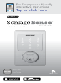
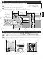
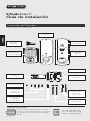
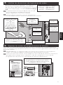
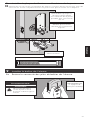
Installation Instructions
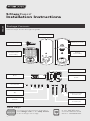
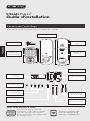
Package Contents
Camelot Style shown throughout guide.
Need Help?
For technical documents and videos,
visit schlage.com or the Help Center
in the Schlage Sense app.
U.S.A.: 888-805-9837
Canada: 800-997-4734
Mexico: 018005067866
Touchscreen
Assembly
Battery Cover
Reinforcement
Plate
Reinforcement
Screws (2)
Strike
Bolt/Strike Screws
(4)
Bolt
Set Screw
Backup Key
Alarm
Assembly
Support Plate
Support Plate
Screws (2)
Alarm Assembly
Screw

3
ENGLISH
Let’s get started!
Once you have all your tools together, please follow each step carefully and in order.
Because this is an electronic lock, the order of steps is very important. If you skip a step,
you may have to perform a factory default reset and start over.
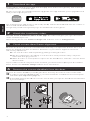
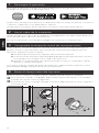
You will denitely need this tool:
• Phillips screwdriver
You can use a manual or electric
screwdriver, but please DO NOT use a
power drill!
You may also need these tools:
• Tape Measure
• Flathead Screwdriver
• Pencil
• Wood Block
• Hammer
INSTALLATION NOTES! PLEASE READ!
• DO NOT use a power drill for installation! This could damage the lock.
• Please read all the instructions before calling customer support.
• DO NOT install the batteries before installing the lock! Follow the instructions in
order!
• If you have previously installed this lock on another door, you MUST perform a
Factory Default Reset FIRST! See the User Guide for more information.
• This lock is designed for the following operating temperatures:
• Outside Lock Body (exterior mounted): -31˚F (-35˚C) to 151˚F (66˚C)
• Inside Lock Body (interior mounted): 14˚F (-10˚C) to 120˚F (49˚C)
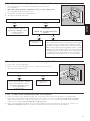
Steps at a Glance
1 Download the app. ................................................................................................................ 4
2 Watch the installation video. ................................................................................................. 4
3 Check current door/frame alignment. .................................................................................. 4
4 Remove the current deadbolt from the door. ...................................................................... 4
5 Check door/frame dimensions.............................................................................................. 5
6 Locate programming and access codes. ............................................................................. 5
7 Install bolt and strike. ............................................................................................................. 6
7a Adjust bolt length, if necessary. ..................................................................................... 6
7b Change the faceplate, if necessary. ............................................................................... 6
7c Install the bolt into the door. ......................................................................................... 7
7d Install the strike into the frame. ..................................................................................... 7
7e Test bolt alignment. ........................................................................................................8
8 Install the Touchscreen Assembly. ........................................................................................ 8
8a Install the Touchscreen on the outside of the door. ....................................................8
8b Install the Support Plate on the inside of the door. ..................................................... 9
9 Install the Alarm Assembly..................................................................................................... 9
9a Remove the battery cover from the Alarm Assembly. .................................................9
9b Connect the cable to the Alarm Assembly. ................................................................ 10
9c Install the Alarm Assembly. .......................................................................................... 10
9d Secure the Alarm Assembly to the Support Plate. .....................................................11
10 Install the Batteries. .............................................................................................................. 11
10a Install the batteries into the battery tray. .................................................................... 11
10b Install the battery cover. ...............................................................................................12
11 Set up the Lock. .................................................................................................................... 12
12 Test the Lock. ........................................................................................................................ 12
12a Extend the bolt (lock) using the inside thumbturn. ...................................................12
12b Extend the bolt (lock) using the Touchscreen. ...........................................................13
12c Retract the bolt (unlock) using the Touchscreen. ....................................................... 13
12d If the lock failed to lock or unlock: .............................................................................. 13
13 Continue to the User Guide. ............................................................................................... 15

4
ENGLISH
1 Download the app.
Download the Schlage Sense app from the App Store and on Google Play. Just search for
“Schlage Sense” to nd the app.
Be sure to accept any available rmware upgrades. The app will alert you to upgrades and
walk you through the process.
The Schlage Sense app works on iPhone®, iPad®, and iPod touch® with iOS 9.3 or later or
devices with Android 5.0 or later.
Google Play and the Google Play logo are trademarks of Google Inc.
2 Watch the installation video.
You can access installation videos in the app! The videos will give you a good overview
of the installation process.
Alternatively, please visit answers.schlage.com and then click on Schlage Sense.
3 Check current door/frame alignment.
Because the bolt on this lock is extended automatically, it is important that the door and
frame are aligned. Use this checklist to determine if your current alignment will work
without any adjustment.
I can lock the door without pushing, pulling or lifting the door.
My door alignment—the ability to lock the door easily and smoothly—stays the
same with changing seasons.
When the door is closed, there is space for the deadbolt to extend 1” into the frame
when locked.
If you could not check every box in the checklist, you will need to adjust your door and/or
frame. Please visit answers.schlage.com for more information.
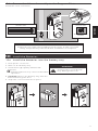
4 Remove the current deadbolt from the door.
Remove the entire deadbolt, including the bolt. You may also want to remove the strike.
»
In order to maintain BHMA Grade 1, you must install the included reinforcement plate
and strike (see step 7d on page 7).
»
A standard Schlage deadbolt is shown. Check with your specic deadbolt manufacturer
if you need help.

5
ENGLISH
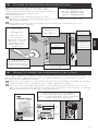
5 Check door/frame dimensions.
Measure the dimensions shown. If your door dimensions
do not match, you will need to change your door
preparation. Go to answers.schlage.com
for drilling instructions.
»
If your door is thicker than 1C\v”, you will need a
thick door kit. Please call Customer Service:
»
Mark your crossbore and backset measurements on this page. You will need these
measurements for installation. Either measurement is normal.
Backset
2C\,” (60 mm)
OR
2C\v” (70 mm)
Minimum 5"
(127 mm)
This lever represents
your current knob or
lever, which may be
already installed.
Door Thickness
1C\,” to 1C\v”
Crossbore
Diameter
2Z\,” (53 mm)
OR
1Z\x" (38 mm)
If your crossbore is
1Z\x”, see
Removing Spacer
on page 14.
1” (25 mm)
Hole
Door Stop
Hole at least
1” (25 mm)
deep.
6 Locate programming and access codes.
Codes are located on the stickers on the front of the User Guide. You will need these
codes to operate the lock. They are also located on the back of the Alarm Assembly.
»
Do NOT remove these stickers from the back of your lock! If you lose your codes, you
can reset your lock back to these default codes.
»
To connect your lock to your iOS or Android phone, follow the instructions in the
Schlage Sense app. You will use the HomeKit™ setup code or the Programming Code
to complete pairing.
PLEASE KEEP
THIS GUIDE
You will need
these codes to
operate your lock!
CONSERVE
ESTA GUÍA
¡Necesitará
estos códigos
para operar la
cerradura!
VEUILLEZ
CONSERVERCE
GUIDE
Vous aurez besoin de
ces codes pour faire
fonctionner la serrure!
User Guide
Default Codes
Códigos de predeterminado
Codes du défaut
Place Label Here
Poner la etiqueta aquí
Placer l’autocollant ici
Setup Code
Código de configuración
Code de configuration
Place Label Here
Poner la etiqueta aquí
Placer l’autocollant ici
0000000
XXX-XX-XXX
0000000
XXX-XX-XXX
0000000
XXX-XX-XXX
One label has your default Programming
and access codes. The other label has your
HomeKit setup code.
Toll-Free Calling From:
U.S.A.: (888) 805-9837
Canada: (800) 997-4734
Mexico: 018005067866

6
ENGLISH
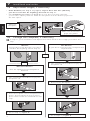
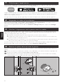
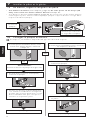
7 Install bolt and strike.
7a Adjust bolt length, if necessary.
• If the backset (see step 5 on page 5) of your door was 2C\,” (60 mm),
you do not need to do anything. Proceed to step 7b.
• If the backset (see step 5 on page 5) of your door was 2C\v” (70 mm),
you need to adjust your bolt. Twist the faceplate until the button pops into
the 2C\v” space.
Twist the
faceplate.
Make sure the button
pops into place.
7b Change the faceplate, if necessary.
»
In step 7c, your installation will depend on which kind of door edge you had in this
step.
No Mortise
If your door looks like this, complete the
steps below.
1. Use a athead screwdriver to pry the
faceplate off.
2. Remove the backplate.
Mortise
If your door looks like this, you don’t
need to do anything. Go to step 7c.
OR
Alternate Mortise
Use the square-corner faceplate if
desired.
1. Use a athead screwdriver to pry the
faceplate off.
OR
2. Press the square-corner faceplate into
place. The faceplate may not stay in
place until screws are installed in next
step.
4. Go to step 7c, Figure B.
3. Go to step 7c, Figure A.
3. Slide the round faceplate into place.

7
ENGLISH
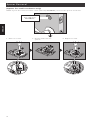
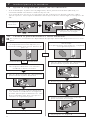
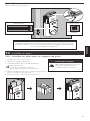
7c Install the bolt into the door.
Choose the picture below that matches your door.
FIgure A: Mortise
Figure B: No Mortise
Use a block of wood and
a hammer (not included)
to tap the bolt into place.
You don’t need to use the
screws.
Actual Size (2)
OR
Make sure
the word
TOP faces
up when
installing
the bolt.
7d Install the strike into the frame.
Install all the parts shown for maximum security.
»
In order to maintain BHMA Grade 1, you must install the included reinforcement plate
and strike.
Actual Size (2)
Reinforcement Screws: Actual Size (2)
Door Stop
Make sure this hole
is at least 1” (25
mm) deep.
»
The reinforcement screws may not t on doors with sidelights.

8
ENGLISH
7e Test bolt alignment.
1. Close the door.
2. Insert a athead screwdriver into the slot in the bolt, as shown.
3. Rotate the screwdriver toward the door edge to extend the bolt into the hole in the
frame. This operation should be smooth. You should be able to rotate the screwdriver
90˚, fully extending the bolt.
4. If the operation was not smooth, or if the bolt did not fully extend, adjust your frame
and/or door preparation. Go to answers.schlage.com and watch the video Proper
Alignment of Door and Frame for a Smoothly Operating Lock for further instructions.
5. Retract (unlock) the bolt before continuing to step 8.
»
If the deadbolt continues to rub against the strike, contact Customer Support for an
alternate strike with an additional .060” (2 mm) clearance.
Retract the bolt
before continuing
to step 8.
CAUTION
Test from the inside to
avoid being locked out!
If you can rotate the
screwdriver a full 90˚,
then the bolt is fully
extended.
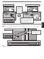
8 Install the Touchscreen Assembly.
8a Install the Touchscreen on the outside of the door.
Always remove the spacer for a 1Z\x” (38 mm) crossbore. See Spacer Removal on page
14 before continuing.
»
The clips snap into the crossbore (see step 5 on page 5) to assist in holding the
keypad on the door.
»
The Touchscreen Assembly should install smoothly. If it does not, check that the bolt is
set to the correct backset (see step 7a on page 6).
»
NOTE: If you have a crossbore (see step 5 on page 5) that is slightly less than 2Z\,”
(54 mm), the lock may not install smoothly. You can remove the spacer.
Clips snap into
the crossbore.
Align the tab
with the notch.
Route the cable
under the bolt.

9
ENGLISH
8b Install the Support Plate on the inside of the door.
»
Make sure the Touchscreen and Support Plate are straight on the door before
tightening the screws. Tighten screws fully to prevent the lock from moving over time.
TOP
Make sure the indented
circle is facing the door.
Hold the Touchscreen on
the outside of the door
while you tighten the
screws.
Actual Size (2)
TOP
Route the cable
through the slot.
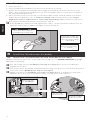
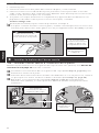
9 Install the Alarm Assembly.
9a Remove the battery cover from the Alarm Assembly.
DO NOT remove
the battery tray
(not shown)!
ELECTROSTATIC DISCHARGE
WARNING!
Touching the circuit board
may damage the lock!

10
ENGLISH
9b Connect the cable to the Alarm Assembly.
»
Locate the screws in step 9d before beginning this step so they will be handy when you
need them.
The connector ts only one
way. Match the dot on the
connector with the dot on the
circuit board.
9c Install the Alarm Assembly.
1. Align the tab with the notch as shown.
2. Route the cable into the channel.
3. Then slide the Alarm Assembly toward the door.
Align tab with
notch.
IMPORTANT!
Check that tab is
aligned with notch. If
not aligned, you may
have to remove the
whole lock and start
over.
Route the cable into
the channel to avoid
crimping the cable.

11
ENGLISH
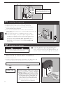
9d Secure the Alarm Assembly to the Support Plate.
Install the lower screw rst.
Actual Size
8-32 x .187 UP
FHMS
Actual Size
8-32 x 1Z\,”
NOTE
Please do not rotate the thumbturn at this time. It may not rotate
easily. Setup will be performed after installation is complete.
10 Install the Batteries.
10a Install the batteries into the battery tray.
1. Unsnap the connector.
2. Remove the battery tray.
3. Install four high-quality alkaline AA
batteries.
»
Lithium batteries may cause undesirable
operation.
4. Carefully replace the battery tray, with the
batteries facing the door.
5. Snap the connector back into place.
-
+
-
+
-
+
-
+
ELECTROSTATIC DISCHARGE
WARNING!
Touching the circuit board
may damage the lock!

12
ENGLISH
10b Install the battery cover.
Speaker Hole
DO NOT install screw!
11 Set up the Lock.
1. Open the door if it is not already open.
2. Press the Outside Schlage Button.
3. Enter one of the default access codes into the
lock (see label shown in step 6
on page 5).
4. The lock will perform a setup routine. Wait until
the bolt stops moving before continuing.
»
If the Touchscreen did not light up during this
step, you may have a power problem. Install
fresh batteries and make sure the battery wires
are connected (see step 10a on page 11).
If that does not help, make sure the cable is
connected and is not crimped (see step 9b on
page 10).
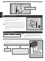
12 Test the Lock.
CAUTION
Keep the key with you during
testing to avoid being locked out!
»
For complete information about
programming and light/beep patterns,
see the Manual Programming Guide
and Troubleshooting sections in the User
Guide.
12a Extend the bolt (lock) using the inside thumbturn.
1. Close the door.
2. Rotate the thumbturn toward the door jamb to extend
the bolt.
Was this operation smooth?
Continue to
step 12b.
You may need to adjust your door/
frame. Continue to step 12b for
further testing, or go to answers.
schlage.com and watch the video
Proper Alignment of Door and
Frame for a Smoothly Operating
Lock for adjustment instructions.
NOYES

13
ENGLISH
10b Install the battery cover.
Speaker Hole
DO NOT install screw!
11 Set up the Lock.
1. Open the door if it is not already open.
2. Press the Outside Schlage Button.
3. Enter one of the default access codes into the
lock (see label shown in step 6
on page 5).
4. The lock will perform a setup routine. Wait until
the bolt stops moving before continuing.
»
If the Touchscreen did not light up during this
step, you may have a power problem. Install
fresh batteries and make sure the battery wires
are connected (see step 10a on page 11).
If that does not help, make sure the cable is
connected and is not crimped (see step 9b on
page 10).
12 Test the Lock.
CAUTION
Keep the key with you during
testing to avoid being locked out!
»
For complete information about
programming and light/beep patterns,
see the Manual Programming Guide
and Troubleshooting sections in the User
Guide.
12a Extend the bolt (lock) using the inside thumbturn.
1. Close the door.
2. Rotate the thumbturn toward the door jamb to extend
the bolt.
Was this operation smooth?
Continue to
step 12b.
You may need to adjust your door/
frame. Continue to step 12b for
further testing, or go to answers.
schlage.com and watch the video
Proper Alignment of Door and
Frame for a Smoothly Operating
Lock for adjustment instructions.
NOYES
12b Extend the bolt (lock) using the Touchscreen.
1. Unlock the door using the thumbturn if you have
not already.
2. Take the key and the default access codes with you!
Go outside and close the door.
3. Press the Outside Schlage Button.
4. The bolt should extend.
Alignment is
correct.
You need to adjust your
door/frame. Go to
answers.schlage.com
for adjustment
instructions.
YES
NO
The lock has both a low power and high
power mode. It will try low power rst
and then high power when unsuccessful.
After three times using high power, it will
always use the high power mode instead
of trying twice each time. You may want
to adjust your door/frame to conserve
battery power, but it is not necessary.
YES
NO
Did the bolt extend (is the door locked)?
Did the bolt take two tries to
extend?
Each try sounds like two
cycles.
12c Retract the bolt (unlock) using the Touchscreen.
1. Press the Schlage button.
2. Enter one of the default access codes into the lock.
3. The bolt should retract.
Alignment is
correct.
Use the key to unlock the
door. You need to adjust
your door/frame. Go to
answers.schlage.com
for adjustment
instructions.
YES
NO
Did the bolt retract (is the door unlocked)?
12d If the lock failed to lock or unlock:
1. If the Touchscreen did not light up, you may have a power problem. Install fresh
batteries and make sure the battery connector is connected (see step 10a on page
11). If that does not help, make sure the cable is connected to the Alarm Assembly
and is not crimped (see step 9b on page 10).
2. If the lock had power but you need to adjust your door/frame, please go online to
answers.schlage.com for complete adjustment instructions and videos.

14
ENGLISH
Spacer Removal
(Option for small crossbores only)
ONLY if your door has less than a 2Z\,” (54 mm) crossbore, remove the spacer as shown.
1. Remove screw. 2. Rotate and remove
spacer.
3. Replace screw.
Less than
2Z\," (54 mm)
Crossbore

15
ENGLISH
15
13 Continue to the User Guide.
Your lock is installed and functional. Continue to the User Guide for complete information
about how to congure and operate the lock and alarm.
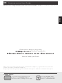
Questions about your new
Smart Deadbolt?
Please don’t return it to the store!
Let us help you rst!
Need Help?
For technical documents and
videos, visit schlage.com or
download the Schlage Sense app.
U.S.A.: 888-805-9837
Canada: 800-997-4734
Mexico: 018005067866
Apple, iPhone, iPad, iPad Air, and iPod touch are trademarks of Apple Inc., registered in the U.S. and other
countries. HomeKit is a trademark of Apple Inc.
Google Play and the Google Play logo are trademarks of Google Inc. Android is a trademark of Google Inc.


Guía de instalación
CERRADURA INTELIGENTE

1818
ESPAÑOL
Guía de instalación
Contenido del Paquete
Estilo Camelot en toda la guía
¿Necesita ayuda?
Para acceder a documentos y videos
técnicos, visite schlage.com o el Centro
de ayuda en la aplicación de Schlage
Sense.
EE. UU.: 888-805-9837
Canadá: 800-997-4734
México: 018005067866
Unidad de la
pantalla táctil
Cubierta de
la batería
Placa de
refuerzo
Tornillos de
refuerzo (2)
Cerradura
Tornillos del
perno/
cerradura (4)
Perno
Tornillo de ajuste
Clave de
respaldo
Unidad de la
alarma
Placa de
soporte
Tornillos de la
placa de
soporte (2)
Tornillo de la
unidad
de la alarma

19
ESPAÑOL
¡Comencemos!
Una vez que haya reunido todas sus herramientas, siga cada paso con atención y en orden.
Debido a que esta es una cerradura electrónica, el orden de los pasos es muy importante.
Si omite un paso, es probable que deba restablecer la conguración predeterminada de
fábrica y volver a comenzar.
Denitivamente, necesitará esta
herramienta:
• Destornillador Phillips
Puede usar un destornillador manual
o eléctrico, pero NO use un taladro
eléctrico.
También puede necesitar estas
herramientas:
• Cinta métrica
• Destornillador de punta plana
• Lápiz
• Bloque de madera
• Martillo
¡NOTAS DE INSTALACIÓN! ¡LÉALAS!
• ¡NO utilice un taladro eléctrico para la instalación! Esto podría dañar la cerradura.
• Lea todas las instrucciones antes de comunicarse con el servicio de asistencia al
cliente.
• ¡NO coloque las baterías antes de instalar la cerradura! ¡Siga las instrucciones en
orden!
• Si ya ha instalado esta cerradura en otra puerta, ¡PRIMERO DEBE restaurar la
conguración predeterminada de fábrica! Consulte la Guía del usuario para obtener
más información.
• Esta cerradura está diseñada para las siguientes temperaturas de funcionamiento:
• Fuera del cuerpo de la cerradura (montada en el exterior): -31˚ F (-35 ˚C) a 151
˚F (66 ˚C)
• Dentro del cuerpo de la cerradura (montada en el interior): 14˚ F (-10 ˚C) a 120
˚F (49 ˚C)
Breve descripción de los pasos
1 Descargue la aplicación. ...................................................................................................... 20
2 Vea el video de la instalación. ............................................................................................. 20
3 Compruebe la alineación actual de la puerta/marco. ...................................................... 20
4 Retire el cerrojo actual de la puerta. .................................................................................. 20
5 Consulte las dimensiones de la puerta/marco. ................................................................. 21
6 Ubique los códigos de programación y de usuario. ......................................................... 21
7 Instale el perno y la cerradura. ............................................................................................ 22
7a Ajuste la longitud del perno, de ser necesario. ......................................................... 22
7b Cambie la placa delantera si fuera necesario. ........................................................... 22
7c Instale el perno en la puerta. . ..................................................................................... 23
7d Instale la cerradura en el marco. ................................................................................. 23
7e Prueba la alineación del perno. ................................................................................... 24
8 Instale la unidad de la pantalla táctil. ................................................................................. 24
8a Instale la pantalla táctil en la parte externa de la puerta. ......................................... 24
8b Instale la placa de soporte en la parte interna de la puerta. .................................... 25
9 Instale la unidad de la alarma. ............................................................................................ 25
9a Retire la cubierta de la batería de la unidad de la alarma. ...................................... 25
9b Conecte el cable a la unidad de la alarma. ................................................................ 26
9c Instale la unidad de la alarma. ..................................................................................... 26
9d Sujete la unidad de la alarma a la placa de soporte. ................................................ 27
10 Instale las baterías. ............................................................................................................... 27
10a Instale las baterías en la bandeja de las baterías. ...................................................... 27
10b Instale la cubierta de las baterías. ............................................................................... 28
11 Congure la cerradura. ........................................................................................................ 28
12 Pruebe la cerradura. ............................................................................................................. 28
12a Extienda el perno (cerradura) usando el pestillo giratorio interior. .......................... 28
12b Extienda el perno (bloqueo) usando la pantalla táctil. .............................................. 29
12c Retraiga el perno (desbloqueo) usando la pantalla táctil. ........................................ 29
12d Si la cerradura no se bloqueó o desbloqueó: ............................................................ 29
13 Continúe con la Guía del usuario. ...................................................................................... 31

20
ESPAÑOL
1 Descargue la aplicación.
Descargue la aplicación Schlage Sense desde App Store y Google Play. Solo ingrese
«Schlage Sense» para encontrar la aplicación.
La aplicación Schlage Sense funciona en dispositivos iPhone, iPad y iPod Touch con iOS 9.3
o superior, o dispositivos con Android 5.0 o superior.
Google Play y el logotipo de Google Play son marcas comerciales de Google Inc.
2 Vea el video de la instalación.
¡Puede acceder a los videos de la instalación en la aplicación! Los videos le brindarán una
visión general sobre el proceso de instalación.
De manera alternativa, visite answers.schlage.com y haga clic en Schlage Sense.
3 Compruebe la alineación actual de la puerta/marco.
Como el perno en esta cerradura se extiende automáticamente, es importante que la
puerta y el marco estén alineados. Use esta lista de vericación para determinar si su
alineación actual funcionará sin ajustes.
Puedo bloquear la puerta sin empujar, tirar ni levantar la puerta.
La alineación de mi puerta (la posibilidad de bloquear la puerta de forma sencilla y
sin interrupciones) es igual con el cambio de estaciones.
Cuando se cierra la puerta, hay espacio para que el cerrojo se extienda 1” dentro
del marco cuando se bloquea.
Si no marcó todas las casillas de la lista de vericación, deberá ajustar su puerta o marco.
Visite answers.schlage.com para obtener más información.
4 Retire el cerrojo actual de la puerta.
Retire el cerrojo completo, incluido el perno. También puede retirar la cerradura.
»
Para mantener el grado 1 de BHMA, debe instalar la placa de refuerzo y la cerradura
incluidas (ver el paso 7d en la página 23).
»
Se muestra un cerrojo Schlage estándar. Consulte al fabricante de su cerrojo especíco
si necesita ayuda.
La page est en cours de chargement...
La page est en cours de chargement...
La page est en cours de chargement...
La page est en cours de chargement...
La page est en cours de chargement...
La page est en cours de chargement...
La page est en cours de chargement...
La page est en cours de chargement...
La page est en cours de chargement...
La page est en cours de chargement...
La page est en cours de chargement...
La page est en cours de chargement...
La page est en cours de chargement...
La page est en cours de chargement...
La page est en cours de chargement...
La page est en cours de chargement...
La page est en cours de chargement...
La page est en cours de chargement...
La page est en cours de chargement...
La page est en cours de chargement...
La page est en cours de chargement...
La page est en cours de chargement...
La page est en cours de chargement...
La page est en cours de chargement...
La page est en cours de chargement...
La page est en cours de chargement...
La page est en cours de chargement...
La page est en cours de chargement...
-
 1
1
-
 2
2
-
 3
3
-
 4
4
-
 5
5
-
 6
6
-
 7
7
-
 8
8
-
 9
9
-
 10
10
-
 11
11
-
 12
12
-
 13
13
-
 14
14
-
 15
15
-
 16
16
-
 17
17
-
 18
18
-
 19
19
-
 20
20
-
 21
21
-
 22
22
-
 23
23
-
 24
24
-
 25
25
-
 26
26
-
 27
27
-
 28
28
-
 29
29
-
 30
30
-
 31
31
-
 32
32
-
 33
33
-
 34
34
-
 35
35
-
 36
36
-
 37
37
-
 38
38
-
 39
39
-
 40
40
-
 41
41
-
 42
42
-
 43
43
-
 44
44
-
 45
45
-
 46
46
-
 47
47
-
 48
48


dans d''autres langues
- English: Schlage BE479 Operating instructions
- español: Schlage BE479 Instrucciones de operación
Documents connexes
-
Schlage FE469NX LAT 619 CEN Manuel utilisateur
-
Schlage FE469NX LAT 619 CEN Mode d'emploi
-
-
-
-
-
Schlage BE479AA V CAM 619 Manuel utilisateur
-
-
-