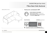
Dorel Home 4151639N Assembly Manual
- Catégorie
- Supports d'équipement audiovisuel
- Taper
- Assembly Manual

Date of Purchase
Lot Number (TAKEN FROM CARTON)
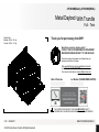
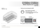
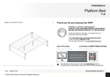
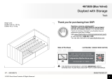
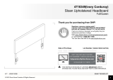
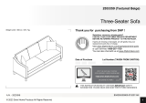
Thank you for purchasing from DHP!
THIS INSTRUCTION BOOKLET CONTAINS IMPORTANT SAFETY
INFORMATION. PLEASE READ AND KEEP FOR FUTURE REFERENCE.
Weight Limit:
Trundle: 250 Lb / 113 kg
Daybed: 400 Lb / 181 kg
Questions, concerns, missing parts?
CONTACT OUR CUSTOMER SERVICE DEPARTMENT
BEFORE RETURNING PRODUCT TO THE RETAILER.
If parts are missing or damaged, we will gladly ship your
replacement parts free of charge.
Visit www.dhpfurniture.com/eng/replacement-parts
or call Toll-Free 1-800-267-1739.
You can also chat with us at www.dhpfurniture.com
1
B34
4151639
N0
0
-067846-C
C.W.
-
2022/
6
/
15
2022
Dorel
Home
Products
All
Rights
Reserved
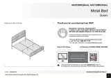
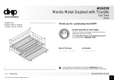
4151639N(Black),4151939N(White)
Metal
Da
y
bed
With
Trund
el
Full
-
Twin

2
Work in a spacious area and near where the unit will be used, preferably on a
carpet, or use a piece of the cardboard packaging to protect your floor and product.
Make sure all parts are included. Most parts are labeled or stamped on the raw
edge.
Read each step carefully. It is very important that each step of the instructions is
performed in the correct order. If these steps are not followed in sequence,
assembly difficulties will occur.
This product may contain small components. Please ensure that they are kept
away from small children.
This product is designed for home use and is not intended for commercial use.
For help with assembly, identifying parts, product information or to order parts,
please contact us:
Limited 1 year Warranty
DHP warrants this product to be free from defects in material and workmanship
and agrees to remedy any such defect. This warranty covers one year from the
date of original purchase from authorized retailers. This is solely limited to the
repair or replacement of defective parts and assembly labor is not included.
This warranty does not apply to any product which has been improperly
assembled, subjected to misuse or abuse or which has been altered or repaired in
any way.The warranty does not cover wearing, tearing, fading or splitting of the
fabric (where applicable). Liability for consequential damages is excluded to the
extent exclusion is permitted by law. This warranty gives you specific legal rights
and you may also have other rights which vary from state to state or province to
province.
To obtain warranty service, purchaser must present original bill of sale.
Components repaired or replaced are warranted through the remainder of the
original warranty period only. The defective components will be repaired or
replaced without charge, subject to the terms and conditions described above.
The terms and conditions of the limited warranty are subject to change without
notice. For the latest warranty policy, please visit www.dhpfurniture.com.
Contact Us!
Read Before Beginning Assembly
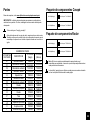
Do NOT use
powertools
This product is shipped in
1 carton
1
.5
hour
s

3
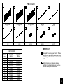
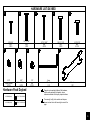
PARTS LIST
Q
W
Y
N
M
O
E
G
P
Y
X
H
J
W
N1
Q
F1
F2

4
IMPORTANT:
Each part has a unique part number. Please
reference the appropriate part number when
contacting customer service for replacement
parts.
Before throwing any packaging, please
verify all contents and make sure you have
received all the parts listed above!
Leg Cap
T393370
X 4
Leg Cap
T393370
X 4
PART
LABELS
4151639N
(Black)
4151939N
(White)
F1
F2
G
J
PT919610 T930230
XT953960 T953940
H T958740 T916440
W T919480 T919480
QT919490 T919490
Y T392590 T392590
Slat
20 PCS
Side Rail
1 PCS
Rear Guard Rail
1 PC
End Guard Rail
1 PC
End Guard Rail
1 PC
Center Brace
1 PC
End Brace
2 PCS
Spacer
40 PCS
Spacer
38 PCS
Plug
40 PCS
G
PARTS LIST
PART NUMBERS
F
1
F
2
JP
XH
W
Q
Y
T1021980
T1021990
T1022000
T1022010
T10220
2
0
T10220
3
0
T10220
4
0
T10220
5
0

5
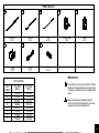
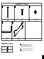
IMPORTANT:
Each part has a unique part number. Please
reference the appropriate part number when
contacting customer service for replacement
parts.
Before throwing any packaging, please
verify all contents and make sure you have
received all the parts listed above!
Leg Cap
T393370
X 4
Leg Cap
T393370
X 4
PART
LABELS
4151639N
(Black)
4151939N
(White)
E T949290 T951650
M T910390 T926110
O T919600 T930130
N1 T949300 T949270
NT949310 T949280
WT919480 T919480
QT919490 T919490
Y T392590 T392590
Caster
2 PCS
Locking Caster
2 PCS
Slats
20 PCS
End Rail
2 PCS
Spacer
20 PCS
Spacer
19 PCS
Plug
40 PCS
PARTS LIST
PART NUMBERS
WQY
E M O N
N1
Side
Rail
2
PCS

6
Please do not completely tighten all the hardware,
until the entire assembly is complete, unless
otherwise indicated in the step-by-step instructions.
The screw(s), bolt(s) to be used at each step are
shown in actual size in the lower right corner of the
page.
4151639N(Black)
4151939N(White)
1234 5
76
4mm
L-Allen Key
1 PC
Wrench
1 PC
1/4" X 3/4"
Bolt
2 PCS
1/4" X 1 9/16"
Bolt
4 PCS
5/16" X 7/8"
Bolt
8 PCS
1/4" X 1 3/4"
Bolt
2 PCS
1/4"
Nut
2 PCS
89 10
5/16"
Spring Washer
8 PCS
5/16"
Curved Washer
8 PCS
1/4" X 1 7/16"
Bolt
2 PCS
Hardware
Pack
Daybed
HARDWARE
LIST
-DAYBED
HP
#
:
T
4151639N-00
HP
#
:
T
4151939N-00

7
Please do not completely tighten all the hardware,
until the entire assembly is complete, unless
otherwise indicated in the step-by-step instructions.
The screw(s), bolt(s) to be used at each step are
shown in actual size in the lower right corner of the
page.
4151639N(Black)
4151939N(White)
Hardware Pac
k Trundle
123
45
4mm
L-
A
lle
n
K
ey
1 PC
Wrench
1
PC
1/4" X 1 5/16"
Bolt
4 PCS
1/4" X 5/8"
Bolt
8 PCS
1/4"
Nut
4 PCS
HP
#
:
T5585196-02
HP
#
:
T5585096-02
HARDWARE
LIST
-TRUNDLE

8
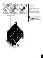
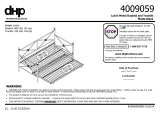
Discard
Step
1
To
Protect
the
Rear
Guard
Rail
G, we've
added
two
extra
Bars.
Please
remove
and
discard
the
Bars
before
starting
the assembly.

BR
9
X 4X 4
F1
F2
J
F2
J
5
6
7
X 4
7
6
5
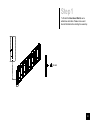
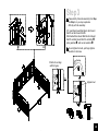
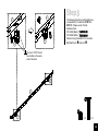
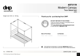
Step
2
Wide side of the slot
should
be facing up !
J
The
following
instructions
will
illustrate
how
to
assemble
the
Daybed
from
Step
2
to
Step
7.
Please
use
the
Daybed Hardware
Pack:
4151639N(Black):
T4151639N-00.
4151939N(White):
T4151939N-00.
Attach
Side
Rail
J
to
End
Guard
Rail
F1
and
End
Guard
Rail
F2
with
bolts
,
s
p
rin
g
washers
,
and
curved
washers
.

BL
BT
10
X 4
X 4 X 4
F1
F2
J
G
J
F2
6
7
5
5
6
7
GF2
F2
G
5
6
7
Pull Up
If Bolts
do
not
align
with
the holes.
Aligned now!
3
2.
3
.
1
G
G
G
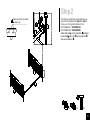
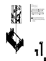
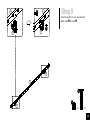
Step
3
Please
strictly
follow
the
assembly
from
Step
3
to
Step
4,
or
you
may experience
difficulty with the assembly.
3.1
Insert
Rear Guard
Rail
G
onto
End Guard
Rail
F1
and
End Guard
Rail
F2.
3.2
Attached
Rear Guard
Rail
G
to
End
Guard
Rail
F1
and
End Guard
Rail
F2
with
bolts
,
spring
washers
,
and
curved
washers
.
Do
not
tighten
the
bolts,
just
finger
tighten
the
bolts
to
the
holes.

BV
Attach sub-assembly side rail E/F from
previous step to post A X 2, headboard C
and footboard D with bolts , spring washers
, metal washers .
Screw bolts , into post A X 2 and footboard
D.
G
F1
F2
F1
G
1
2
X 2
X 2
2
1
1
1
.
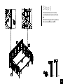
Step
4
Screw Rear Guard Rail
G
to
End Guard Rail
F1
and
End Guard Rail
F2
with bolts
.
Screw
End Guard Rail F1
and
End Guard
Rail
F2
to Rear Guard Rail
G
with bolts
.
Make
sure
all
bolts
before
this
step
are
loose
so
that
you
can
move
parts
to
align
the
holes.
........

BN
X 4
X 2
X 2
J
H
X
H
H
H
J
X
5.1 5.2
3
4
3
8
4
8
1
2
G
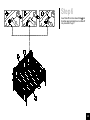
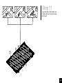
Step
5
5.1
Attach
End
Brace
H
X
2
to
Rear
Guard
Rail
G
and
Side Rail
J
with
bolts
.
5.2
Attach
Center Brace
X
to
End Brace
H
X
2
with
bolts
and
nuts
.

P
Y
PP
J
P
Y
G
GGG
1
3
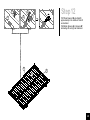
Step
6
Insert
Slat
s
P
into
Rear Guard Rail
G
and
Side Rail
J
as
illustrated,then
lock
Slats
P
into
place
with
Plug
s
Y.

H
G
I
I
H
P
W
Q
P
P
17
.
5
"
17.5"
17.5"
1
4
7
.1
7
.2
W
WQ
Step
7
7
.1
Press
Spacer
s
W
onto
Slats
P
as
illustrated.
7
.2
Attach
Spacer
s
Q
to
Spacers
W
alternating
left
and
right
as
illustrated.
For
better
performance,
attach
the
Slat
Spacers
W
&
Q
at
equal
spaces.
(Approximately
=
17.5
inches
or
445
mm
for
upper
bed).

AL
AM
The Lever "OFF" should
be oriented on the same
side of slat slots.
X 2 X 2
3
1
EE
E
N1
N1
N1
N1
1
3
1
5
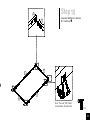
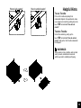
Step
8
The
following
instructions
will
illustrate
how
to
assemble
the
Trundle
from
STEP
8
to
STEP
1
2
.
Please
use
the
Trundle
Hardware
Pack:
4
1516
39
N
(Black)
:
T5585196-02
4
1519
39
N
(White)
:
T5585096-02.
Attach
Locking Caster
N1
X
2
to
one
Side
Rail
E
with
bolts
and
nuts
.

AN
AP
3
1
X 2X 2
E
E
E
N
N
N
N
1
3
1
6
Step
9
Attach
Caster
N
X
2
to
the
other
Side Rail
E
with
bolts
and
nuts
.

BY
X 8
2
E
M
E
E
M
M
Note:
The
l
ever "O
N
" should
be oriented on the
outer
side.
1
7
Step
10
Attach
End Rail
M
X
2
to
Side Rail
E
X
2
with
bolts
.

Y
EEE
OOO
E
E
O
Y
1
8
Step
11
Insert
Slats
O
into
Side Rail
E
X
2
as
illustrated,then
lock
Slats
O
into
place
with
Plugs
Y.

WQ
OO
W
WQ
O
1
9
1
2
.1 1
2
.2
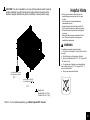
Step
12
1
2
.1
Press
Spacers
W
onto
Slats
O
approximately
in
the
middle
of
Slats
O
as
illustrated.
1
2
.2
Attach
Spacers
Q
to
Spacers
W
alternating
left
and
right
as
illustrated.

How to lock
caster!
Ho
w
to
un
l
ock
ca
s
t
er!
To use
Trundle:
Pull out
the trundle
completely from
underneath daybed.
Once
positioned,
make
sure
casters
are
locked by
pushing
down the
lever
"ON" as
illustrated
"How
to
lock
caster!".
To store Trundle:
Unlock the
casters
by
pulling up
the
lever
"ON" as
illustrated
"How
to
unlock
caster!" and push in the Trundle underneath
the
Daybed.
Helpful Hints
WARNINGS:
Keep
casters
in
lock
condition under
normal
use
to
prevent
unintentional movement
which may
lead
to instability
and tipping.
20
La page est en cours de chargement...
La page est en cours de chargement...
La page est en cours de chargement...
La page est en cours de chargement...
La page est en cours de chargement...
La page est en cours de chargement...
La page est en cours de chargement...
-
 1
1
-
 2
2
-
 3
3
-
 4
4
-
 5
5
-
 6
6
-
 7
7
-
 8
8
-
 9
9
-
 10
10
-
 11
11
-
 12
12
-
 13
13
-
 14
14
-
 15
15
-
 16
16
-
 17
17
-
 18
18
-
 19
19
-
 20
20
-
 21
21
-
 22
22
-
 23
23
-
 24
24
-
 25
25
-
 26
26
-
 27
27


Dorel Home 4151639N Assembly Manual
- Catégorie
- Supports d'équipement audiovisuel
- Taper
- Assembly Manual
dans d''autres langues
- English: Dorel Home 4151639N
- español: Dorel Home 4151639N
Documents connexes
-
Dorel Home 4009029 Manuel utilisateur
-
 Dorel Home 4374439N Assembly Instructions
-
 Dorel Home 4643139MK Assembly Manual
-
 Dorel Home 4706019 Assembly Manual
-
 Dorel Home 4706029 Assembly Manual
-
 Dorel Home 4673639 Assembly Manual
-
 Dorel Home 4704339WE Assembly Manual
-
 Dorel Home 4718349 Assembly Manual
-
 Dorel Home 2553359 Assembly Manual
-
 Dorel Home DA2006379N Assembly Instructions


Autres documents
-
ROOMS TO GO 41432016 Assembly Instructions
-
DHP DE48174 Mode d'emploi
-
 Dorel Home Products 4024259 Le manuel du propriétaire
-
-
-
 Dorel Home Furnishings 4009059 Le manuel du propriétaire
-
-
 Dorel Home Furnishings 4073119 Le manuel du propriétaire
-
 Dorel Home Furnishings 4073719 Le manuel du propriétaire


