HUANUO HNCM1 Guide d'installation
- Catégorie
- Supports de bureau à panneau plat
- Taper
- Guide d'installation
Ce manuel convient également à

Model: HNCM17
Thank you for choosing this HUANUO product! At HUANUO we strive to
provide you with the best quality products and services in the industry.
Should you have any issues, please don't hesitate to contact us at
Technical Support:
(US/CA) 1-800-556-0533 Mon-Fri 8am - 8pm (CST)
(UK) 44-808-196-3874 Mon-Fri 2pm - 10pm (UTC)
Other Info:
[email protected] (US/CA)
[email protected] (DE/UK/FR/IT/ES/NL/SE/AU/PL)
V4.0(A)
Monitor Desk Mount Instruction Manual
English ------------------------------- 01-07
Deutsch ------------------------------- 08-14
Français ------------------------------- 15-21
Español ------------------------------- 22-28
Italiano ------------------------------- 29-35

01 02 03 04 05 06 07
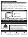
IMPORTANT SAFETY INSTRUCTIONS
• Please carefully read all instructions before attempting installation. If you do not
understand the instructions or have any concerns or questions, please contact our
customer service at [email protected].
CAUTION: Avoid potential personal injuries and property damage!
• Do not use this product for any purpose that is not explicitly specified in this manual.
Do not exceed weight capacity. We are not liable for damage or injury caused by
incorrect assembly or inappropriate use.
• The desk must be capable of supporting five times the weight of the monitor and
mount combined.
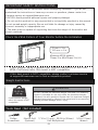
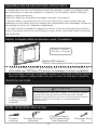
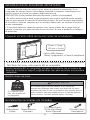
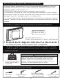
Check the VESA Pattern of Your Monitor before the Installation
If this desk mount is NOT compatible, please contact customer service
at [email protected] to find a compatible product.
If your monitor VESA is greater than 100x100 mm/4x4 in or less than
VESA 75x75mm/3x3in, this mount is NOT compatible.
75 mm ≈ 3 in
100 mm ≈ 4 in
Minimum VESA pattern:
75mm/3 in (W)x75mm/3 in (H)
MAX:100
mm/4 in.
MAX:100
mm/4 in
MAX:100
mm/4 in
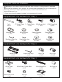
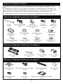
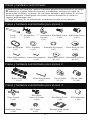
Tools Need(Not Included)
Electric Drill
(Optional) 7/16 in (11mm) - 55/64 in (22mm)
Drill Bit(Optional)
Phillips
Screwdriver
Weight Restrictions
DO NOT exceed the maximum weight indicated.This mounting
system is intended for use only within the maximum weights
indicated. Use with products heavier than the maximum weights
indicated may result in failure of the mount and its accessories,
causing possible damage and or injury.
WARNING
22.05 lbs.
(10 kg)
If your monitor weighs
more, this mount is NOT
compatible.
3/8 in (10mm)
Wrench

01 02 03 04 05 06 07
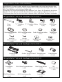
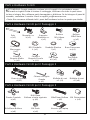
Large Allen Key
o (x1) Wire Clip
n1 (x1) Wire Clip
n2 (x6)
Supplied Parts and Hardware for Step 2
VESA Plate
e (x3) M4x12mm Thumb Bolt
q (x8) M4 Spacer
s (x8)
M4x30mm Bolt
r (x8)
Laptop Tray
t (x1)
M4x10mm Bolt
u (x4) M4 Nut
v (x4)
Supplied Parts and Hardware for Step 3
Warning: This product contains small items that could be a choking hazard if swallowed.
Before starting assembly, verify all parts are included and undamaged. Do not use damaged or
defective parts. lf you require replacement parts, contact customer service at
• Please note: Not all hardware included in this package will be used.
Supplied Parts and Hardware
Pole
a (x1) C Clamp Plate
b (x1) C Clamp Plate
c (x1) M5x16mm Bolt
f (x3) M8x12mm Bolt
g (x2)
Medium Allen Key
o (x1) Small Allen Key
o (x1) Bottom Pad
w2 (x1)
Grommet Plate
m (x1)
Locking Plate
j (x1) Spring Washer
l (x1)
M10 Washer
k (x1)
Supplied Parts and Hardware for Step 1
Bottom Pad
w1 (x1)
Swivel Arm
d (x1)

01 02 03 04 05 06 07
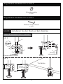
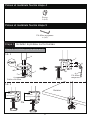
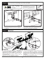
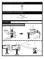
Step 1 Install the Pole to the Desktop
Option A: Desk Clamp Assembly
1A-1
1A-2
Nut
h (x3)
Supplied Hardware for Step 4
Supplied Hardware for Step 5
Medium Allen Key
o (x1)
c
b
g
o
Medium
Allen Key
OR b
a
c
f
w1
o
Small Allen Key
70mm
2 3/4 in 100mm
3 15/16 in
Desk

01 02 03 04 05 06 07
j
k
l
Phillips Screwdriver
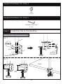
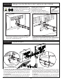
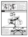
Step 2 Install Swivel Arms to the Pole
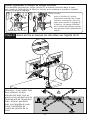
Option B: Grommet Base Assembly
1. If the existing grommet hole comes with a plastic protector, remove it to ensure
a flat surface before installing the desk mount.
2. If there is no grommet hole on your desk, mark the pilot hole on your your
desired position. Drill a hole using the drill bit in a diameter of 7/16 in (11mm) -
55/64 in (22mm) at the marked position through the mounting surface.
Note:
a
f
m
w2
o
Small Allen Key
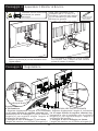
Install swivel arms (d) to the pole (a). Fasten the bolt with supplied Allen key (o).
Attach the wire clip (n1,n2) to the pole (a) and swivel arms (d).
d
o
n1
n2
d
UP
Phillips Screwdriver
(Not lncluded)
Applicable Desk
Thickness:70mm
a

01 02 03 04 05 06 07
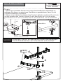
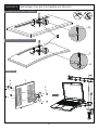
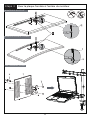
Step 3 Attach the VESA Plate to the Laptop Tray or Monitor
For Laptop
For Monitor with Flat Back
For Monitor with Curved
or Recessed Back
q
r
s
e
t
u
v

01 02 03 04 05 06 07
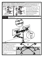
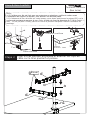
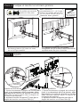
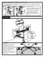
Step 4 Secure the Monitor or Laptop Tray onto the Head of Swivel
Arm
h
4-1 Slide the monitor onto the head of
Swivel Arm (d) as shown in the above
diagram.
4-2 Secure the Nut (h). Make sure the nut
is installed before you rotate the monitor.
HEAVY! You may need
assistance with this step.
Step 5 Adjustment
1. Directly swivel your monitor to your desired
angle(if it is difficult to swivel the monitor, for
better to tilt Monitor you can slightly loosen
the nuts using the Allen key).
2. Tighten the nuts to hold the monitor in
place.
Swivel Adjustment
T
o
Medium
Allen Key
Tilt Adjustment
1. Directly tilt your Monitor to your desired
angle(if it is difficult to tilt the Monitor, for
better to tilt monitor you can slightly loosen
the nuts [T] using the Allen key).
2. Tighten the nuts [T] to hold the monitor in
place.
o
Medium
Allen Key
Note: Please refer the proce-
dures 4-1 and 4-2 to install
the laptop tray [t] with VESA
plate [e] onto the head of
swivel arm Wrench
3/8 in. (10mm)
(Not Included)
d

01 02 03 04 05 06 07
Step 6 Manage the Wires and Store the Allen Keys on Wire Clip
If the monitor is lower, remove the nut [h] and turn the bolt counter-clockwise with
supplied Allen key [o] to raise the monitor. Install the nut [h] after the adjustment.
Slightly Adjust the Height of each Monitor
h
Use the Allen key [o] to slightly
adjust the height of each monitor
and re-tighten the nut [h] after
finishing height adjustment.
Individual monitor height adjust-
ment helps monitors to be
perfectly aligned.
②
①o
Small Allen Key
Remove the nut [h]
Warning:
To avoid tipping, please be
careful not to extend the arms
too far forward or backward.
When you adjust the angle of
the arms, please make sure
two arms are balanced to
avoid instability of the center
of gravity of the base.

08 09 10 11 12 13 14
WICHTIGE SICHERHEITSHINWEISE
• Bitte lesen Sie alle Anweisungen sorgfältig durch, bevor Sie installieren. Wenn Sie
dieses Handbuch nicht verstehen oder Fragen haben, wenden Sie sich bitte an unseren
Kundenservice unter [email protected].
Attention: évitez les potentiels dommages corporels et aux biens
• Ne pas utilizer ce produit dans le cas où cet instruction n’a pas indiqué. Ne pas
dépasser le poids limité. Nous ne sommes pas responsables des dommages causés par
le montage incorrect ou l’utilisation inappropriée.
• La table doit être capable de supporter au moins 5 fois du poids total (les poids du
socle, le moniteur et tous les accessoires), ne pas utiliser ce pruoduit dans un panneau
des particules.
Überprüfen Sie vor der Installation das VESA Muster des Monitore
Falls diese Halterung NICHT kompatibel ist, wenden Sie sich an den
Kundendienst unter [email protected], um eine kompatible
Installation zu finden.
Falls Ihr Monitore-VESA größer als 100 x 100 mm/4 x 4 zoll. oder weniger
als 75x75mm/3 x 3 zoll ist, ist diese Installation NICHT kompatibel.
75 mm ≈ 3 Zoll
100 mm ≈ 4 Zoll
Minimales VESA Muster:
75mm/3 Zoll(Breite) x 75mm/3 Zoll(Höhe)
MAX:100
mm/4 in.
MAX:100
mm/4 Zoll
MAX:100
mm/4 Zoll
Werkzeuge benötigt (nicht enthalten)
Elektrische
Bohrmaschine(Optional)
11 mm (7/16 Zoll) oder
22 mm (55/64 Zoll)
Bohrer(Optional)
Kreuzschraubendrehe
Gewichtsbeschränkungen
Überschreiten Sie NICHT das angegebene Maximalge
wicht. Das Montagesystem kann nur innerhalb des
angegebenen Maximal-gewichts verwendet werden. Die
Verwendung von Produkten, die schwerer als das ngegebene
Maximalgewicht sind, kann zum Ausfall der Halterung
und des Zubehörs führen und zu Verletzungen führen.
WARNUNG
22.05 lbs.
(10 kg)
Wenn Ihr Fernseher
schwerer ist, ist diese
Halterung nicht kompatibel.
3/8 Zoll(10mm)
Schraubenschlüssel

08 09 10 11 12 13 14
Großer Inbusschlüssel
o (x1) Kabelklemme
n1 (x1) Kabelklemme
n2 (x6)
Mitgelieferte Teile und Hardware für Schritt 2
Frontplatte
e (x3) M4x12mm Daumenbolzen
q (x8) M4
Abstandshalter
s (x8)
M4x30mm Bolzen
r (x8)
Laptopfach
t (x1)
M4x10mm Bolzen
u (x4) M4 Schraubenmutter
v (x4)
Mitgelieferte Teile und Hardware für Schritt 3
WARNUNG: Dieses Produkt enthält kleine Gegenstände, die beim Verschlucken eine
Erstickungsgefahr verursachen können.Stellen Sie vor Beginn der Montage sicher, dass
alle Teile enthalten und nicht beschädigt sind.
Verwenden Sie keine beschädigten oder defekten Teile. Wenn Sie Ersatzteile benötigen,
wenden Sie sich bitte an unseren Kundenservice unter [email protected].
• Bitte beachten Sie: Es wird nicht alle in diesem Paket enthaltene Hardware verwendet.
Mitgelieferte Teile und Hardware
Mast
a (x1) “C” Klemmer
b (x1) “C” Klemmer Stütze
c (x1)
Bolzen
M5x16mm
f (x3)
Bolzen
M8x12mm
g (x2)
Mittlerer
Inbusschlüssel
o (x1)
Kleiner
Inbusschlüssel
o (x1) Unteres Pad
w2 (x1)
Tüllenplatte
m (x1)
Verriegelungsplatte
j (x1) Feder Unterlegscheibe
l (x1)
M10 Unterlegscheibe
k (x1)
Mitgelieferte Teile und Hardware für Schritt 1
Unteres Pad
w1 (x1)
Schwenkarm
d (x1)

08 09 10 11 12 13 14
Schritt 1 Installieren Sie den Mast auf dem Desktop
Option A: Installation der C-Klemme
1A-1
1A-2
Schraubenmutter
h (x3)
Mitgelieferte Hardware für Schritt 4
Mitgelieferte Hardware für Schritt 5
Mittlerer Inbusschlüssel
o (x1)
c
b
g
o
Mittlerer
Inbusschlüssel
Oder b
a
c
f
w1
o
Kleiner Inbusschlüssel
70mm
2 3/4 Zoll 100mm
3 15/16 Zoll
Tischdicke

08 09 10 11 12 13 14
j
k
l
Kreuzschraubendrehe
Schritt 2
Option B: Tülleninstallation
Hinweis:
1. Wenn das vorhandene Ösenloch mit einem Kunststoffschutz ausgestattet ist,
entfernen Sie diesen, um eine ebene Oberfläche zu gewährleisten, bevor Sie die
Schreibtischhalterung installieren.
2. Wenn sich auf Ihrem Schreibtisch kein Ösenloch befindet, markieren Sie ein Loch
an Ihrer gewünschten Position. Bohren Sie mit dem Bohrer ein Loch mit einem
Durchmesser von 11 mm (7/16 Zoll) oder 22 mm (55/64 Zoll) ) an der markierten.
a
f
m
w2
o
Kleiner Inbusschlüssel
d
o
n1
n2
d
OBEN
Kreuzschraubendrehe
(Nicht enthalten)
Tischdicke:70mm
a
Befestigen Sie den Schwenkarm am Mast und befestigen
Sie die Kabelklemmen am Schwenkarm und am Mast

08 09 10 11 12 13 14
Schritt 3 Befestigen Sie die Frontplatte am Monitor
Laptopfach
FLACHER BILDSCHIRM MONITOR
CURVED BILDSCHIRM MONITOR
q
r
s
e
t
u
v

08 09 10 11 12 13 14
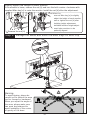
Schritt 4 Hängen Sie die Monitore oder Laptop an den Stände
h
4-1 Schieben Sie den Monitor wie in
der obigen Abbildung gezeigt auf den
Kopf des Schwenkarms [d].
4-2 Ziehen Sie die Schraubenmutter [h] mit
einem 3/8 Zoll Schraubenschlüssel (10mm)(Nicht
enthalten) an. Stellen Sie sicher, dass die Mutter fest
angezogen ist, bevor Sie den Monitor drehen.
SCHWER! Möglicherweise
benötigen Sie Unterstützung
bei diesem Schritt.
Schritt 5 Anpassungen
1. Stellen Sie den Flip-Einstellung direkt ein (wenn
die Einstellung jedoch zu schwierig ist, lösen Sie die
Stellschraube mit dem Inbusschlüssel [o] leicht, um
den Flip-Einstellung des Monitors besser einstellen
zu können.)
2. Ziehen Sie die Stellschraube an, um den Winkel
des Monitors mit dem Inbusschlüssel [o] zu fixieren.
Flip-Einstellung
T
o
Mittlerer
Inbusschlüssel
Neignungseinstellung
1. Stellen Sie den Neigungswinkel direkt ein (wenn
die Einstellung jedoch zu schwierig ist, lösen Sie die
Stellschraube [T] mit dem Inbusschlüssel [o] leicht,
um den Neigungswinkel des Monitors besser einstel-
len zu können.)
2. Ziehen Sie die Stellschraube [T] an, um den Winkel
des Monitors mit dem Inbusschlüssel [o] zu fixieren.
o
Mittlerer
Inbusschlüssel
Schraubenschlüssel
3/8 Zoll(10mm)
(Nicht enthalten)
d
Hinweis: Bitte beachten Sie
dieVerfahren 4-1 und 4-2
bisInstallieren Sie das
Laptopfach [t] mitFrontplatte
[e] auf den Kopfdes Schwenkarms

08 09 10 11 12 13 14
Schritt 6 Verwalten Sie das Kabel und halten Sie die Inbusschlüssel auf dem
Drahtklemme
Wenn der Monitor niedriger ist, entfernen Sie die Schraubenmutter [h] und drehen Sie die
Schraube mit dem mitgelieferten Inbusschlüssel [o] gegen den Uhrzeigersinn, um den
Monitor anzuheben. Installieren Sie die Schraubenmutter [h] nach der Einstellung.
Passen Sie die Höhe jedes Monitors leicht an
h
Verwenden Sie die Inbus-Taste
[o], um die Höhe jedes Monitors
leicht einzustellen, und ziehen Sie
die Schraubenmutter [h] nach
Abschluss der Höheneinstellung
wieder fest. Durch die individuelle
Einstellung der Monitorhöhe
können die Monitore perfekt
ausgerichtet werden.
②
①o
Kleiner Inbusschlüssel
Entfernen Sie die
Mutter [h]
Warnung:
Um ein Umkippen zu vermeiden,
achten Sie bitte darauf, die
Arme nicht zu weit nach vorne
oder hinten zu strecken.Wenn
Sie den Winkel der Arme
einstellen, stellen Sie bitte
sicher, dass zwei Arme ausgeg-
lichen sind, um eine Instabilität
des
Schwerpunkts der Basis zu
vermeiden.

15 16 17 18 19 20 21
INFORMATION DE SÉCURITAIRE IMPORTANTE
• Veuillez bien lire tous les instructiona avant du montage. Si vous ne comprenez pas
les instructions ou avez des questions, contactez s’il vous plaît le service client par
Attention: évitez les potentiels dommages corporels et aux biens!
• Ne pas utilizer ce produit dans le cas où cet instruction n’a pas indiqué. Ne pas
dépasser le poids limité. Nous ne sommes pas responsables des dommages causés par
le montage incorrect ou l’utilisation inappropriée
• La table doit être capable de supporter au moins 5 fois du poids total (les poids du
socle, le moniteur et tous les accessoires), ne pas utiliser ce pruoduit dans un panneau
des particules.
Vérifier le Modèle VESA du Moniteur avant l’Installation
Si ce montage n’est pas compatible, veuillez s’il vous plaît contacter service
client par [email protected] pour trouver un montage compatible
Si votre moniteur VESA est plus grande que 100*100mm/4*4 pouce, ou
plus petite que 75*75mm/3*3 pouce. Ce montage n’est pas compatible.
75 mm ≈ 3 pouce
100 mm ≈ 4 pouce
Modèle VESA minimal :
75mm/3 pouce(largeur)x75mm/3 pouce(hauteur)
MAX:100
mm/4 in.
Maximum:
100 mm/4 pouceb
Maximum:
100 mm/4 pouceb
Outils nécessaires (Non Inclus)
Perceuse électrique
(Optionnel)
7/16 pouce(11mm) -
55/64 pouce(22mm)
Foret (Optionnel)
Tournevis
cruciform
Restriction de Poids
Ne pas dépasser le poids max. indiqué, car le présent système
ne peut être utilisé que dans les limites de poids indiqués.
Utilisation de produit plus lourd que le poids maximum spécifié
menerait à l’échec de montage, et l’endommagement
d’accessoiress.
ATTENTION
22.05 lbs.
(10 kg)
Si votre TV pèse plus,
ce montage n’est pas
compatible
3/8 pouce(10mm)
Clé

15 16 17 18 19 20 21
Grande clé Allen
o (x1) Pince à câble
n1 (x1) Pince à câble
n2 (x6)
Pièces et matériels fournis pour la étape 2
Plaque frontale
e (x3) M4x12mm Boulon à ailettes
q (x8) M4 Rondelle
s (x8)
M4x30mm Boulon
r (x8)
Plateau pour ordinateur portable
t (x1)
M4x10mm Boulon
u (x4) M4 Écrou
v (x4)
Pièces et matériels fournis pour la étape 3
Attention: Ce produit contient des petits articles qui risquent d’étoffer en cas
d’avalement Verifier tous les pièces sont compris et intacts avant le montage.Ne
pas utiliser les pièces endommagés ou défectueuses. Si vous avez besoin de pièce
de rechange,contactez notre service client par [email protected].
• Bitte beachten Sie: Es wird nicht die gesamte mitgelieferte Hardware erwendet.
Pièces et matériels fournis
Poteau
a (x1) Pièce de serrage
b (x1) Pièce de
serrage de renfort
c (x1)
Boulon
M5x16mm
f (x3)
Boulon
M8x12mm
g (x2)
Clé Allen moyenne
o (x1) Petite clé Allen
o (x1) Patin de fond
w2 (x1)
Plaquette de
passe-fils
m (x1)
Plaque de
verrouillage
j (x1)
Rondelle ressort
l (x1)
M10 Rondelle
k (x1)
Pièces et matériels fournis pour la étape 1
Patin de fond
w1 (x1)
Bras articulés
d (x1)

15 16 17 18 19 20 21
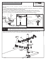
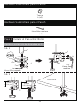
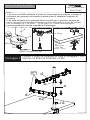
Étape 1 Installer le poteau sur le bureau
Choix A: Installation par la pince en C
1A-1
1A-2
Écrou
h (x3)
Pièces et matériels fournis étape 4
Pièces et matériels fournis étape 5
Clé Allen moyenne
o (x1)
c
b
g
o
Clé Allen
moyenne
Ou b
a
c
f
w1
o
Petite clé Allen
70mm
2 3/4 pouce 100mm
3 15/16 pouce
Bureau

15 16 17 18 19 20 21
j
k
l
j
k
l
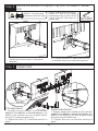
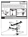
Étape 2
Choix B: Base à œillets
Notes
1. Si l’orifice pour fils est livré avec un protecteur en plastique, veuillez le retirer avant
l’installation du support du bureau, pour assurer une surface plane.
2. En l'absence de trou d'oeillet sur votre bureau, vous devez positionner le poteau [01] sur la
surface de montage et marquer le trou. Puis, à l'aide du foret de diamètre de 7/16 po (soit 11
mm) - 55/64 po (soit 22 mm), percez un trou à la position marquée à travers la surface de
montage.
a
f
m
w2
o
Petite clé Allen
Fixer le bras pivotant au poteau et attacher les clips de
câble sur le bras pivotant et poteau
d
o
n1
n2
d
Élever
Tournevis cruciform
(Non Inclus)
Épaisseur
du bureau:70mm
Tournevis cruciform
a

15 16 17 18 19 20 21
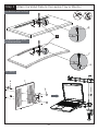
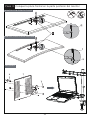
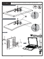
Étape 3 Fixer la plaque frontale à l'arrière du moniteur
Pour l'ordinateur portable
MONITEUR À DOS PLAT
MONITEUR ARRIÈRE COURBÉ
q
r
s
e
t
u
v
La page est en cours de chargement...
La page est en cours de chargement...
La page est en cours de chargement...
La page est en cours de chargement...
La page est en cours de chargement...
La page est en cours de chargement...
La page est en cours de chargement...
La page est en cours de chargement...
La page est en cours de chargement...
La page est en cours de chargement...
La page est en cours de chargement...
La page est en cours de chargement...
La page est en cours de chargement...
La page est en cours de chargement...
La page est en cours de chargement...
La page est en cours de chargement...
-
 1
1
-
 2
2
-
 3
3
-
 4
4
-
 5
5
-
 6
6
-
 7
7
-
 8
8
-
 9
9
-
 10
10
-
 11
11
-
 12
12
-
 13
13
-
 14
14
-
 15
15
-
 16
16
-
 17
17
-
 18
18
-
 19
19
-
 20
20
-
 21
21
-
 22
22
-
 23
23
-
 24
24
-
 25
25
-
 26
26
-
 27
27
-
 28
28
-
 29
29
-
 30
30
-
 31
31
-
 32
32
-
 33
33
-
 34
34
-
 35
35
-
 36
36


HUANUO HNCM1 Guide d'installation
- Catégorie
- Supports de bureau à panneau plat
- Taper
- Guide d'installation
- Ce manuel convient également à
dans d''autres langues
- italiano: HUANUO HNCM1 Guida d'installazione
- español: HUANUO HNCM1 Guía de instalación
- Deutsch: HUANUO HNCM1 Installationsanleitung