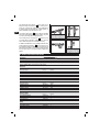
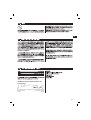
Hilti DX 351 BT Manuel utilisateur
- Catégorie
- Cloueuse
- Taper
- Manuel utilisateur

enOperating instructions
Mode d’emploi fr
zh
ja
ko
ar
DX 351 BT/BTG

1
321
DX 351
2
씌
씋씊씈 씉
씍씎 씏
쐃 쐇 쐋 쐏 쐄 쐂 쐆
쐊 쐎 쐅
쐉
쐈
DX 351 BTG
DX 351 BT

3
NO
debris
NO
water
oil etc.
5
Trec
7
> 6
[0.236"]
> 6
[0.236"]
> 15
[0.591"]
> 15
[0.591"]
≥ 8 mm [5/16″]
9
L
HG
8mm
[5/16"]
11
13 14 15
TX-BT 4/7
7.2 mm
Sichtbarer Ring
Visible ring
Cercle visible
Aro visible
4
6
≥ 12 mm
[0.472"]
≥ 6 mm
[0.236"]
8
10
12

16
360
18
21
23
24 25
17
19
20
22

26
28
30
31
33
34
27
29
32


1
en
ORIGINAL OPERATING INSTRUCTIONS
DX351 BT/BTG powder-actuated tool
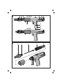
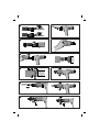
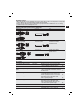
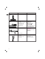
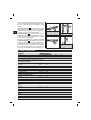
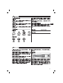
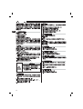
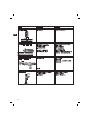
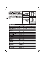
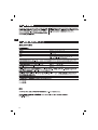
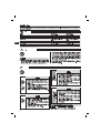
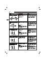
Description of main parts
쐃Fastener guide
쐇Threaded sleeve
쐋Piston return spring
쐏Cartridge strip ejector
쐄Ventilation slots
쐂Power regulation indicator
쐆Power regulation wheel
쐊Housing, black
쐎Trigger
쐅Grip
쐈Cartridge guideway
쐉Grip pad
Tool components
씈Fastener guide*
씉Piston brake
씊Piston*
씋Piston return spring
씌Piston guide
씍Casing, black
씎Piston stop, right
씏Piston stop, left
* These parts may be replaced by the user.
Contents Page
1. Safety precautions 1
2. General information 3
3. Technical description 3
4. Insert tools and accessories 4
5. Technical data 6
6. Before use 6
7. Operation 6
8. Care and maintenance 8
9. Troubleshooting 10
10. Disposal 13
11. Manufacturer's warranty – DX tools 13
12. EC declaration of conformity (original) 13
13. CIP approval mark 14
14. Health and safety of the user 14
It is essential that the operating instructions
are read before the tool is operated for the
first time.
Always keep these operating instructions
together with the tool.
Ensure that the operating instructions are
with the tool when it is given to other per-
sons.
1.1 Basic safety instructions
In addition to the safety precautions listed in the indi-
vidual sections of these operating instructions, the
following points must be strictly observed at all times.
1.2 Only use Hilti cartridges or cartridges of
equivalent quality
The use of cartridges of inferior quality in Hilti tools may
lead to build-up of unburned powder, which may explo-
de and cause severe injuries to operators and bystan-
ders. At a minimum, cartridges must either:
a) Be confirmed by their supplier to have been suc-
cessfully tested in accordance with EU standard EN
16264
NOTE:
●All Hilti cartridges for powder-actuated tools have
been tested successfully in accordance with EN 16264.
●The tests defined in the EN 16264 standard are system
tests carried out by the certification authority using
specific combinations of cartridges and tools.
The tool designation, the name of the certification aut-
hority and the system test number are printed on the
cartridge packaging.
or
b) Carry the CE conformity mark (mandatory in the EU
as of July 2013).
See packaging sample at:
www.hilti.com/dx-cartridges
1.3 Use as intended
The DX351BT and DX351BTG are designed for pro-
fessional use in fastening applications in construction
where X-BT threaded studs are driven into steel.
1.4 Improper use
●Operate the tool only in well-ventilated working areas.
●Manipulation or modification of the tool is not per-
missible.
●Do not operate the tool in an explosive or flamma-
ble atmosphere, unless the tool is specially approved
for such use.
●Use only original Hilti fasteners, cartridges, acces-
sories and spare parts or those of equivalent quality.
●Observe the information printed in the operating
instructions concerning operation, care and mainte-
nance.
1. Safety precautions

2
en
●Never point the tool at yourself or any bystander.
●Never press the muzzle of the tool against your hand
or other part of your body.
●Do not drive nails into excessively hard or brittle
materials such as glass, marble, plastic, bronze, brass,
copper, natural rock, insulation material, hollow brick,
glazed tile, thin-gauge sheet metal (< 4 mm), grey cast
iron, spheroidal cast iron and gas concrete.
1.5 Technology
●This tool is designed with the latest available tech-
nology.
●The tool and its ancillary equipment may present
hazards when used incorrectly by untrained person-
nel or not as directed.
1.6 Making the workplace safe
●Ensure that the workplace is well lit.
●Objects which could cause injury should be removed
from the working area.
●Operate the tool only in well-ventilated working areas.
●The tool is for hand-held use only.
●Avoid unfavorable body positions. Work from a
secure stance and stay in balance at all times
●Keep other persons, children in particular, outside
the working area.
●Before using the tool, make sure that no one
is standing behind or below the point where fasteners
are to be driven.
●Keep the grip dry, clean and free from oil and grease.
1.7 General safety precautions
●Operate the tool only as directed and only when it
is in faultless condition.
●If a cartridge misfires or fails to ignite, proceed as
follows:
1. Keep the tool pressed against the working surface
for 30 seconds.
2. If the cartridge still fails to fire, withdraw the tool
from the working surface, taking care that it is not
pointed towards your body or bystanders.
3. Manually advance the cartridge strip one cartridge.
Use up the remaining cartridges on the strip. Remove
the used cartridge strip and dispose of it in such a
way that it can be neither reused nor misused.
●Never attempt to pry a cartridge from the magazine
strip or the tool.
●Keep the arms flexed when the tool is fired (do not
straighten the arms).
●Never leave the loaded tool unattended.
●Always unload the tool before beginning cleaning,
servicing or changing parts and before storage.
●Unused cartridges and tools not presently in use
must be stored in a place where they are not exposed
to humidity or excessive heat. The tool should be trans-
ported and stored in a toolbox that can be locked or
secured to prevent use by unauthorized persons.
1.8 Temperature
●Do not disassemble the tool while it is hot.
●Never exceed the recommended maximum fasten-
er driving rate (number of fastenings per hour). The
tool may otherwise overheat.
●Should the plastic cartridge strip begin to melt, stop
using the tool immediately and allow it to cool down.
1.9 Requirements to be met by users
●The tool is intended for professional use.
●The tool may be operated, serviced and repaired
only by authorised, trained personnel. This personnel
must be informed of any special hazards that may be
encountered.
●Proceed carefully and do not use the tool if your full
attention is not on the job.
●Stop working with the tool if you feel any pain or
discomfort.
1.10 Personal protective equipment
●The operator and other persons in the immediate
vicinity must always wear approved eye protection, a
hard hat and suitable ear protection.

3
en
3. Technical description
The Hilti DX351BT and DX351BTG are powder-actuat-
ed fastening tools for driving X-BT threaded studs into
steel.
The tool works on the well-proven piston principle and
is therefore not related to high-velocity tools. The pis-
ton principle provides an optimum of working and fas-
tening safety. The tool works with cartridges of 6.8/11
caliber.
Piston return and cartridge transport is fully automatic.
This permits fastenings to be made very quickly and
economically with nails and threaded studs.
As with all powder-actuated tools, the tool, magazine,
fastener program and cartridge program form a “tech-
nical unit”. This means that optimal fastening with this
system can only be achieved if the fasteners and car-
tridges are specially manufactured for it, or products of
equivalent quality, are used. The fastening and applica-
tion recommendations given by Hilti are only applicable
if these conditions are observed.
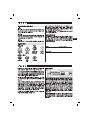
The tool features 5-way safety – for the safety of the
operator and bystanders.
The piston principle
The energy from the propellant charge is transferred to
a piston, the accelerated mass of which drives the fastener
into the base material. As approximately 95 % of the
kinetic energy is absorbed by the piston, the fastener is
driven into the base material at much reduced velocity
(less than 100 m/sec.) in a controlled manner. The dri-
ving process ends when the piston reaches the end of
its travel. This makes dangerous through-shots virtual-
ly impossible when the tool is used correctly.
1
2.1 Signal words
-WARNING-
The word WARNING is used to draw attention to a poten-
tially dangerous situation which could lead to severe
personal injury or death.
-CAUTION-
The word CAUTION is used to draw attention to a poten-
tially dangerous situation which could lead to minor per-
sonal injury or damage to the equipment or other prop-
erty.
-NOTE-
Used to draw attention to an instruction or other useful
information.
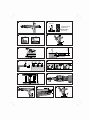
2.2 Pictograms
The numbers refer to the illustrations. The illustra-
tions can be found on the fold-out cover pages. Keep
these pages open while you read the operating instruc-
tions.
In these operating instructions, the designation “the
tool” always refers to the DX351BT/BTG powder-actu-
ated tool.
Location of identification data on the tool
The type designation and the serial number are printed
on the type plate on the tool. Make a note of this infor-
mation in your operating instructions and always refer
to it when making an enquiry to your Hilti representa-
tive or service department.
Type: DX351BT/BTG
Serial no.:
Warning signs
General
warning Warning:
hot surface Read the opera-
tion instructions
before use
Return waste
material for
recycling
Obligation signs
Wear eye
protection Wear a
safety helmet Wear ear
protection
Symbols
2. General information

4
en
The drop-firing safety device is the result of cou-
pling the firing mechanism with the cocking move-
ment. This is designed to help prevent the Hilti DX tool
from firing when it is dropped onto a hard surface, no
matter at which angle the impact occurs.
The trigger safety device ensures that the cartridge
cannot be fired simply by pulling the trigger only. The
tool can be fired only when fully depressed.
The contact pressure safety device requires the tool
to be fully depressed with a significant force. The tool
can be fired only when pressed fully in this way.
In addition, all Hilti DX tools are equipped with an unin-
tentional firing safety device . This prevents the tool
from firing if the trigger is pulled and the tool then pressed
against the work surface. The tool can be fired only when
it is first pressed 쩸correctly and 쩹the trigger then
pulled.
2
3
4
5
1
2
4
2
5
3
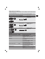
Cartridges
Ordering designation Item no. Quantity Color Power
6.8/11 M brown, “High-precision“ 377204/3 100 Brown Extra light
These cartridges have been designed specially for the X-BT system. Their special power level ensures that driving
power remains within a very narrow scatter band.
4. Insert tools and accessories
Fasteners
Stainless steel threaded studs
Ordering designation Item no. Quantity
X-BT W10-24-6 SN12-R 377076/5 100
X-BT M10-24-6 SN12-R 377078/1 100
X-BT M8-15-6 SN12-R 377074/0 100
X-BT W10-26-6-R 377075/7 100
X-BT M10-24-6-R 377077/3 100
X-BT M8-15-6-R 377073/2 100
Grating flanges
Ordering designation Item no. Quantity
X-FCM-R 25/30 247181/1 100
X-FCM-R 11/4-1/2247173/8 100
X-FCM-R 35/40 247171/2 100
X-FCM-R 45/50 247172/0 100
Fastener guide
Ordering designation Item no. Quantity
X-351-BT FG W1024 378673/8 1
X-351-BT FG M1024 378674/6 1
X-351-BT FG G 378675/3 1
Piston
Ordering designation Item no. Quantity
X-351-BT P 1024 378676/1 1
X-351-BT P G 378677/9 1

5
en
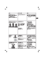
X-351-BT FG M1024 X-351-BT P 1024 X-BT M10-24-6 SN12-R
X-BT M10-24-6-R
X-351-BT FG G X-351-BT P G X-BT M8-15-6 SN12-R
X-BT M8-15-6-R
Accessories
Ordering designation Item no. Application Qty.
X-351-BT CP coating protector 331343/9 Attachment for the fastener guide designed
to prevent damage to painted surfaces. 10
X-BT PRG 8/15 power regulation 377088/0 For checking that fasteners (studs) are driven
guide to the correct depth for X-BT M8 studs. 1
X-BT PRG 10/24 power regulation 377089/8 For checking that fasteners (studs) are driven
guide to the correct depth for X-BT M10, X-BT W10
threaded studs. 1
TX-BT 4/7-80 stepped drill bit 377079/9 For drilling holes for the X-BT M10, X-BT W10
or X-BT M8 threaded studs. Ideal for use in
narrow openings where access is restricted. 10
TX-BT 4/7-110 stepped drill bit 377080/7 For drilling holes for the X-BT M10,
X-BT W10 or X-BT M8 threaded studs.
Ideal for grating fastenings. 10
TX-BT 4/7-150 stepped drill bit 377081/5 For drilling holes for the X-BT M10,
X-BT W10 or X-BT M8 threaded studs.
Ideal for grating fastenings where the parts
to be fastened are of greater height. 10
XBT4000-A drill For drilling holes with the TX-BT4/7-...
stepped drill bits
X-BT CD 18/24 centering device 378885/8 Positioning aid for drilling holes,
particularly where access is restricted. 1
Zuitable fastener guide / piston / fastener / combinations
Fastener guide Piston type Fastener
X-351-BT FG W1024 X-351-BT P 1024 X-BT W10-24-6 SN12-R
X-BT W10-24-6-R
Prevention of misuse:
– When the piston tip is worn or damaged, never try to grind the tip in order to re-use the piston. This may cause
serious damage to the tool and will adversely affect fastening quality.
– Please refer to the table below for the right fastener guide/piston/fastener combination. Use of the wrong
combination may result in damage to the tool.

6
en
-WARNING-
●The base material may splinter when a
fastener is driven or fragments of the
cartridge strip may fly off.
●Flying fragments may injure parts of the
body or the eyes.
●Wear safety glasses and a hard hat (users
and bystanders).
-CAUTION-
●The nail or stud is driven by a cartridge
being fired.
●Excessive noise may damage the hear-
ing.
●Wear ear protection (users and
bystanders).
-WARNING-
●Under certain circumstances, the tool
can be made ready to fire by pressing it
against a part of the body (e. g. a hand).
●When in the “ready to fire” state, a fas-
tener or piston could be driven into a part
of the body.
●Never press the nosepiece of the tool
against parts of the body.
7. Operation
6. Before use
6.1 Tool inspection
●Ensure that there is no cartridge strip in the tool. If
there is a cartridge strip in the tool, remove it by hand
from the tool.
●Check all external parts of the tool for damage at reg-
ular intervals and check that all controls operate prop-
erly. Do not operate the tool when parts are damaged
or when the controls do not operate properly. If nec-
essary, have the tool repaired at a Hilti service centre.
●Check the piston for wear (see “8.4 Care and mainte-
nance”).
-WARNING-
●Under certain circumstances, the tool
can be made ready to fire by pulling back
the fastener guide by hand.
●When in the “ready to fire” state, a fas-
tener or piston could be driven into a part
of the body.
●Never pull back the fastener guide by
hand.
5. Technical data
Tool DX 351 BT DX 351 BTG
Weight 2.28 kg (5 Ibs) 2.36 kg (5.2 Ibs)
Length of tool 403 mm (15.9″) 431 mm (16.9″)
Cartridges 6.8/11 M (27 cal. short) 6.8/11 M (27 cal. short)
brown brown
Recommended max. fastener driving frequency: 700/h 700/h
Cocking movement 59 mm (2.3″) 59 mm (2.3″)
Cocking pressure 100 N 100 N
Right of technical modification reserved
Cleaning set
Hilti spray, flat brush, round brush 19/31 mm, round brush 4.5 mm, round brush 9 mm, cleaning cloth, scraper

7
en
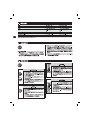
7.1 Fastening guidelines
-NOTE-
These application recommendations must always be
observed. For more specific information, refer to the
Hilti Fastening Technology Manual, which is available
from your local Hilti organisation.
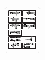
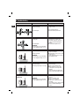
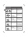
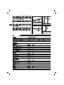
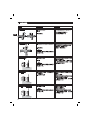
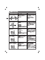
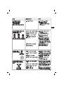
7.1.1 Driving threaded studs
1. Mark the point where the stud is to be driven.
2. Drill a hole. Continue drilling until the drill bit cuts a
bright ring around the hole.
3. Keep the hole clean (clean away any debris, dirt, water
or other liquids).
4. Position the threaded stud in the drilled hole and then
press the tool against the working surface at right
angles.
5. Pull the trigger.
-NOTE-
Never regrind a stepped drill bit. System functionality
can otherwise no longer be acheived.
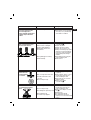
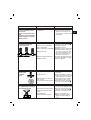
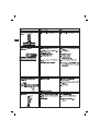
7.2 Technical guidelines
7.2.1 Recommended torque
Trec ≤ 8 Nm (5.9 ft-Ib)
Hilti screwdriver Torque setting
SF 121-A 11
SF 150-A 9
SF 180-A 8
7.2.2 Flange thickness
Minimum flange thickness where the stud is driven into
the edge of the flange: ≥ 12 mm (0.48 in).
7.2.3 Stud spacing
Between threaded studs ≥ 15 mm (0.59 in)
Between the threaded stud and the
edge of the base material. ≥ 6 mm (0.24 in)
7.3 Power settings
Set the driving power on the tool to a value that drives
the threaded stud to the correct depth and ensures that
a good seal is achieved by the sealing washer. Start with
the lowest driving power setting and increase as neces-
sary.
7.4 Fastening gratings
X-FCM-R grating flanges
Designation Length Fastenable thickness
in mm (in) in mm (in)
X-FCM-R 25/30 23 mm 25–32 mm
(0.91″) (0.98–1.26″)
X-FCM-R 11/4-11/2 30 mm 32–39 mm
(1.18″) (1.26–1.54″)
X-FCM-R 35/40 33 mm 35–42 mm
(1.30″) (1.38–1.65″)
X-FCM-R 45/50 43 mm 45–52 mm
(1.69″) (1.77–2.05″)
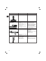
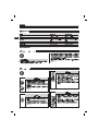
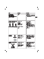
7.5 Loading the powder-actuated tool
1. Push the threaded stud into the tool threaded end first,
as far as it will go, until it is held in place in the tool.
2. Push the cartridge strip, narrow end first, into the
guideway in the grip of the tool from below, until the
full length of the cartridge strip is within the grip. When
loading a partly-used cartridge strip, pull the cartridge
strip up out of the tool from above by hand until an
unused cartridge is in place in the cartridge chamber.
7.6 Setting the fastener driving power
1. Use the power regulation guide to determine the cor-
rect driving power setting (the power regulation guide
is enclosed in the package with the threaded studs).
Perform a test fastening to verify the guideline pow-
er setting is correct.
2. If the threaded stud is not driven in to the correct posi-
tion, adjust the driving power to an appropriate set-
ting by turning the power regulation wheel.
7.7 Driving a threaded stud
1. Position the threaded stud in the predrilled hole and
then press the tool against the working surface at right
angles.
2. Pull the trigger to drive the stud.
-WARNING-
Do not attempt to redrive the same threaded stud by
firing the tool a second time.
Do not drive studs into damaged or previously used
holes.
7.8 Unloading the powder-actuated tool
1. Check to ensure that no cartridge strip is in the tool.
If there is a cartridge strip in the tool, remove it by
pulling it upwards out of the tool from above.

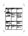
3. Rotate the black housing counterclockwise through
one complete revolution (360°). This releases the pis-
ton stop.
4. Remove the piston from the tool.
-NOTE-
If the piston is jammed in the piston guide, the complete
piston guide must be removed from the tool.
5. Unscrew and remove the black housing completely
by turning it counterclockwise.
6. Press the piston guide against the tool with the palm
of the hand.
7. Pull the complete unit away from the tool.
8. Pull the black housing away from the piston guide.
9. Ziehen Sie den Kolben aus der Kolbenführung.
8.4 Checking the piston for wear
The piston must be replaced if it is:
– badly worn
– broken
– bent (check by rolling it on a flat surface).
-WARNING-
Should the tip of the piston become worn or damaged,
do not attempt to grind it off in order to permit further
use. This may negatively affect the quality of the f astening
obtained and may result in serious damage to the tool.
8.5 Cleaning the piston
1. Clean the piston with a flat brush.
2. Spray the piston lightly with Hilti spray.
8.6 Cleaning the fastener guide
1. Clean the fastener guide with a small round brush.
2. Spray the fastener guide lightly with Hilti spray.
8.7 Cleaning the cartridge strip guideway
1. Clean the right and the left cartridge strip guideway
with the scraper supplied.
8.8 Cleaning the piston guide
1. Clean the inside of the piston guide with a round brush
and the outside with a flat brush.
2. Clean the cartridge chamber and the power regulation
bore in the end of the piston guide.
3. Spray the inside and the outside of the piston guide
lightly with Hilti spray.
8.9 Cleaning inside the housing
1. Clean the inside of the housing with the flat brush.
2. Spray the housing lightly with Hilti spray.
8.10 Assembling the tool
1. Fit the black housing onto the piston guide.
2. Pull the black housing upwards against the spring
pressure and hold it securely in this position in your
hand.
8
en
-CAUTION-
●The tool can get hot while operating.
●You could burn your hands.
●Do not disassemble the tool while it
is hot. Let the tool cool down.
8. Care and maintenance
When this type of tool is used under normal operating
conditions, dirt and residues build up inside the tool
and functionally relevant parts are also subject to wear.
Regular inspections and maintenance are thus essen-
tial in order to achieve reliable operation. We recom-
mend that the tool is cleaned and the piston and piston
brake are checked at least weekly when the tool is sub-
jected to intensive use, and at the latest after driving
2,000 fasteners.
8.1 Care of the tool
Clean the tool:
●After driving 2,000 studs
●If cartridges misfire
●If driving power is not constant
●If moving parts do not operate freely
The outer casing of the tool is manufactured from
impact-resistant plastic. The grip comprises a synthetic
rubber section. The ventilation slots must be unob-
structed and kept clean at all times. Do not permit for-
eign objects to enter the interior of the tool. Use a slight-
ly damp cloth to clean the outside of the tool at regu-
lar intervals. Do not use a spray or steam-cleaning sys-
tem for cleaning.
8.2 Maintenance
Check all external parts of the tool for damage at regu-
lar intervals and check that all controls operate proper-
ly. Do not operate the tool when parts are damaged or
when the controls do not operate properly. If necessary,
have the tool repaired at a Hilti service centre.
-CAUTION- when cleaning:
●Never use grease for the maintenance/lubrication of
parts of the tool. This may lead to malfunctions. Use
only Hilti lubricant spray or a product of comparable
quality.
●The residues deposited inside DX tools contain sub-
stances that may be injurious to your health:
– Do not inhale any dust or dirt while cleaning.
– Keep the dust or dirt away from foodstuffs.
– Wash your hands after cleaning the tool.
8.3 Disassembling the tool
1. Check to ensure that no cartridge strip is in the tool.
If there is a cartridge strip in the tool, remove it by
pulling it upwards out of the tool from above.
2. Unscrew and remove the fastener guide.

9
en
3. Fit the complete unit into the tool so that the marks on
the piston guide and on the metal housing are in align-
ment.
4. Press in the piston stops when the piston guide has
been inserted far enough for the stops to fit into the
openings at the side of the piston guide.
5. Release the black housing and screw it on to the tool
(only 1–2 turns).
6. Push in the piston as far as it will go. The piston can
be inserted only before the black housing is screwed
on fully (before the final turn). Then screw on the black
housing as far as it will go (until it engages).
7. Press the fastener guide firmly against the piston guide
and then screw it on until it engages.
8.11 Checking the tool following care and
maintenance
After carrying out care and maintenance on the tool,
check that all protective and safety devices are fitted and
that they function correctly.
-CAUTION-
The use of lubricants other than Hilti spray could dam-
age rubber parts, especially the buffer.

10
en
Cartridge falls out of the
cartridge strip
Cartridge strip melts
9. Troubleshooting
Cartridge doesn’t fire
Cartridge not transported
Cartridge strip cannot be removed
Fault Possible cause
■Damaged cartridge strip
■Carbon build-up
■Tool damaged
■Bad cartridge
■Carbon build-up
-WARNING-
Never attempt to pry a cartridge
from the magazine strip or tool.
■Tool is compressed too long
while fastening.
■Fastening frequency is too high
■Fastening frequency is too high
-WARNING-
Never attempt to pry a cartridge
from the magazine strip or tool.
Remedy
■Clean the cartridge strip guide-
way (see 24)
If the problem persists:
■Contact Hilti Repair Centre
■Let the tool cool down and then
carefully try to remove the
cartridge strip (If the problem
persists: Contact Hilti Repair
Center)
■Contact Hilti Repair Center
■Manually advance the cartridge
strip one cartridge
■If the problem occurs more often:
Clean the tool
(If the problem persists: Contact
Hilti Repair Center)
■Compress the tool only briefly
while fastening.
■Remove the cartridge strip
■Disassemble the tool for fast
cooling and to avoid possible
damage
(If the tool cannot be disassem-
bled: Contact Hilti Repair Center)
■Immediately discontinue using
the tool
■Remove cartridge strip
■Let the tool cool down
■Clean the tool and remove loose
cartridge.
(If it is impossible to disassemble
the tool: Contact Hilti Repair
Center)
■Tool overheated because of high
setting rate
■Tool damaged
-WARNING-
Never attempt to pry a cartridge
from the magazine strip or tool.

11
en
The operator notices:
■increased contact pressure
■increased trigger force
■power regulation stiff to adjust
■cartridge strip is difficult to
remove
Fault Possible cause
■Carbon build-up
Remedy
■Clean the tool
■Check that the correct cartridges
are used (see 1.2) and that they
are in faultless condition.
Threaded studs driven to different
depths or sealing washer pres-
sure/contact not constant
■Hole not deep enough
■Piston broken or damaged
■Fastener guide damaged
■Damaged protective cover
■Tool misfires
■Wrong driving power setting
■Carbon build-up
■Drill to correct depth
=> visible ring .
■Replace the piston.
■Replace the fastener guide.
■Replace the protective cover.
■Change the cartridge strip (take a
strip from a new, dry package if
necessary). Clean the cartridge
strip guideway and cartridge
chamber.
■Check driving power using the
power regulation guide.
■Clean the tool.
Damage to the
painted surface on
the underside of the
base material
■Stud driven too deeply
■Dirt or foreign matter in the hole
■Steel base material too thin
(< 8 mm)
■Hole not deep enough
■Reduce driving power (power
regulation).
■Remove liquids, debris, or other
foreign matter from the hole
before installing the stud.
■Drive studs only on steel base
material ≥ 8 mm.
■Drill to correct depth
=> visible ring .
Threaded stud doesn’t hold in the
base material when torque is
applied
■Dirt or foreign matter in the hole
■Hole not deep enough
■Hole damaged or previously used
■Wrong drill bit used
■Too much torque applied
■Remove liquids, debris, or other
foreign matter from the hole
before installing the stud.
■Drill to correct depth => visible
ring .
■Drill new hole.
■Use appropriate drill bit
■Use appropriate amount of
torque (see 7.2.1 Recommended
torque)

12
en
The thread on the stud is
damaged
Fault Possible cause
■Fastener guide damaged
Remedy
■Replace the fastener guide.
Stud doesn’t hold in the base
material
■Steel base material too thin
(< 8 mm)
■Hole damaged or previously used
■Driving power too low
■Hole not deep enough
■Wrong drill bit used
■Dirt/debris in hole
■Drive studs only on steel base
material ≥ 8 mm.
■Drill new hole.
■Increase driving power.
■Drill to correct depth
=> visible ring .
■Use correct drill bit
■Remove liquids, debris or other
foreign matter from the hole
before installing the stud.
Piston jams in the piston guide ■Damaged piston
■Carbon build-up
■Remove the cartridge strip
■Kolbenführung
■Check the piston and replace it if
necessary
■Clean the tool
Trigger can’t be pulled ■Tool not pressed fully against the
work surface
■Piston fitted incorrectly
■Tool defective
■Press the tool fully against the
work surface.
■Fit the piston correctly.
■Contact your Hilti Center.

13
en
10. Disposal
Hilti warrants that the tool supplied is free of defects
in material and workmanship. This warranty is valid so
long as the tool is operated and handled correctly,
cleaned and serviced properly and in accordance with
the Hilti Operating Instructions, and the technical sys-
tem is maintained. This means that only original Hilti
consumables, components and spare parts, or other
products of equivalent quality, may be used in the tool.
This warranty provides the free-of-charge repair or
replacement of defective parts only over the entire lifes-
pan of the tool. Parts requiring repair or replacement
as a result of normal wear and tear are not covered by
this warranty.
Additional claims are excluded, unless stringent
national rules prohibit such exclusion. In particular,
Hilti is not obligated for direct, indirect, incidental
or consequential damages, losses or expenses in
connection with, or by reason of, the use of, or inabil-
ity to use the tool for any purpose. Implied warranties
of merchantability or fitness for a particular purpose
are specifically excluded.
For repair or replacement, send tool or related parts
immediately upon discovery of the defect to the address
of the local Hilti marketing organization provided.
This constitutes Hilti's entire obligation with regard to
warranty and supersedes all prior or contemporane-
ous comments and oral or written agreements con-
cerning warranties.
11. Manufacturer's warranty – DX Tools
12. EC declaration of conformity (original)
Most of the materials from which Hilti power actuated
tools are manufactured can be recycled. The materi-
als must be correctly separated before they can be recy-
cled. In many countries, Hilti has already made arrange-
ments for taking back your old powder actuated tools
for recycling. Please ask your Hilti customer service
department or Hilti sales representative for further infor-
mation.
Should you wish to return the power actuated tool your-
self to a disposal facility for recycling, proceed as fol-
lows: Dismantle the tools as far as possible without
the need for special tools.
Designation: Powder-actuated tool
Type: DX 351BT/BTG
Year of design: 2003
We declare, on our sole responsibility, that this product
complies with the following directives and standards:
2006/42/EC, 2011/65/EU.
Hilti Corporation, Feldkircherstrasse 100,
FL-9494 Schaan
Norbert Wohlwend Tassilo Deinzer
Head of Quality & Processes Management Head BU Measuring Systems
BU Direct Fastening BU Measuring Systems
08/2012 08/2012
Technical documentation filed at:
Hilti Entwicklungsgesellschaft mbH
Zulassung Elektrowerkzeuge
Hiltistrasse 6
86916 Kaufering
Deutschland

14
en
13. Confirmation of CIP testing
The Hilti DX351BT and DX351BTG have been system
and type tested. As a result, the tools bear the square-
shaped PTB approval mark showing approval number
S 807. In this way, Hilti guarantees compliance with the
approved type.
Unacceptable/inadmissible defects, deficiencies, etc.
that are determined during use of the tool must be report-
ed to the manager responsible at the approval authori-
ty (PTB) and to the Office of the Permanent International
Commission (C.I.P.).
14. Health and safety of the user
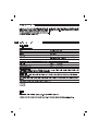
Noise information
The following table provides noise measurement information:
Powder-actuated tool
Type: DX 351-BT / DX 351 BTG
Model: Serial production
Caliber: 6.8/11 brown
Power setting: 3
Application: Fastening of X-BT M10-24-6 onto pre-drilled steel
platting 8 mm thick
Declared measured values of noise characteristics according to 2006/42/EC Machinery Directive in
conjunction with E DIN EN 15895
Noise (power) level: LWA, 1s1109 dB(A)
Emission noise-pressure level in the work station: LpA, 1s2105 dB(A)
Peak sound pressure emission level: LpC, peak3136 dB(C)
Operation and set-up conditions:
Set-up and operation of the pin driver in accordance with E DIN EN 15895-1 in the semi-anechoic test room of
Müller-BBM GmbH. The ambient conditions in the test room conform to DIN EN ISO 3745.
Testing procedure:
Enveloping surface method in anechoic room on reflective surface area in accordance with E DIN EN 15895, DIN
EN ISO 3745 and DIN EN ISO 11201.
NOTE: The noise emissions measured and the associated measurement uncertainty represent the upper limit for
the noise values to be expected during the measurements.
Variations in operating conditions may cause deviations from these emission values.
1± 2 dB (A)
2± 2 dB (A)
3± 2 dB (C)
Vibration
The declared total vibration value according to 2006/42/EC does not exceed 2.5 m/s2.
Further information regarding the health and safety of the user can be found at the Hilti web site: www.hilti.com/hse
La page est en cours de chargement...
La page est en cours de chargement...
La page est en cours de chargement...
La page est en cours de chargement...
La page est en cours de chargement...
La page est en cours de chargement...
La page est en cours de chargement...
La page est en cours de chargement...
La page est en cours de chargement...
La page est en cours de chargement...
La page est en cours de chargement...
La page est en cours de chargement...
La page est en cours de chargement...
La page est en cours de chargement...
La page est en cours de chargement...
La page est en cours de chargement...
La page est en cours de chargement...
La page est en cours de chargement...
La page est en cours de chargement...
La page est en cours de chargement...
La page est en cours de chargement...
La page est en cours de chargement...
La page est en cours de chargement...
La page est en cours de chargement...
La page est en cours de chargement...
La page est en cours de chargement...
La page est en cours de chargement...
La page est en cours de chargement...
La page est en cours de chargement...
La page est en cours de chargement...
La page est en cours de chargement...
La page est en cours de chargement...
La page est en cours de chargement...
La page est en cours de chargement...
La page est en cours de chargement...
La page est en cours de chargement...
La page est en cours de chargement...
La page est en cours de chargement...
La page est en cours de chargement...
La page est en cours de chargement...
La page est en cours de chargement...
La page est en cours de chargement...
La page est en cours de chargement...
La page est en cours de chargement...
La page est en cours de chargement...
La page est en cours de chargement...
La page est en cours de chargement...
La page est en cours de chargement...
La page est en cours de chargement...
La page est en cours de chargement...
La page est en cours de chargement...
La page est en cours de chargement...
La page est en cours de chargement...
La page est en cours de chargement...
La page est en cours de chargement...
La page est en cours de chargement...
La page est en cours de chargement...
La page est en cours de chargement...
La page est en cours de chargement...
La page est en cours de chargement...
-
 1
1
-
 2
2
-
 3
3
-
 4
4
-
 5
5
-
 6
6
-
 7
7
-
 8
8
-
 9
9
-
 10
10
-
 11
11
-
 12
12
-
 13
13
-
 14
14
-
 15
15
-
 16
16
-
 17
17
-
 18
18
-
 19
19
-
 20
20
-
 21
21
-
 22
22
-
 23
23
-
 24
24
-
 25
25
-
 26
26
-
 27
27
-
 28
28
-
 29
29
-
 30
30
-
 31
31
-
 32
32
-
 33
33
-
 34
34
-
 35
35
-
 36
36
-
 37
37
-
 38
38
-
 39
39
-
 40
40
-
 41
41
-
 42
42
-
 43
43
-
 44
44
-
 45
45
-
 46
46
-
 47
47
-
 48
48
-
 49
49
-
 50
50
-
 51
51
-
 52
52
-
 53
53
-
 54
54
-
 55
55
-
 56
56
-
 57
57
-
 58
58
-
 59
59
-
 60
60
-
 61
61
-
 62
62
-
 63
63
-
 64
64
-
 65
65
-
 66
66
-
 67
67
-
 68
68
-
 69
69
-
 70
70
-
 71
71
-
 72
72
-
 73
73
-
 74
74
-
 75
75
-
 76
76
-
 77
77
-
 78
78
-
 79
79
-
 80
80


Hilti DX 351 BT Manuel utilisateur
- Catégorie
- Cloueuse
- Taper
- Manuel utilisateur
dans d''autres langues
- English: Hilti DX 351 BT User manual