Current Arize Element L1000 Gen 2 Guide d'installation

Taper
Guide d'installation
Element® L1000 Gen2
Horticulture LED Lighting System
HORT158 | DOC-2000991
EN For the latest European install guides and safety
information: https://www.gecurrent.com/eu-en/
indoor-lighting/horticulture-led-grow-lights
BG Българската версия на инструкциите за
инсталаця и информация за безопасност могат
да бъдат намерени на следния адрес: https://
www.gecurrent.com/eu-en/indoor-lighting/
horticulture-led-grow-lights
CS Návod k montáží a bezpečnostní informace v
češtině najdete zde: https://www.gecurrent.com/
eu-en/indoor-lighting/horticulture-led-grow-
lights
DA Den danske version af installationsvejledningen
og sikkerhedsoplysninger kan ndes på følgende
placering: https://www.gecurrent.com/eu-en/
indoor-lighting/horticulture-led-grow-lights
DE Die deutsche Version der Installationsanleitung
und Sicherheitsinformationen nden Sie in
folgendem Verzeic: https://www.gecurrent.com/
eu-en/indoor-lighting/horticulture-led-grow-
lights
EL Μπορείτε να βρείτε την ελληνική εκδχή των
οδηγιών νγκατάστασης και των πληροφοριών
ασφάλειας στην εξής τοποθεσία: https://
www.gecurrent.com/eu-en/indoor-lighting/
horticulture-led-grow-lights
ES La versión española de las instrucciones de
instalación y la información sobre seguridad
puede encontrarse en la siguiente ubicación:
https://www.gecurrent.com/eu-en/indoor-
lighting/horticulture-led-grow-lights
ET Eestikeelse paigaldusjuhendi ja ohutusnñuded
leiate aadressilt: https://www.gecurrent.com/eu-
en/indoor-lighting/horticulture-led-grow-lights
FI Asennusohjeiden ja turvallisuustietojen
suomenkielinen versio löytyy seuraavasta
paikasta: https://www.gecurrent.com/eu-en/
indoor-lighting/horticulture-led-grow-lights
FR La version française des instructions
d’installations et information de sécurité
est disponible à l’adresse suivante: https://
www.gecurrent.com/eu-en/indoor-lighting/
horticulture-led-grow-lights
HR Hrvatska verzija priručnika za ugradnju i
sigurnosnih informacija nalazi se na sljedečoj
lokaciji: https://www.gecurrent.com/eu-en/
indoor-lighting/horticulture-led-grow-lights
HU A telepítési útmutató és a biztnosági információk
magyar nyelvű változata az alábbi címen
található: https://www.gecurrent.com/eu-en/
indoor-lighting/horticulture-led-grow-lights
IT La versione italiana del manuale di installazione
e sicurezza può essere reperita nella seguente
sezione: https://www.gecurrent.com/eu-en/
indoor-lighting/horticulture-led-grow-lights
LT Lietuvišką diegimo instrukcijos ir saugos
informacijos versiją galima rasti šioje vietoje:
https://www.gecurrent.com/eu-en/indoor-
lighting/horticulture-led-grow-lights
LV Uzstādīšanas instrukciju un drošības informāciju
latviešu valodā var atrast šeit: https://www.
gecurrent.com/eu-en/indoor-lighting/
horticulture-led-grow-lights
NL De Nederlandse versie van de installatie-
instructies en veiligheidsinformatie kan op de
volgende locatie worden gevonden: https://
www.gecurrent.com/eu-en/indoor-lighting/
horticulture-led-grow-lights
PL Polską wersję instrukcji instalacji oraz informacje
dotyczące bezpieczeństwa można znaleźć w
następującej lokalizacji: https://www.gecurrent.
com/eu-en/indoor-lighting/horticulture-led-
grow-lights
PT A versão em Português das instruções de
instalação e das informações de segurança pode
ser encontrada na seguinte localização: https://
www.gecurrent.com/eu-en/indoor-lighting/
horticulture-led-grow-lights
RO Versiunea în limba românǎ a instrucţiunilor de
instalare şi a informaţiilor de siguranţǎ pot 
gǎsite la: https://www.gecurrent.com/eu-en/
indoor-lighting/horticulture-led-grow-lights
SV Ni hittar den svenska versionen
av installationsanvisningarna och
säkerhetsinformationen på följande plats: https://
www.gecurrent.com/eu-en/indoor-lighting/
horticulture-led-grow-lights
SL Previdnostna opozorila in varnostne informacije
so na zadnji strani vodnika za namestitev. Pred
začetkom namestitve izdelka jih skrbno preberite:
https://www.gecurrent.com/eu-en/indoor-
lighting/horticulture-led-grow-lights
SK Slovenskú verziu montažnej príručky a
bezpečnostnŷch instrukcií nájdete na
nasledujúcej lokalite: https://www.gecurrent.com/
eu-en/indoor-lighting/horticulture-led-grow-
lights
For the UL installation guide and safety information, please continue to page 2
Pour la version UL des instructions d’installations et information de sécurité, continuez à la page 2
2
Arize Element® L1000 Gen2 Installation Guide
BEFORE YOU BEGIN / AVANT DE COMMENCER
Read these instructions completely and carefully. Lisez attentivement ces instructions dans leur intégrali.
For Commercial or Industrial use only.
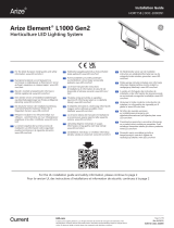
0°C
40°C
Suitable for operation in an ambient temperature
between 32°F (0°C) and 104°F (40°C).
A mechanical ventilation or cooling system is
required to maintain the temperature within the
growing space below 113°F (45°C) when the light
module is in operation.
Opération compatible avec un environnement à temperature
ambiante controlée entre 32°F (0°C) et 104°F (40°C).
l’utilisation d’un système de contrôle de la température sera
nécessaire pour garder la serre sous les 113°F (45°C) lorsque le
luminaire est en function.
WARNING / AVERTISSEMENT
RISK OF ELECTRIC SHOCK
Turn power o before installation, inspection, cleaning or removal. And
follow appropriate lock out/tag out safety procedure.
Properly ground electrical enclosure.
Follow all National Electric Codes (NEC) and local codes.
This product must be installed in accordance with the applicable
installation code by a person familiar with the construction and
operation of the product and the hazards involved.
The installation and associated structures are subject to approval
by the authority having jurisdiction.
Use only with components identied in this document.
Suitable for dry, damp, and wet locations; Do not immerse any
component.
Wear suitable Personal Protective Equipment (PPE) during
installation/maintenance. Highly recommend safety glasses,
helmet and leather glove for luminaire mounting.
Luminaire design for Greenhouse only.
RISK OF FIRE
Minimum 12 inch distance from light module & driver to any
combustible material.
Minimum 6 inch clearance between, light module & driver, light
module & light module, driver & driver.
The light module shall be installed lens down with a minimum 5
inch distance to anything below.
All cables including connectors shall not be concealed or extended
through a wall, oor, ceiling, or other parts of the building structure;
located above a suspended ceiling or dropped ceiling; permanently
axed to the building structure.
Cables shall be routed so that they are not subject to strain and
are protected from physical damage; visible over their entire
length; and used within their rated ampacity as determined for
the maximum temperature of the installed environment specied
in the instructions.
For safe operation, and to maximize the longevity of the
luminaire; ensure that the light module and driver are clean and
free of dirt, dust, oil, or any other debris. Do not apply any kind
of lm on the lens or otherwise cover the driver or light engine
in any way.
RISQUE DE CHOC ELECTRIQUE
Coupez l’alimentation avant l’inspection, l’installation ou la désinstallation.
Reliez correctement le boîtier électrique à la mise à la terre.
Suivre tous les codes électriques locaux applicables.
Ce produit doit être installé selon le code d’installation pertinent,
par une personne qui connaît bien le produit et son fonctionnement
ainsi que les risques inhérents.
L’installation et les structures associées sont soumises à
l’approbation des autorités compétentes.
Utilisez uniquement avec les composants identiés dans ce document.
Convient aux endroits secs, humides et mouillés. Ne doit pas être immergé.
Portez les équipements de protection individuelle appropriés
pendant l’installation et la maintenance. L’utilisation de lunettes
de sécurité, d’un casque et des gants de cuir pour le montage du
luminaire est fortement recommandée.
Luminaire conçu pour serres seulement.
RISQUE D’INCENDIE
Distance minimale de 12 pouces entre l’équipement d’éclairage et
toute matière combustible.
Distance minimale de 6 pouces entre tout équipement d’éclairage,
module d’éclairage ou module d’alimentation.
Le luminaire doit être installé avec l'objectif pointé vers le bas avec
une distance minimale de 5 pouces entre le luminaire et tout objet.
Les câbles et connecteurs ne doivent pas être dissimulés à l’intérieur,
ou passer à travers, d’un mur, d’un plancher, d’un plafond ou de
toute autre partie de la structure du bâtiment; ne doivent pas être
placés au-dessus d’un plafond suspendu; ne doivent pas faire partie
intégrante de la structure du bâtiment.
Les câbles doivent être installés de façon à être protégés contre
l’étirement et tout autre bris physique; visibles sur toute leur
longueur; utilisés dans la limite de leur courant admissible,
déterminée pour les limites de température de l’environnement
spéciées dans le guide d’instruction.
Pour une opération sécurisée et pour maximiser la longévité
du luminaire; S'assurer que le module d'éclairage et le module
d'alimentation sont propres et sans saleté, poussière, huile ou
autres débris. Ne pas appliquer tout type de lm sur les lentilles et
ne pas couvrir le module d'alimentation ou le module d'éclairage de
quelconque manière.
3
Arize Element® L1000 Gen2 Installation Guide
12
3
4
6
5
Driver Specications
Light Module Specications
Description Weight Input Voltage
GEPSC240-680D-BDGGL 3.2 kg (7 lbs) 120-277 VAC
GEPSC240-680D-BGJGL 3.2 kg (7 lbs) 277-480 VAC
Light Module Part Number Order Code Weight
System Input Current [A]
Low Voltage Driver
@ 120/208/240/277VAC
System Input Current [A]
High Voltage Driver
@ 277/347/480VAC
GEHE-HPPRB2A / GEHE-HPPRW2A GEHEHPPRxxN2xx 4.5 kg (10 lbs) 4.9/2.9/2.5/2.2 2.2/1.8/1.3
GEHE-HPPBB2A / GEHE-HPPBW2A GEHEHPPBxxN2xx 4.5 kg (10 lbs) 5.2/3.1/2.7/2.3 2.3/1.9/1.4
GEHE-HPKTB2A / GEHE-HPKTW2A GEHEHPKTxxN2xx 4.5 kg (10 lbs) 5.1/3.0/2.6/2.3 2.3/1.8/1.4
GEHE-HPKRB2A / GEHE-HPKRW2A GEHEHPKRxxN2xx 4.5 kg (10 lbs) 5.3/3.1/2.7/2.4 2.3/1.9/1.4
GEHE-HPKBB2A / GEHE-HPKBW2A GEHEHPKBxxN2xx 4.5 kg (10 lbs) 5.4/3.2/2.8/2.4 2.4/1.9/1.4
GEHE-HPKFB2A / GEHE-HPKFW2A GEHEHPKFxxN2xx 4.5 kg (10 lbs) 5.4/3.3/2.8/2.4 2.4/1.9/1.4
GEHE-HBRIB2A / GEHE-HBRIW2A GEHEHBRIxxN2xx 4.5 kg (10 lbs) 5.5/3.2/2.8/2.5 2.4/2.0/1.5
GEHE-HBRVB2A / GEHE-HBRVW2A GEHEHBRVxxN2xx 4.5 kg (10 lbs) 5.8/3.4/2.9/2.6 2.5/2.1/1.5
GEHE-VPPRB2A / GEHE-VPPRW2A GEHEVPPRxxN2xx 4.5 kg (10 lbs) 4.5/2.6/2.3/2.0 2.0/1.6/1.2
GEHE-VPPBB2A / GEHE-VPPBW2A GEHEVPPBxxN2xx 4.5 kg (10 lbs) 4.8/2.8/2.4/2.1 2.1/1.7/1.3
GEHE-VPKTB2A / GEHE-VPKTW2A GEHEVPKTxxN2xx 4.5 kg (10 lbs) 4.6/2.7/2.4/2.1 2.0/1.7/1.2
GEHE-VPKRB2A / GEHE-VPKRW2A GEHEVPKRxxN2xx 4.5 kg (10 lbs) 5.0/2.9/2.5/2.2 2.2/1.8/1.3
GEHE-VPKBB2A / GEHE-VPKBW2A GEHEVPKBxxN2xx 4.5 kg (10 lbs) 5.1/3.0/2.6/2.3 2.2/1.8/1.4
GEHE-VPKFB2A / GEHE-VPKFW2A GEHEVPKFxxN2xx 4.5 kg (10 lbs) 4.8/2.8/2.5/2.2 2.1/1.7/1.3
GEHE-CPKTB2A / GEHE-CPKTW2A GEHECPKTxxN2xx 4.5 kg (10 lbs) 6.1/3.5/3.0/2.6 2.6/2.1/1.5
GEHE-CPKRB2A / GEHE-CPKRW2A GEHECPKTxxN2xx 4.5 kg (10 lbs) 6.1/3.5/3.0/2.6 2.6/2.1/1.5
System Component Parts
Please refer to order logic to determine included or accessory
AC cable
Driver
Driver Bracket
Hanger (2x)
Light Module Brackets (2x)
Light Module
1
2
3
4
5
6
4
Arize Element® L1000 Gen2 Installation Guide
Mounting Accessories Specications
Description Detailed Description Weight
GEMB-WAS1 Wire bracket mounting kit, square 1-5/8" (41mm) 0.4 kg (0.9 lbs)
GEMB-WAA1 Wire bracket oset mounting kit, square 1-5/8" (41mm) 0.6 kg (1.3 lbs)
GEMB-WAS2 Wire bracket mounting kit, square 2-3/4" (70mm) 0.4 kg (0.9 lbs)
GEMB-CBH1 18" (457mm) cable universal mounting kit 0.1 kg (0.2 lbs)
GEMB-CBH2 60" (1524mm) cable universal mounting kit 0.1 kg (0.2 lbs)
GEMB-PAU1 Perpendicular (90°) universal mounting kit 0.5 kg (1.1 lbs)
Description Detailed Description
GECA60C16-OL04B AC Leader Cable, 4ft, UL
GECA60C16-8L04B AC Leader Cable, 4ft, 16AWG, NEMA L8-20, UL
GECA60C16-7L04B AC Leader Cable, 4ft, 16AWG, NEMA L7-15, UL
GECA30A16-HL04B AC Leader Cable, 4ft, 16AWG, NEMA L7-20P, UL
GECA60C16-5L04B AC Leader Cable, 4ft, NEMA 5-15, UL
GECA60FNA-NL00B AC Field Installable Connector, UL and CE (Wieland P.N. 96.031.4155.7)
GECA30G14-EN03B DC Inter-Connection Cable, 3ft (914mm), UL and CE
GECA30G14-EN06B DC Inter-Connection Cable, 6ft (1828mm), UL and CE
GECA30H20-OO03B Dimming cable, 3ft (914mm), UL and CE
Interconnection Cable Specications
Sample Base Installation Diagram
Unistrut
Structural member
AC line
Plants Plants
Top Light Module
Structure
DRIVER
DRIVERDRIVER
CAUTION / ATTENTION
Installation instructions and specications for
accessories can be found in the accessory package.
Les instructions d’installation et spécications pour les accessoires se
retrouvent dans le kit d’accessoires.
5
Arize Element® L1000 Gen2 Installation Guide
1 Installation of the Light Module
Install brackets at location A.
Press down on bracket until hooks snap into
place. Ensure bracket hooks catch bottom
edge of heatsink.
Slide down bracket along channels.
SNAP! SNAP!
If not preassembled, install light module brackets on light module.
1.1 Installation of Module Brackets
1
3
2
A
A
6
Arize Element® L1000 Gen2 Installation Guide
Place light module hanger
over structural member and
snap hanger in place.
Hang one xture bracket on one hook, hang opposite xture
bracket onto other hook by pressing hanger arms together.
Based on the cross section of the structural member select the correct hanger or mounting cable.
1.2 Selection of Mounting Hardware
1.3 Installation with Standard and Oset Hangers
SNAP!
Use standard hanger 1-5/8" (41mm)
OR
Oset hanger 1-5/8" (41mm)
to clear the bottom of the Unistrut
Use standard hanger
2-3/4" (70mm)
Use 18" (0.5m) or 60" (1.5m)
universal cable
OR
Perpendicular (90°)
universal mounting kit
Unistrut 1-5/8" (41mm) Square 2-3/4" (70mm) Other Structural Members
1 2
7
Arize Element® L1000 Gen2 Installation Guide
1.4 Installation with Universal Cables
Wrap loop end of cable over structural member.
Insert hook through loop end.
Attach hooks to light module brackets. Ensure
hook gate is closed.
Loop Hook
1.5 Installation with Perpendicular 90° Universal Mounting Kit
Kits Contents (SKU: 93139057)
Tools Required
1x Worm Drive Clamp
1x Metal Bracket
2x Carabiners
5/16” hex socket or
at-blade screwdriver
6 ft. Inter-connection
4x 18 in. Universal Cables
1 2
123
4
1
2
3
4
5
5
8
Arize Element® L1000 Gen2 Installation Guide
Installation Steps for Perpendicular 90° Universal Mounting Kit
First determine which 2 slots on
the metal bracket most closely
correspond to the structural
member width. Insert strap of
the worm drive clamp through
the rst slot of the metal
bracket from the top.
Place the metal bracket on
top of the structural member
and wrap the strap around
the bottom of the structural
member and back up through
the second slot.
Secure the metal bracket on
to the top of the structural
member by inserting the
strap into the open end of the
clamp and tightening down
the screw.
Attach a carabiner to each
side of the metal bracket.
Attach a support cable to each
carabiner and ensure the gates
are closed.
Attach other end of cables
to light module. Ensure hook
gates are closed.
1.6 Installation with Custom Brackets
If you choose to use your own
custom mounting method, attach
to points A.
1 2 3
4 5 6
A
A
9
Arize Element® L1000 Gen2 Installation Guide
2 Installation of the Driver
Orient driver perpendicular to the bracket.
Bracket
Squeeze bracket arms together & slide
hook into rst driver mounting hole.
Let driver swing free upright & ensure
hooks on both sides are correctly engaged.
Ensure rst end of bracket hook is lined up with
oval mounting hole of driver.
Repeat on opposite driver mounting hole.
If not preassembled, install driver bracket onto driver.
2.1 Installation of Driver Bracket
1
3
5
2
4
10
Arize Element® L1000 Gen2 Installation Guide
2.2 Selection of Mounting Hardware
Based on the cross section of the structural member select the correct hanger or mounting cable.
Hang brackets of driver module
onto hanger and push down until
brackets snap into place.
Hang driver bracket from one hook, then hang other driver
bracket end by pressing hanger arms together.
2.3 Installation with Hangers
SNAP!
Use standard hanger 1-5/8" (41mm)
OR
Oset hanger 1-5/8" (41mm)
to clear the bottom of the Unistrut
Use standard hanger
2-3/4" (70mm)
Use 18" (0.5m) universal cable
Unistrut 1-5/8" (41mm) Square 2-3/4" (70mm) Other Structural Members
1 2
11
Arize Element® L1000 Gen2 Installation Guide
2.4 Installation with Universal Cables
2.5 Installation with Custom Brackets
Wrap loop end of cable over structural member.
Insert hook through loop end.
Attach hooks to oval driver mounting holes.
Ensure hook gate is closed.
If you choose to use your own
custom mounting method,
attach to oval driver mounting
holes A and B for hanging.
No side forces should be
applied to mounting holes
A and B.
Loop Hook
1 2
B
A
12
Arize Element® L1000 Gen2 Installation Guide
3.2 Connect the AC Input
Select the correct AC input leader cable.
Leader cable to 4 ft.
open lead UL or CE
Leader cable with
Nema 5-15P plug
Leader cable with
Nema L7-15P plug
Leader cable with
Nema L8-20P plug
3 Electrical Connections
3.1 Connect the Driver Output to Light Module
NOTE 2: To disassemble connectors, turn locking ring 1/8 of a turn counter-clockwise and separate connectors.
NOTE 1: Use 3 ft. or 6 ft. extension cables if driver and light module are more than 2 ft. apart.
Align keying features of
larger output connector on
driver with connector on light
module cable.
Push connectors together until
the lock ring has snapped into
place and a click is heard.
Recommended: secure light
module cable.
1 2 3
CLICK!
Driver connections
DC Output
Dimming
Amphenol P/N:
AD-03PMMS-QC8001 / Male
AC Input
Weiland P/N: 96.032.1055.7 / Male
13
Arize Element® L1000 Gen2 Installation Guide
3.2.2 Using Custom AC Inputs
3.2.1 Connect the Driver Input
CLICK!
AC line
To driver input
Connect the green wire to the incoming ground
conductor. Connect the black wire to Line 1 and white
wires to Neutral or Line 2 of the incoming AC line.
Pin Line-to-Line Voltage Line-to-Neutral Voltage
1 L2 L1 L1 L1 L2 L3
2L3 L2 L3 N N N
PE PE PE PE PE PE PE
L=Line / N=Neutral / PE=Protective Earth
If you choose to use your own custom
AC input connection, use a Wieland
RST20i3 green connector (96.031.4055.7
OR 96.031.4155.7 OR 96.031.0055.7 OR
96.031.1055.7) and plug into the male AC
connector of the driver.
3.2.3 Connecting Driver to AC Line
NOTE: To disassemble connectors, insert
and twist a small blade screwdriver and
then separate connectors.
Align keying features on driver
with connector on the selected
leader cable.
Push connectors together until
a click is heard.
Recommended: secure AC
input leader cable.
1 2 3
WARNING / AVERTISSEMENT
RISK OF ELECTRIC SHOCK
Turn power OFF before inspection, installation or removal.
RISQUE DE CHOC ELECTRIQUE
Coupez l’alimentation avant l’inspection, l’installation ou la désinstallation.
Connector pin-out
1
2
PE
>PA<
14
Arize Element® L1000 Gen2 Installation Guide
3.3 Connection Schematic
4 Connecting Wired Dimming (Optional)
WARNING /
AVERTISSEMENT
Ambient temperature surrounding each
driver must be lower than 113°F (45°C).
/ La température ambiante autour de
chaque module d’alimentation ne doit pas
excéder 113°F (45°C).
Driver Input Wire Colors
Black = Line 1
White = Neutral or Line 2
Yellow/Green = Ground
Light module
AC line Use proper circuit protection level
Optional 3’ or 6’ inter-connection cable
NOTE: Maximum cumulative length of inter-connection cable is 12 feet.
NOTE: Arize L1000 dimming allows user to adjust the light output from 0%/10-100%. When set to 0%, the system will enter standby mode,
consuming 0.5-1.5W and LEDs may remain very faintly lit. If 0 light is preferred, switch o the unit via the mains (AC line).
Driver
*White = Neutral or Line 2
* * *
Driver Driver Driver Driver
N
3-Phase Y
REPEAT FOR ENTIRE CIRCUIT BALANCING OUT EACH PHASE
3-Phase ∆
L3
L2
L1
Driver Driver
Green
Green
Green
Green
Green
Green
Black
Black
Black
Black
Black
Black
White
White
White
White
White
White
Dimming
Cable
Purple
Black/White (12V)*
Pink
Dimming
Switch
+ (0-10V)
- (0-10V)
WARNING / AVERTISSEMENT
RISK OF ELECTRIC SHOCK
Turn power o before installation, inspection, cleaning or removal. And
follow appropriate lock out/tag out safety procedure.
This product must be installed in accordance with the applicable
installation code by a person familiar with the construction and
operation of the product and the hazards involved.
RISQUE DE CHOC ELECTRIQUE
Coupez l’alimentation avant l’inspection, l’installation ou la
désinstallation.
Ce produit doit être installé selon le code d’installation
pertinent, par une personne qui connaît bien le produit et son
fonctionnement ainsi que les risques inhérents.
Remove cap from dimming
connector.
Plug dimming cable: align
keying features and push
connectors together until lock
ring has snapped into place
and a click is heard. To remove
dimming cable, turn locking ring
1/8 of a turn counter-clockwise
and separate connectors.
Connect the appropriate wiring
to Dim + (0-10V) and Dim –
(0-10V) from driver. Insulate
the black wire. Follow dimming
switch instructions for rest of
connection.
*The black/white wire is a 12V
auxiliary output that can support
up to 250mA of current.
1 2 3
Arize Element® L1000 Gen2 Installation Guide
Electrical products must not be thrown out with domestic waste. They must be taken to
a communal collecting point for environmentally friendly disposal in accordance with
local regulations. Contact your local authorities or stockist for advice on recycling. The
packaging material is recyclable. Dispose of the packaging in an environmentally friendly
manner and make it available for the recyclable material collection-service.
RISK GROUP 1 - CAUTION** / ATTENTION - RAYONNEMENT LUMINEUX GROUPE 1**
Possibly hazardous optical radiation emitted from this product. Do not stare at operating lamp. May be harmful to the eyes.
Le rayonnement lumineux émis par ce produit est potentiellement dangereux. Ne pas regarder la lumière émise
directement car elle pourrait occasionner des dommages aux yeux.
For the latest install guides for your product go to:
https://www.gecurrent.com/horticulture
Visit www.LED.com
Call us today! 1-888-694-3533
Email us:
arize.suppor[email protected]
These photobiological safety markings are based on testing of the light output characteristic of a single horticultural luminaire.
Increased exposure risk to facility personnel may be present depending upon the number of horticultural luminaires and their
placement and/or positioning within the plant growth facility.
It is the responsibility of the plant growth facility to address these risks at the facility level and to ensure that people entering the
plant growth areas while the lights are on, are aware of these risks and that appropriate safeguards are in place.
Ces avertissements de sécurité photobiologiques sont basés sur des tests du rendement lumineux d'un seul luminaire horticole.
Les employés risquent de sourir d'une exposition accrue selon le nombre de luminaires horticoles et leur placement et / ou
positionnement au sein de la serre / chambre de culture.
Il relève de la responsabilité de l'opérateur de l'installation de gérer les risques au niveau de l'installation et de s'assurer que les
personnes qui pénètrent dans les zones de croissance des plantes pendant que les lumières sont allumées soient conscientes des
risques et que des mesures de protection appropriées soient en place.
Save These Instructions
Use only in the manner intended by the manufacturer. If you have any questions, contact the manufacturer.
This device complies with part 15 of the FCC Rules. Operation is subject to the following two conditions: (1) This device may not cause harmful interference,
and (2) this device must accept any interference received, including interference that may cause undesired operation.
NOTE: This equipment has been tested and found to comply with the limits for a Class A digital device, pursuant to part 15 of the FCC Rules. These limits
are designed to provide reasonable protection against harmful interference when the equipment is operated in a commercial environment. This equipment
generates, uses, and can radiate radio frequency energy and, if not installed and used in accordance with the instruction manual, may cause harmful
interference to radio communications. Operation of this equipment in a residential area is likely to cause harmful interference in which case the user will be
required to correct the interference at his own expense.
This Class [A] RFLD complies with the Canadian standard ICES-005. /CeDEFR de la classe [A] est conforme à la NMB-005 du Canada.
gecurrent.com/arize
© 2022 Current Lighting Solutions, LLC. All rights reserved. Information and specications subject to change
without notice. All values are design or typical values when measured under laboratory conditions.
Page 15 of 15
(Rev 08/12/22) 99009071
HORT158 | DOC-2000991
  • Page 1 1
  • Page 2 2
  • Page 3 3
  • Page 4 4
  • Page 5 5
  • Page 6 6
  • Page 7 7
  • Page 8 8
  • Page 9 9
  • Page 10 10
  • Page 11 11
  • Page 12 12
  • Page 13 13
  • Page 14 14
  • Page 15 15

Current Arize Element L1000 Gen 2 Guide d'installation

Taper
Guide d'installation