NuTone NM100WH Instructions Manual
- Catégorie
- Systèmes d'interphone de porte
- Taper
- Instructions Manual

MODEL NM100WH
Page 1
CAUTION
WARNING
TO REDUCE THE RISK OF FIRE, ELECTRIC SHOCK, OR
INJURY TO PERSONS, OBSERVE THE FOLLOWING:
1. Read all instructions carefully before installing or using the
NM100 System.
2. TheNM100mustbeinstalledbyaqualieddealerorinstaller,
and must conform to all local building and electrical codes.
3. Forcontinuedprotectionagainstriskofrereplacethefuse
inthepowerswitchmoduleonlywiththesametype3Amp,
250 Volt fuse.
4. Adhere to all warnings on the NM100 and in these instructions.
Follow all operating and installation instructions.
NM100 SERIES
SYSTEM INSTALLATION
READ AND SAVE THESE INSTRUCTIONS
THESE INSTALLATION INSTRUCTIONS ARE FOR USE BY
QUALIFIED PERSONNEL ONLY. TO REDUCE THE RISK OF
ELECTRIC SHOCK, DO NOT PERFORM ANY SERVICING
OTHER THAN THAT CONTAINED IN THE OPERATING
INSTRUCTIONS UNLESS YOU ARE QUALIFIED TO DO SO.
• Do not attempt to service the NM100 yourself as opening
or removing covers may expose you to dangerous voltage
or other hazards. Refer all servicing to qualied service
personnel.
The lightning ash with arrowhead symbol within an
equilateral triangle is intended to alert the user to the
presence of uninsulated “dangerous voltage” within the
product’s enclosure that may be of sufcient magnitude to
constitute a risk of shock to persons.
The exclamation point within an equilateral triangle is
intended to alert the user to the presence of important
operating and maintenance (servicing) instructions in the
literature accompanying the product.
• Locatethesystemawayfromheatsourcessuchasradiators,
heatregisters,stoves,orotherheatproducingproducts.
• Do not locate the NM100 master or remote stations in an
outside wall.
• Do not expose the NM100 to moisture. Doing so can create
reorshockhazardsandvoidthewarranty.
• Do not place the NM100 master or remote stations in any
wall cavity with any other electrical wiring in the cavity.
• Install the NM100 system after application of the wall covering
material.
• Do not expose the outdoor remote station speakers to
signicantwatercontact.Theoutdoorremotespeakersare
weatherproof but not waterproof. Continuous direct water
exposure will cause system problems.
• Do not connect a remote or door station wire if you are
unsure of its terminating point. Connecting a door station to
a remote station may result in system damage.
• Do ensure that all rough-in instructions have been followed
before power is applied to the NM100 system.
• Do not splice cables. Splices are unreliable and defeat the
signal isolation properties of the cable.
• Do not attach devices unauthorized for use with this system.
Authorized devices include:
Audio components connected via a line level input
NC300 6-disc player
• Ifextracableshavebeenrunforfuture speaker additions,
care must be taken to ensure these cables are not connected
to the NM100 master unit. Un-terminated cables (no station)
connected to the NM100 master may cause electrical
feedback that will damage the master station.
• Do not over-tighten the screws for the remote stations or
master as the plastic face panels may crack or strip out.
• Use only NuTone certied replacement parts and have
them installed by a NuTone dealer or installer. Unauthorized
substitutions can result in re, electric shock, or other
hazards.
• Upon completion of any service or product repair, have
the dealer or installer conduct a safety check to ensure the
system is in proper operating condition.
• Use only a damp cloth to clean the NM100 master and remote
stations. Do not use liquid cleaners or aerosol cleaners.
CAUTION: WIRING
• Aqualiedelectricianmustruna120VAClinetotheNM100
retrottransformers.
• Individual wire runs should not exceed more than 350 FEET
of wire from any single remote station to the NM100 master
or 1000 total feet for the entire system.
• Label all wiring runs. Connecting the wires to the NM100
master,remotestationordoorstationsincorrectlymayresult
in system damage.
• Run a single cable from the master unit location to each
remote station and door station in a “home run” fashion. Do
not loop cable from one remote station to another.
• Do not staple cables. Staples cause shorts.
• Do not splice cables. Splices are unreliable and defeat the
signal isolation properties of the cables.
• Do not run electrical wires through the rough-ins. If you
encounter 120VAC wires running through a rough-in during
a retrot you must have a qualied electrician rerun those
wires around the rough-in.

MODEL NM100WH
Page 2
• Keepcablesatleast18inchesfromuorescentlightxtures,
dimmer controls, and all other wiring. This includes AC
wiring,securitycable,cordlessphoneunits,andothercontrol
wires. These can cause a “hum” or “buzzing” sound.
• Keep cables away from objects such as heating and air
conditioningducts,metalconstructionplates,andanything
else with sharp edges that can damage the cables.
CAUTION: REMOTE STATION ROUGH-IN
Careful consideration should be used when determining the
locationoftheremotestationsandmaster.Sincethisisaretrot
system you will not be able to control the location of the existing
system. But please follow the guidelines below if you install any
new locations:
• Do not install remote stations in return air ducts.
• Do not install remote stations in exterior walls. Insulation
materials will change speaker range and efciency.
Temperature changes in the wall will reduce speaker life.
• Do not install remote stations in saunas. They will not
withstand the extreme heat and moisture.
• Do not install remote stations in stud cavities with other wiring
or appliances.
• Do not install remote stations within 18” of dimmers,
uorescent light xtures, security wiring, cordless phone
units,andothercontrolwiring.
• Do not install remote stations within 10 feet of other remote
stations or the NM100 master unit. This will cause acoustic
feedback.
• Do not install remote stations in stud cavities with other
remote stations or the NM100 master unit. This will cause
acoustic feedback.
• Do not install remote stations facing other remote stations or
the NM100 master unit. This will cause acoustic feedback.
• Do make sure all rough-ins are level and oriented as shown
in these instructions.
INSTALLATION
Designed to update older intercom systems, the NM100 is a
whole-house music communications system that uses your
existing intercom 3 or 4 conductor system wire. It is designed to
provide years of enjoyment and service to the homeowner.
To ensure that the homeowner receives the high-quality music
andvoicereproductionthatthesystemisdesignedtodeliver,it
is important that each step of the installation be done carefully.
In the event you need troubleshooting installation assistance,
please call our technical staff at 1-888-336-6151.
Prior to installing the NM100 system, read and observe the
Important Safety Instructions.
TheNM100retrotinstallationiscompletedusingthefollowing
steps:
• Develop the job estimate
• Removal of the old intercom system
• Install the NWH300 or NWH300C rough-in
• Replace the remote stations (Note: do not remove the
existing remote station rough-ins)
• Install the optional NC300 player
• Install the NM100 master and make all remote station
connections
• Test the system
The following tools are required for the NM100 installation. The
use of these or other tools is dependent on the existing intercom
system installation:
• #2 Phillips screwdriver
• Wire stripper/cutter
• Tape measure
• Level
• Tin Snips
• Digital Multimeter (dmm)
• Small (or precision size) Philips/Flat head screw driver
• Power drill with 1” auger
• Small Crowbar
• Large Flat head screw driver
• Rubber mallet
• Extension cord
• Wood chisel
• Dry wall saw
You may not need to use all these tools on each install but having
them handy will make the overall installation process easier.
DEVELOP THE JOB ESTIMATE
It is critical that you determine the complexity of each retrot
installation prior to developing the job estimate. It is hard to
predictalltheuniquesituationsyouwillencounterintheeld.
For this reason NuTone recommends you visit each retrot
site prior to developing a job estimate and ordering equipment.
During this onsite visit it is recommended that you complete the
items listed below:
• Determine the model number and manufacturer of the
existing intercom system.
• Count the number of remote stations and door stations.
• Determine if the door stations and outdoor remote stations
aresurfaceorushmount.
• Remove the master from the wall to see if any non-standard
installationsituationsmightexist,including:
- Electrical running through the rough-in.
- Telephone wires running through the rough-in.
- Stud spacing that varies from a standard 16” on center
spacing
-Thetypeofwireusedforindoorremote,doorandoutdoor
remotestationruns(NuTone,M&Sorothersuchastelephone
wire). If you encounter non-standard wire contact our
Technical Support team at 1-888-336-6151 for assistance.
- A remote transformer
- A remote door chime

MODEL NM100WH
Page 3
Theanswerstotheaboveinformationwillhelpyouscope,price
andinstalltheretrotsystem.
REMOVING THE OLD SYSTEM
Prior to removing the existing intercom system make sure all
power is turned off at the intercom location. Remove the screws
from the intercom master and while removing the intercom,
make sure to carefully label each wire with its corresponding
room location. Disconnect all the remote station and door station
wires from the master. Then carefully remove the existing wall
housing and transformers.
If the existing system was not working prior to replacement,
check each wire run between the remote stations and master
for shorts and wiring integrity. If one of these remote station to
masterwirerunshasashort,re-runthatwirepriortoinstalling
the NM100. When replacing NuTone 3 wire cable runs, use
NuToneIWA3cable.WhenreplacingNuToneorM&S4wire
cableruns,useNuToneNW4Scable.
Note: if you encounter 120VAC running through the existing
rough-in,haveaqualiedelectricianreroutethe120VACaround
the rough-in.
Ifyouencounteraremotetransformer,anadditionalelectrical
runmayhavetobemadebyaqualiedelectriciantopowerthe
master station and/or optional CD player. Also check to make
sure that the area around the housing is clear of any additional
120VAC runs or other obstructions.
INSTALLING THE ROUGH-IN
The NWH300 and NWH300C rough-ins are designed for 16”
oncenterstuds.Inretrotapplicationsyoumayencounterstud
spacing that varies from this standard. Use the NWH300 rough-
in when you are replacing an existing system with an intercom
only system. The NWH300C rough-in is used for combination
systems only that use the NM100 master and the optional
NC300 6-disc CD player.
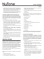
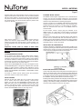
Locate the NWH300 or the NWH300C rough-ins. The rough-in
must be positioned so that the transformers are on the bottom of
therough-inasshowninthegurebelow.
If you are replacing the existing master only system with a
combination NM100 master and NC300 CD changer you will
have to cut the rough-in opening larger to accommodate the
larger rough-in. Prior to making the cutout check the stud
cavity for obstructions or items in the wall that may prevent
the transformers from tting in the wall. The NWH300 and
NWH300C transformers drop in from the bottom of the rough-in.
Pleaserefertothenextgureforrough-inplacement.
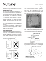
Connecttheexisting,dedicated120VAC/60Hzlinewithground
connection from the power panel to the rough-in as shown
below. The NM100 requires a dedicated power source to assure
no interference from other equipment caused by looped power
circuits. The ground is necessary for proper radio reception.
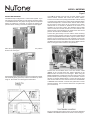
Place transformer enclosure from the inside of the wall housing
into the transformer enclosure opening at the bottom of the
rough-in as shown below. Do not run the 120VAC through the

MODEL NM100WH
Page 4
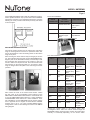
REPLACING THE ROOM STATIONS
The remote and door stations use the existing wire and station
rough-inmountingframesorboxes.Toreplacethestation,rst
remove the old station. Leave the existing remote or door station
rough-ins in place.
After removing the remote station verify the integrity of the wire
run. Then install the mounting plate from the NF300RWH frame.
Align the plate on the wall either vertically or horizontally so that
the screw holes line up with those on the rough-in or box. Use
a level to make sure the plate is level. There are several screw
hole locations on the mounting plate so it can attach to many
rough-in designs. Mount the plate to the wall using the screws
provided.
NM100
CONNECTION
NUTONE
IWA3 CABLE
WIRE FUNCTION
White Blue Stripe or
Outside Silver Wire
Intercom Mic
AudioInput&
Control
Red Center Wire Ground
Green Red Stripe or
Outside Copper
Wire
Speaker
Output/Monitor
Mic Input
Four-wire Installations
Connect the remote station to the existing wiring using
the diagrams above. Place the remote station through the
NF300RWH plastic mounting frame. Position the frame either
vertically or horizontally depending on the remote station
Three-wire Installations
Next connect the wires to the retrot remote station. Match
the wire colors to the corresponding screw locations on the
NRS103WH or NRS104WH remote stations. Please make sure
to use only NRS103WH remote stations in a 3-wire installation
and NRS104WH remote stations in a 4-wire installation. All 6-
wire installations use the NRS200WH remote stations. Please
refertoappendixAfora diagram of which NuTone and M&S
systems map to the 3, 4 or 6-wire (requires NM200 master)
congurations.RefertothefollowingtwochartsfortheNM100
wiring diagram:
FortheNWH300CMasterStationandCDcombinationrough-in,
haveaqualiedelectricianloopapowerwirefromtheNA300TA
transformer enclosure to the NA200TA transformer enclosure
following the same procedure described previously and shown
inthenextgure.
NM100 NUTONE 4 M&S4 WIRE
FUNCTION
White Blue Stripe
Wire
Silver
Outside Gray
Wire
Intercom Mic
Audio Input
Black Gray/Copper
Wire
Next Copper
Outside Gray
Wire
Intercom
Control
Red Gray/Silver
Wire
Next Copper
Outside Gray
Wire
Ground
Green Red Stripe
Wire
Outside
Copper
Outside Red
Stripe Wire
Speaker
Output/Monitor
Mic Input
NM100 M&S
MS4XSC
CABLE
NUTONE
NW4S
CABLE
WIRE
FUNCTION
White White Red Interom Mic
Audio Input
Black Black Black Intercom
Control
Red Red Orange Ground
Green Green Yellow Speaker
Output/Monitor
Mic Input

MODEL NM100WH
Page 5
INSTALLING THE NC300 CD CHANGER
Connect the audio cables to the audio jacks of the NC300 player as
showninthegurebelow.Afterconnectingtheaudiocablesand
maincable,connectthepowercordfromtheNA200TAtransformer
to the power connector on the NC300 CD changer. Please refer to
the installation manual packed with the NC300 CD changer.
Ensuring that nothing is between the CD player and the back of the
rough-in(includingcables),placetheNC300playerintothelower
opening of the frames including the NF200C or NF100C frames.
Use the screws provided to secure the unit in place.
replaced. Place the remote station into the rough-in ring and
align the frame with the remote station. Use the screws provided
with the remote station to screw the remote station and frame
into place. The holes in the remote station align with the holes in
the mounting plate. The remote station keeps the plastic frame
in place on the wall.
Note that the plastic frames are paintable. Please prime the
plastic rst and then apply standard room paint. The white
plastic may require two coats of paint to get full coverage. It is
recommended that you paint the frame prior to mounting it to
the wall.
Important: Please label all cables at both ends.
Incorrectly connecting cables to the master, remote
stations or door stations could result in system
damage.
OUTDOOR REMOTE STATIONS
Do not remove the existing outdoor remote station rough-in.
TheNuTone retrot system isdesigned to t intothe existing
enclosure. It is important to note that the outdoor remote stations
are weather resistant not water proof. These stations should not
belocatedinanareathatisindirectlineofwaterfromsprinklers,
rain or other devices such as power washers.
Please use the NF300PWH frame in outdoor and high sun areas.
The NF300PWH plastic is designed to withstand sun and resist
fading.Ifapatiorequiresasurfacemountapplication,usethe
NRKS200PWH. This is a surface mount box and cover that will
support the NPS200WH, NPS103WH or NPS104WH outdoor
remote stations.
To install an outdoor remote station follow the instructions
presented earlier for indoor remote stations.
DOOR STATIONS
Remove the old door station but do not remove the rough-in
box or surface mount box. When replacing a NuTone door
station you must use the NF300DWH mounting frame. The
M&SdoorstationsetsintheNF300DWHframeandthescrews
attach to the existing rough-in. Connect the door station with
the corresponding color wires. Screw the door station or door
station with NF300DWH frame into the rough-in box.
EXTERNAL MUSIC SOURCE
TheNM100retrotsystemsupportstheuseofexternalmusic
sources. You can use an existing connection or run a new wire
to support local source connection. To install a new local source
follow the steps detailed in the following paragraphs.
Choose a location for the IA30WH audio wall plate that will be
easily accessible to the sources that are to be connected to the
system(closetothereceiver,TVorDVDplayerforexample).
Note: the external source wire run to the NM100 must not
exceed 50 feet.
At this location, attach a single gang box included in the
IR30K rough-in to a wall stud at a center height of normal wall
outlets. Use a low voltage plaster ring in existing construction
installations.
Make sure the single gang box extends past the wall stud and
into the room so it will be ush with the sheetrock when it is
applied. Run the Red and Black shielded audio cables (included
in the IR30K) from the master unit location to the IA30WH audio
wall plate location. Connect the cables.
INSTALLING THE CHIME MODULE
Install the NA3003C or NA3008C optional chime module in the
rough-in by pressing the chime module over the 4 plastic standoffs
attachedtotherough-inasshowninthefollowinggure.Refer
to the instructions shipped with the chime module.

MODEL NM100WH
Page 6
Place the jumpers you just disconnected in the 4-wire position
showninthenextgure.
Suspend the master unit from the rough-in by looping the support
wire assembly (thick green wire) over the hook at the top of the
rough-in. Be careful not to damage the wall surface.
Plug in the modular chime plug to the 4 pin connector labeled as
CHIMEontheNM100masterunitasshowninthenextgure.
If the NM100 system has more than 9 remote stations, some
remote selector switches will control two remote stations.
Connect each Green wire (except patio/outdoor remote Green)
to a single green terminal on the master. Each numbered Green
terminal corresponds to a remote station selector switch. Note:
No more than 2 Green wires can be connected to any Green
terminal and not to exceed 15 speakers for the 4-wire or 13
speakers for the 3-wire system. This limitation does include
remote controls and volume controls but not door stations. The
station location can be marked on the inside of the door access
panel on the left side of the NM100 master.
Connect the green wire(s) from the outdoor remote station(s)
to the Patio green terminal. Connect the outdoor remote Black
wire(s) to the patio Black terminal. Note: Only two outdoor remote
stations can be connected to the patio terminals. Connect the
Red wire with the other Red wires to the Red terminal. Connect
the White wire with the other White wires to the White terminal.
Refertothegureshownbelowforwireplacement.
Connect the red and black wires of the door station cables
(NW4S) to the red and black door station terminals on the
NM100 master as shown in the next gure. When using the
NW4Sshieldedwire,insulatethebarewiresusingsomeofthe
jacket material to prevent shorting to the circuit board. Connect
this wire to terminal labeled shield. Connect all orange wires
from the door stations to the common terminal on the NA3003C
or NA3008C chime module. Connect each yellow wire to a note
sleection terminal. (Do not connect more than one yellow wire
per note terminal).
INSTALLING THE NM100
TheNM100shipsconguredfora3-wireretrotsystem.Ifyou
are replacing a 4-wire system you must change the jumper setup
on the NM100 master. The jumper change must be completed
before any cables are connected. To change the jumpers just
pullthemofftheexistingconnectionsshowninthenextgure.

MODEL NM100WH
Page 7
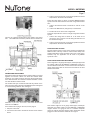
3. Connect a bare jumper wire (a 22 gauge speaker wire works
well) between the S3 and S4 terminals.
Follow the steps below to attach a separate AM/FM antenna
system with 300 Ohm FM twin lead and orange AM antenna
wire:
1. Connect the FM twin leads to terminal S1 and S2 on the
board
2. Connect the AM antenna (orange wire) to terminal S4
3. TerminalS3isnotusedinthisconguration
Follow the steps below to connect a single orange wire antenna
system:
1. Connect the orange wire to either S1 or S2. Note do not
connect the wire to both S1 and S2 doing this will short out
the FM antenna signal.
2. Connect a bare jumper wire (a 22 gauge speaker wire works
well) between the S3 and S4 terminals.
DOOR RELEASE OPTIONS
The door release option is a dry contact closure provided by the
NM100 master. This dry contact is rated 24 Volt/2 Amps. The
sample applications below represent some uses of this option.
However, only one application can be used in any NM100
system at a time.
DOOR OR GATE RELEASE MECHANISM
Runasinglelineof18gaugesolidcopper,twistedpairapproved
low voltage cable from the NWH300 or NWH300C rough-in to
the door release mechanism. Connect the two wires from the 18
gauge solid copper cable to the two wire terminals of the door
release mechanism.
Connect the optional NC300 player RCA cables and control
wire. See additional instructions packed with the NC300 CD
Runanothersingleline of18gaugesolidcopper,twistedpair
approved low voltage cable from the NWH300 or NWH300C
rough-in location to a gang box next to a 120VAC receptacle
where the remote door/gate release power transformer will be
plugged in. Label and secure cables at the rough-in.
changer.
CONNECTING THE ANTENNA
Separatetheintercomcablesfromtheantennaleads,ifgrouped
together the intercom cables can shield the antenna leads
resulting in poor radio reception. Keep the antenna leads away
from metal ductwork and aluminum backed insulation. These
can also shield the antenna leads.
The number and style of antenna leads will vary based on the
intercom system being replaced. The NM100 system is designed
tousetheexistingantenna.Seenextgure.
Follow the steps below to attach a NuTone 300 Ohm twin lead
antenna to the NM100.
Iftheantennahasaplugontheend,cuttheplugoff
1. Strip the 2 wire ends
2. Connect the wire ends to terminal S1 and S2 on the antenna
board

MODEL NM100WH
Page 8
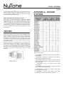
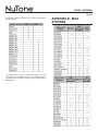
APPENDIX A - NUTONE
SYSTEMS
*Refer to frames below:
• NF100MWH – Replacing a master only system with an
NM100 master
• NF100CWH – Replacing a combination system with an
NM100 master and NC300 CD player
• NF200CWH – Replacing a master only system with an
NM100 master and NC300 CD player (requires hole in wall
to be made larger)
• NF300RWH – Used on all indoor remote station
replacements
•NF300PWH–Usedonalloutdoororhighsunareaush
mount remote station replacements
• NRKS200PWH – Used on all outdoor surface mount
remote station replacements
• NF300DWH – Used on older NuTone door station
replacements,notrequiredforM&Sreplacements
Afterallconnectionshavebeenmade,inserttheNM100power
plug into NA300TA transformer and secure the master to the
rough-inusingthe2screwsprovided.IfusingtheNF200CWH,
NF100CWHorNF100MWHframewithaNC300player,install
the master unit over the frame. Do not over tighten the screws
as the plastic may distort or crack. Install the speaker panel on
the master as shown.
Please be careful to only apply pressure on the speaker panel
at the corners and not in the middle. Check all functions by
following the guidelines in the Owners Manual shipped with
themasterunit.Ifanydifcultiesareencountered,recheckall
connections. If after reviewing these instructions you are unable
to resolve any problems, contact technical support at 1-888-
336-6151.
TESTING
The door release switch contacts are very versatile and can be
used with many AC/DC door or switch contacts. Be sure to use
thewireandpowersupplyortransformerspeciedbythedoor
or gate release product being used.
PANIC INTERFACE WITH SECURITY SYSTEM
Run a line of 18 gauge solid copper, twisted pair approved
low voltage cable from the NWH300 or NWH300C rough-in
location to the security control panel. Setup the security panel to
receive a normally open dry contact for panic operation. (Refer
to programming procedures accompanying the security panel).
Label and secure cables at the NWH300 or NWH300C rough-
in.HaveacertiedsecurityinstallerhooktheNM100uptothe
alarm system.

MODEL NM100WH
Page 9
APPENDIX B - M&S
SYSTEMS
*If existing system is loop or partially loop wired, it can only
be converted to the IM5000 system. If the existing system is
completelyhomerunwired,thesystemcanbeconvertedtoan
NM200 system.
The following NuTone systems map to either the IM-3303 or
IM-4406 systems:

MODEL NM100WH
Page 10

MODEL NM100WH
Page 11
Two Year Limited Warranty
WARRANTY OWNER: Broan-NuTone warrants to the original consumer purchaser of its products that such products will be free from defects in materials or workmanship for a period of
two (2) years from the date of original purchase. THERE ARE NO OTHER WARRANTIES, EXPRESS OR IMPLIED, INCLUDING, BUT NOT LIMITED TO, IMPLIED WARRANTIES OF
MERCHANTABILITY OR FITNESS FOR A PARTICULAR PURPOSE.
During this two year period, Broan-NuTone will, at its option, repair or replace, without charge, any product or part which is found to be defective under normal use and service. THIS
WARRANTY DOES NOT EXTEND TO FLUORESCENT LAMP STARTERS OR TUBES, FILTERS, DUCT, ROOF CAPS, WALL CAPS AND OTHER ACCESSORIES FOR DUCTING. This
warranty does not cover (a) normal maintenance and service or (b) any products or parts which have been subject to misuse, negligence, accident, improper maintenance or repair (other
than by Broan-NuTone), faulty installation or installation contrary to recommended installation instructions.
The duration of any implied warranty is limited to the two year period as specified for the express warranty. Some states do not allow limitation on how long an implied warranty lasts, so the
above limitation may not apply to you.
BROAN-NUTONE’S OBLIGATION TO REPAIR OR REPLACE, AT BROAN-NUTONE’S OPTION, SHALL BE THE PURCHASER’S SOLE AND EXCLUSIVE REMEDY UNDER THIS
WARRANTY. BROAN-NUTONE SHALL NOT BE LIABLE FOR INCIDENTAL, CONSEQUENTIAL OR SPECIAL DAMAGES ARISING OUT OF OR IN CONNECTION WITH PRODUCT
USE OR PERFORMANCE. Some states do not allow the exclusion or limitation of incidental or consequential damages, so the above limitation or exclusion may not apply to you. This war-
ranty gives you specific legal rights, and you may also have other rights, which vary from state to state. This warranty supersedes all prior warranties.
WARRANTY SERVICE: To qualify for warranty service, you must (a) notify Broan-NuTone at the address or telephone number below, (b) give the model number and part identi-
fication and (c) describe the nature of any defect in the product or part. At the time of requesting warranty service, you must present evidence of the original purchase date.
Date of Installation
Builder or Installer
Model No. and Product Description
IF YOU NEED ASSISTANCE OR SERVICE - CONTACT:
Broan-NuTone LLC Hartford, Wisconsin www.nutone.com 888-336-3948
Broan-NuTone Canada Mississauga, Ontario www.nutone.ca 877-896-1119 Rev. 08/2007
Garantie limitée de deux ans
GARANTIE DU PROPRIÉTAIRE: Broan-NuTone garantie à l’acheteur original de ses produits que ces derniers seront exmpts de tout défaut de matériaux et de fabrication pour une période de deux (2) ans à
compter de la date d’acha. AUCUNE AUTRE GARANTIE, IMPLICITE OU EXPRESSE, N’EST DONNÉE, Y COMPRIS, MAIS SANS S’Y LIMITER, GARANTIE DE MARCHANDIBILITÉ OU D’ADAPTATION
À UN USAGE PARTICULIER.
Pendant cette période de deux ans, Broan-NuTone procédera au remplacement ou à la réparation sans aucuns frais, mais à sa propre discrétion, de tout produit ou pièce jugé défectueux dans le cadre d’une
utilisation normale. CETTE GARANATIE NE VISE PAS LES DISPOSITIFS D’AMORCAGE NI LES TUBES DES LUMINAIRES FLUORESCENTS. Cette garantie ne couvre pas (a) l’entretien et le service courants
ni (b) les produits et les pièces ayant fait l’objet du’n usage abusif, de négligence, d’un accident, d’un entretien ou d’une réparation non appropriée (par du personnel non autorisé par Broan-NuTone) d’une mauvaise
installation ou d’une installation non conforme aux directives d’installation fournies.
La durée de toute garantie implicite est limitée à la période de deux ans précisée pour la garantie expresse. Certains états ne reconnaissent pas les restrictions relatives à la durée des garanties implicites; il se
pourrait donc que cette restriction ne s’applique pas dans votre cas.
LE REMPLACEMENT OU LA RÉPARATION PAR BROAN-NUTONE, À SA PROPRE DISCRÉTION, DE TOUT PRODUIT OU PIÈCE DÉFECTUEUX CONSTITUE LE SEUL REMÈDE DE L’ACHETEUR
EN VERTU DE CETTE GARANTIE. BROAN-NUTONE NE PEUT ÊTRE TENUE RESPONSABLE DES DOMMAGES INDIRECTS, CONSÉCUTIFS OU SPÉCIAUX ATTRIBUABLES À UTILISATION OU AU
RENDEMENT DU PRODUIT. Certains états ne reconnaissent pas les restrictions ni les exclusions relatives aux dommages indirects, consécutifs ou spéciaux; il se pourrait donc que cette restriction ne s’applique
pas dans votre cas. La présente garantie vous accorde des droits spécifiques, mais vous pourriez aussi avoir d’autres droits en fonction de l’état dans lequel vous résidez. Cette garantie remplace toute autre
garantie donnée précédement.
SERVICE SOUS GRANTIE: Pour être admissible au service sous garantie, vous devez (a) aviser Broan-NuTone, à l’adresse ou au numéro de téléphone ci-dessous, (b) fournir le numéro du modèle et
la description de la pièce et (c) décrire la nature défaut de la pièce ou du produit. Au moment de la demande de service sous garantie, vous devez fournir une preuve de la date d’achat originale.
Date d’installation
Entrepeneur ou installateur
N° de modèle et description du produit
POUR OBTENIR DE L’ASSITANCE OU DU SERVICE - CONTACTEZ:
Broan-NuTone LLC Hartford, Wisconsin www.nutone.com 888-336-3948
Broan-NuTone Canada Mississauga, Ontario www.nutone.ca 877-896-1119 Rev. 08/2007
Garantia limitada de dos años
GARANTÍA DEL PROPIETARIO: Broan-NuTone garantiza al comprador consumidor original de sus productos, por el período de dos (2) años desde la fecha original de compra, que tales productos están libres de
defectos en material y mano de obra. NO HAY OTRAS GRANTÍAS, EXPRESADOS O SOBREENTENDIDAS, INCLUYENDO, PERO NO LIMITADAS A, GRANTÍAS NO EXPRESADAS DE MERCHNTIBILIDAD
O ADAPTABLES A UN PROPÓSITO EN PARTICULAR.
Durante este período de dos años, Broan-NuTone reparará o reemplazará a su opción y sin costo, cualquier producto o parte que se encuentre defectuoso bajo condiciones normales de uso y servicio. ESTA
GARANTÍA NO CUBRE A LOS ARRANCADORES PARA LÁMPARAS FLUORESCENTES O A LOS TUBOS FLUORESCENTES, FILTROS, DUCTOS, TAPAS DE TECHO, TAPAS DE PARED Y OTROS
ACCESORIOS PARA CANALIZACIÓN. Esta granatía no cubre (a) Mantenimiento y servicios normales (b) Productos o partes sujetos al mal uso, negligencia, accidente, mantenimiento inadecuado o reparaciones
(port otros ajenos a Broan-NuTone), instalación defectusoa o a una instalación contraria a las instrucciones de instalación recomendadas.
La duración de cualquier garantia no expresada está limitada a un periodo de dos años según se especifica en la garantia expresada. Algunos estados no permiten limitación en cuanto a la duración de una grantia
no expresada, por lo que la limitación arriba indicada puede que no se apliqué a Ud.
LA OBLIGACIÓN DE BROAN-NUTONE DE REPARAR O REEMPLAZAR A SU OPCIÓN, SERÁ EL ÚNICO Y EXCLUSIVO RECURSO QUE TENDRÁ EL COMPRADOR BAJO ESTA GARANTÍA. BROAN-
NUTONE NO SERÁ RESPONSABLE POR DAÑOS INCIDENTALES, CONSECUENTES O ESPECIALES QUE RESULTEN A CONSECUENCIA O SEAN INDEPENDIENTE DEL USO O DESEMPEÑO DEL
PRODUCTO. Algunos estados no permiten la exclusión o limitación de daños incidentals o consecuentes, de modo que la limitación o exclusión arriba indicada pueda que no se aplique a Ud. Esta garantia le
proporciona derechos legales especificos, y Ud.puede tener otros derechos, los cuales varían de estado a estado. Esta garantias reemplaza a todas las garantías anteriores..
SERVICO DE GARANTÍA: Para tener derecho al servicio de garantía, Ud. debe (a) Notificar a Broan-NuTone a la dirección o el número de teléfono abajo, (b) indicar el número de modelo y la identifación
de la party y (c) describir la naturaleza de cualquier defecto en la producto o parte. Al momento de solicitor el servicio por la garantía, Ud. debe presentar la evidencia de la fecha original de compra.
Fecha de la instalación
Constructor o instalador
Número de modelo y descripción del producto
SI NECESITA ASISTENCIA O SERIVIVIO - CONTACTO:
Broan-NuTone LLC Hartford, Wisconsin www.nutone.com 888-336-3948
Broan-NuTone Canada Mississauga, Ontario www.nutone.ca 877-896-1119 Rev. 08/2007
-
 1
1
-
 2
2
-
 3
3
-
 4
4
-
 5
5
-
 6
6
-
 7
7
-
 8
8
-
 9
9
-
 10
10
-
 11
11


NuTone NM100WH Instructions Manual
- Catégorie
- Systèmes d'interphone de porte
- Taper
- Instructions Manual
dans d''autres langues
- English: NuTone NM100WH
Documents connexes
-
NuTone NM100WH Manuel utilisateur
-
NuTone NM200AL Manuel utilisateur
-
NuTone NM300 Series Manuel utilisateur
-
-
NuTone NC300WH Manuel utilisateur
-
-
-
-