
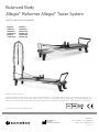
The Balanced Body
Allegro® Reformer Allegro® Tower System
THIS IS A MEDICAL DEVICE
Statement of Intended Use
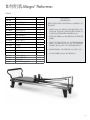
The Allegro® Reformer Allegro® Tower System device is intended by the manufacturer to be used by people for the purposes of physiotherapy, rehabilitation, the
prevention, treatment and relief of injuries, supportive, functional therapy for a disability or for general strengthening and improving the mobility of the human body.
Should injury occur during usage please report to the manufacturer and competent authority of the Member State in which the user and/or patient is established.
For printed instructions contact Balanced Body.
Balanced Body, Inc
Sacramento, CA
001-916-388-2838
EC
EMERGO EUROPE
Molenstraat 15
2513 BH, The Hague
The Netherlands
REP
Contact Us
1-800-PILATES | +1-916-388-2838
pilates.com | info@pilates.com
10896 | 2021-06
Balanced Body, Inc.
5909 88th St,
Sacramento, CA 95828 USA
Art.Nr. 1492978
Englisch: ab Seite 1
Spanisch: ab Seite 50
Italienisch: ab Seite 103
Französisch: ab Seite 156
Deutsch: ab Seite 206
Chinesisch: ab Seite 259


IMPORTANT:
This manual is intended for medical and fitness professionals, or persons with experience in the use of this equipment. If there is a
question regarding appropriateness of a particular movement, please consult a licensed health professional.
Safety Note: Warning – The Allegro contains flammable materials, please keep away from direct heat/exposed flame.
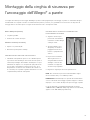
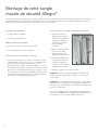
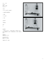
INTRODUCTION
The Allegro system is designed to combine the functions of the Allegro Reformer and the Tower or Half Trapeze into one compact
and portable piece of Pilates equipment . The Allegro Tower can be installed on any Allegro and allows additional exercises to be
performed without increasing the footprint of the apparatus. The following manual outlines the features of the Allegro Reformer and
Allegro Tower as well as suggested exercises.
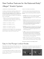
Balanced Body is the world’s leading resource for Pilates equipment, education and information. The Balanced Body Studio Reformer
is the biggest selling Reformer on the planet, and its Allegro Reformer now sets the Pilates standard for health and fitness clubs
around the globe.
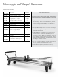
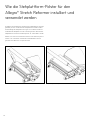
SET-UP TIPS (READ FIRST)
»If you are setting up an Allegro Reformer with no Leg Kit, proceed with these Reformer instructions beginning
on page 9.
»If you are setting up an Allegro Reformer with with Leg Kit, install the legs first, see page 13, then set up the
Reformer beginning on page 9.
»If you are setting up an Allegro Reformer with a Tower System but no Leg Kit follow these instructions for the
Reformer on page 9 and then continue to the Tower System section on page 17.
»If you are setting up an Allegro Reformer with a Tower System and Leg Kit, install the Leg Kit first, see page 13,
followed by the Tower on page 17, then the Reformer on page 9. To save time, do not re-install the head end
rail cover plates as described at the end of the Leg Kit install instructions. You will need them off to install the
Tower.
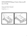
»If you are setting up an Allegro Stretch Reformer, please see page 22. For Allegro Stretch footbar features
please see page 25.
1

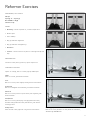
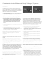
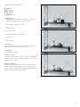
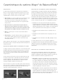
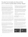
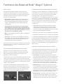
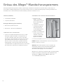
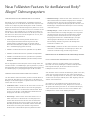
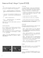
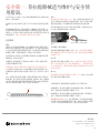
Features of the Balanced Body® Allegro® System
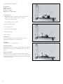
HEADREST
The headrest is used to optimally support the user’s head, neck
and shoulders while lying in a supine position. The Allegro has
three headrest positions that are adjusted by a support block
underneath the headrest:
»Low (flat) – The support block is folded toward the top of the
headrest. Used for clients with relatively flat thoracic spines
and shallow ribcages for leg and footwork, and for any supine
exercise.
»Safety Note: The flat headrest position is used for all
clients in exercises where they will be rolling up on to their
shoulders. A flat headrest will keep the client from over
flexing the cervical spine and injuring the neck.
»Medium – The support block rests on the notch in the middle
of the support block.
»High (up) – The bottom of the support block rests on the
carriage. Used for clients with a forward head or a deep rib
cage to facilitate correct alignment.
Instructor Note: A towel can also be used in addition to or instead
of the headrest to adjust the height of the head.
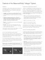
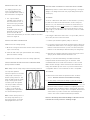
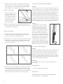
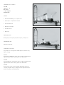
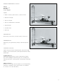
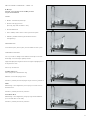
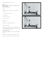
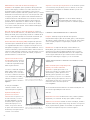
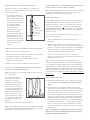
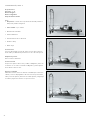
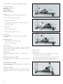
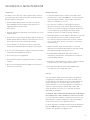
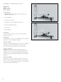
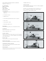
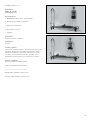
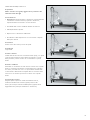
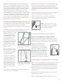
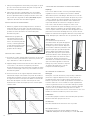
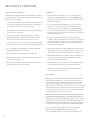
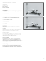
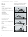
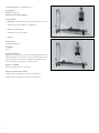
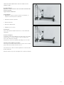
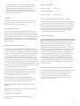
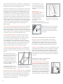
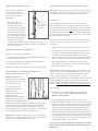
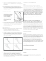
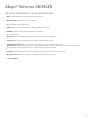
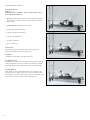
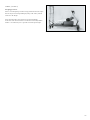
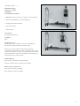
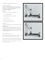
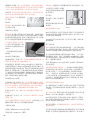
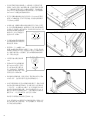
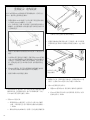
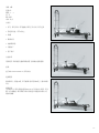
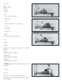
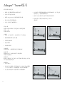
EASY TO USE PLUNGER LOCKOUT KNOBS
Balanced Body’s Allegro® Reformer, and Clinical Reformer® and
Studio Reformer® with Infinity footbars come with plunger lockout
knobs that make adjusting and moving the Reformer footbar
along the frame much easier.
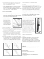
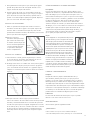
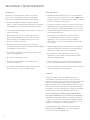
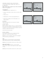
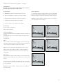
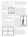
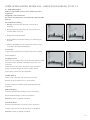
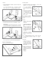
To use, pull the plunger knob straight out so that the recessed
cross-pin comes out of the slots as shown in Figure A. Then turn
the knob so that the cross-pin rests on the bolt head as shown in
Figure B. Repeat on other side.
With the knobs in the “locked out” position, reposition the footbar
along the frame of your Reformer as desired. Then turn the
knobs so that the cross-pin is once again recessed, firmly locking
the footbar into its new position.
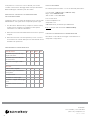
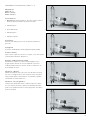
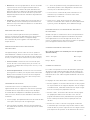
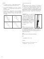
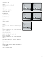
HORIZONTAL FOOTBAR ADJUSTMENTS
The Allegro is equipped with an adjustable footbar that can be
moved in order to accomodate users of different heights. To
move the footbar, pull the round black knobs on the bottom of
the footbar out and turn 90 degrees to lock out. Slide the footbar
forward or backward until it is lined up with the desired hole on
the track. Turn knob until the pin engages into a hole. Make sure
the pin is fully engaged.
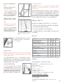
»Hole 1 is closest to the footbar end of the Reformer and
creates the longest distance between the shoulder rests
and the footbar. It is used for taller users (over 6’ or where
decreased knee and hip flexion is desired.
»Hole 2 is for users between 5’9” and 6’
»Hole 3 is for users between 5’5” and 5’9”
»Hole 4 is for users between 4’10” and 5’5”
The heights given here are suggestions. The footbar adjustment
should allow the user to have slightly less than 90° of hip flexion
when the carriage is all the way in for leg and footwork.
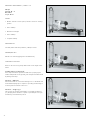
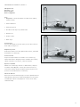
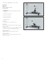
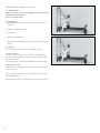
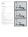
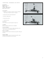
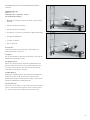
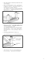
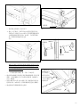
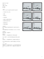
VERTICAL FOOTBAR ADJUSTMENTS
To adjust the footbar vertically, squeeze the handle at the bottom
of the footbar until the pin disengages from the plate. Move the
footbar to the desired height and release the pin into the hole.
»High Bar – Move the pin into the highest hole and release the
handle. The high bar position shortens the space between
the shoulder rests and the footbar. This position is used for
foot and legwork with shorter users, and with users who have
difficulty keeping their back placement due to increased
lumbar lordosis or a tight back.
»Middle Bar – Place the pin in the 2nd hole from the top on the
plate. The middle bar position lengthens the space between
the shoulder rests and the footbar. This decreases the flexion
of the knees in foot and legwork and places the torso in a
neutral standing position.
»Low Bar – Place the pin in the 3rd hole on the plate. The low
bar position increases the space between the shoulder rests
and the footbar to its maximum length. This decreases the
flexion of the knees in foot and legwork, decreases the flexion
of the torso and hips in elephant and can be useful for taller
or more flexible users.
»No Bar – Place the pin in the lowest hole on the plate. This
position is used to move the bar out of the way for standing
exercises and for exercises where the user is lying on the box.
Figure A Figure B
2

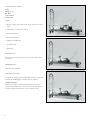
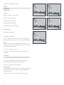
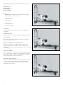
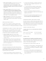
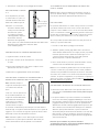
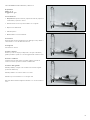
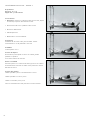
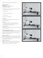
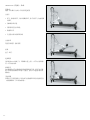
SPRING ADJUSTMENTS
Springs are used to adjust the resistance for different exercises.
There are at least 30 different resistance settings that can be
used on the Allegro. Suggested weight ranges are noted under
each exercise.
CHANGING THE SPRING ATTACHMENT POINTS
On the Allegro, spring tension is adjusted by attaching different
combinations of springs to the pegs under the standing platform.
To safely adjust the springs make sure the carriage is in the
home position.
»Normal position – Place the spring on the peg directly in
front of it. In this position the springs are under no tension to
start with. This is designated as “B” position. There are five B
positions.
»Pre-loaded position – Place the spring on the peg just to
the left of right, under the standing platform. This position
will put the springs under a small amount of tension and will
increase the resistance of the springs. This is designated as
“A” position. There are six A positions.
SPRING WEIGHT
Spring resistance is indicated by the approximate number of
springs suggested for a specific exercise. The spring weight
indicated is a recommended starting position. Individual
adjustments can be made depending on user needs and the
exercise.
»1 spring (light): Primarily used for arm work or where the
carriage is providing light support
»2 springs (light to moderate): Used for arm work, legwork and
exercises where the carriage is providing support to the user.
»2 – 4 springs (moderate to heavy): Primarily used for legwork
and to increase resistance for stronger users.
»All springs: Used to maximize resistance or to stabilize the
carriage for the short box abdominal series.
»No springs: Used for added difficulty in exercises where the
user needs to control the carriage (kneeling abdominals,
elephant, long stretch series).
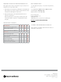
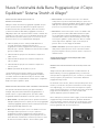
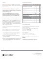
SPRING PROGRESSIONS FOR THE ALLEGRO
Please note that these spring combinations represent the usual
progression for a standard new machine and may vary slightly
depending on the age and specific strength of your springs. The
best way to find the optimal progressions for your machine is to
test it yourself.
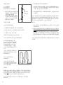
SPRING COLOR-CODING
These color codes are standard for Balanced Body Machines
Yellow – Very light Blue – Light
Red – Medium Green – Heavy
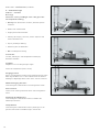
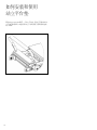
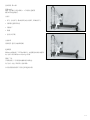
ROPES AND LOOPS
Ropes are adjusted according to specific exercise demands and
user size. To minimize rope adjustments, double loop straps allow
the user to grip the ropes at two different lengths without having
to adjust them.
The rope adjustments used in the manual are:
»Regular loops: Resistance of loop or handle is somewhat taut
on shoulder rests. With the double loop straps, the user will
hold the longer loop. Standard for most exercises.
»Short loops: Resistance of loop or handle is somewhat taut
on the black pegs pegs. With double loop handles the user
holds the smaller loop. Used for rowing and some arm work
exercises.
»Very short loops: Loop or handle is approximately 5 inches
shorter than the headrest. Used for kneeling arm work facing
the straps such as chest expansion or thigh stretch.
»Long loops: Loop or handle is longer than shoulder rest by a
length of one cotton loop. Used for long spine stretch or for
feet in the straps for users with tighter hamstrings.
3

RISERS
Risers can be adjusted by loosening the knob that holds the
pulley in the slot on the Tower and moving the pulley up or down.
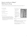
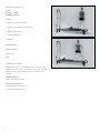
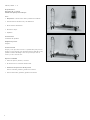
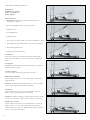
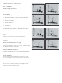
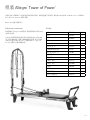
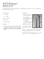
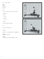
THE ALLEGRO TOWER
The Allegro Tower consists of a metal frame that attaches to
the head of the Allegro Reformer. Eyebolts in the frame provide
attachment points for the springs. Loops, handles or a wooden
Roll-down Bar can be attached to the springs creating a wide
variety of exercises. The Allegro Tower also has a Push-through
Bar.
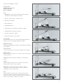
SPRING ATTACHMENT POINTS
The Allegro Tower has 24 spring attachment points creating
a variety of possible exercises and a limitless amount of
adjustability. Each upright has 5 eyebolts on the front and 5 on
the back allowing users to perform exercises from either side
of the Tower. Two eyebolts are attached to the Allegro frame to
create a low position, two eyebolts are attached to the sides of
the arch of the Tower and one is attached at the highest point
in the center. This single eyebolt is to hold the security strap
in position. Do NO attach springs to this eyebolt. Common
spring attachment points are listed below and in each exercise
description.
In order to adjust the tension of the springs for a particular client,
move the attachment point further away from the client to make
the spring heavier, move it closer to the client to make it lighter.
Low: Springs are attached from eyebolts at the bottom of the
Allegro frame. These springs are used to hold the Push-through
Bar in position.
Middle: Springs are attached to the 3rd eye hook from the
bottom.
High: Springs are attached to the high points on either side of
the arch at the top of the Tower.
ALLEGRO TOWER SPRINGS
The Allegro Tower comes with 4 sets of springs as follows:
2 Sets - Short springs
Yellow – Very light Blue – Light
2 sets - Long springs
Yellow – Very light Purple – Medium
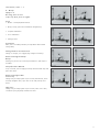
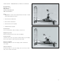
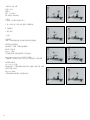
PUSH-THROUGH BAR ADJUSTMENTS
The Push-through Bar has two possible pivot points on the Tower
frame. To adjust the Push-through Bar, push the button on the
top of the T-pin in order to free the pin. Pull the pins out of the
uprights, move the bar to the appropriate hole and re-insert the
pins. Always return the Push-through Bar to a safe height if it has
been moved.
SAFETY NOTE:
It is very important that the instructor be present and spotting
the client whenever the Push-through Bar is in use. It is very
important that the pivot point be high enough to clear the users
head when they are lying under it. If a client has an especially
large head, excessive thoracic kyphosis or a large nose, the bar
can hit them when they are doing exercises. The Push-through
Bar should never be adjusted low enough to hit a client who is
lying under it. The safety strap must always be used when the
Push-through Bar is sprung from below. The safety strap must be
adjusted so that the angle of the Push-through Bar, when viewed
from the side, is no lower than the four or eight o’clock position
and will not hit the client should their feet slip off the bar.
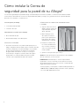
UPHOLSTERY CLEANING AND DISINFECTING.
You can extend the life of your upholstery by keeping it clean and
free of dirt, oil and perspiration. After each use, wipe down the
upholstery with a solution of mild soap and water. Then wipe it
down with clean water and dry with a rag.
4

Contact Us
1-800-PILATES | +1-916-388-2838
pilates.com | info@pilates.com
215-000 | 06.24.21
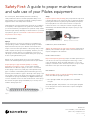
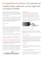
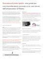
Safety First: A guide to proper maintenance
and safe use of your Pilates equipment.
For over 35 years, Balanced Body has been introducing
safety-related innovations to Pilates equipment. Many of our
improvements are now industry standards, resulting in Pilates
equipment that’s safer today than ever before.
Safety depends on proper maintenance and safe use, in addition
to the quality of the equipment. This guide was created to help
you use and maintain your equipment for optimum safety. Please
read it through carefully and keep for future reference. If you have
any questions, give us a call. Failure to follow these instructions
may result in serious injury.
ALL EQUIPMENT
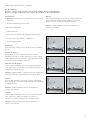
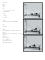
Springs
Spring inspections are critical to maintain your equipment in
safe operating condition. All Balanced Body springs should be
replaced at least every two years. Certain environments and
usages can shorten the expected life of the springs and you may
need to replace the springs more frequently. Therefore, it is very
important to inspect springs on a regular basis since worn or
old springs lose resilience and may break during use. Injury may
result if a spring breaks during use.
During use, do not allow springs to recoil in an uncontrolled
manner. This will damage the spring and shorten its expected life.
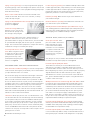
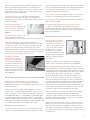
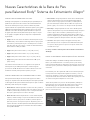
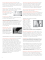
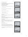
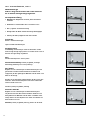
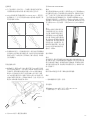
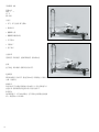
Inspect springs for gaps and kinks (weekly or monthly,
depending on frequency of use). Look for gaps and kinks
between the coils when the spring is at rest. It is not unusual
for the spring to have a very small gap on the tapered end (a
gap is sometimes created during the manufacturing process).
However, there should be no gaps in the body of the spring. If you
see any gaps or kinks in the body of the spring, discontinue use
and replace the springs immediately. See Figure 1. Additionally,
corrosion anywhere on the coils will shorten the life of the spring.
Discontinue using the spring immediately if you see any rust or
oxidation during inspection.
Kink
Figure 1
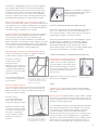
Snaps
Inspect snaps for wear (monthly). First, verify that the snap hook
is working properly. If the snap hook does not retract and return
properly, discontinue using the spring immediately and replace
the snap. Eyebolts can cause excessive wear on snap hooks.
If the hook shows a lot of wear, discontinue using the spring
immediately and call Balanced Body to replace spring or snap.
See Figure 2.
Figure 2: Good snap: no wear on hook. Bad snap: excessive wear on hook.
EYEBOLTS, NUTS AND BOLTS
Tighten all equipment bolts and screws (monthly). Verify that all
eyebolts, nuts and bolts are tight. See the section titled “How to
inspect and tighten nuts and bolts.”
ROPES AND STRAPS
Rope and strap wear (quarterly). Ropes should be replaced if you
can see the core of the rope through the outer lining, or if the
ropes are fl attened. Straps should be replaced as soon as any
fraying is noticed. Be sure to check the sections of rope or straps
that attach to the clips and run through the pulleys.
REFORMERS
Check springbar hooks or eyebolts (quarterly). Balanced Body
makes two different springbar systems:
»Revo Springbar. Make sure springbar hooks and handle
are tight.
Standard Springbar. Verify that the nuts securing the springbar
hooks are tight. See section titled “How to inspect and tighten
nuts and bolts.”
5

2
Spring rotation (quarterly). You can prolong Reformer spring life
by rotating springs of the same weight each quarter. Unhook and
move to another position on the springbar. Rotating springs helps
them wear more evenly.
Risers on the outside. Wood risers must be installed on the
outside of the frame. Risers can loosen over time, so always
make sure they are tight.
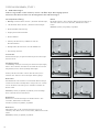
Springs hooked downward under carriage. Make sure springs are
hooked in a downward
position. See Figure 3.
Secure the carriage. When your
Reformer is not in use, be sure
that at least two springs secure
the carriage to the springbar.
Default settings. Many users have a “default setting” for
Reformers. At the end of a session, the user connects a
prescribed number of springs in neutral tension, sets the footbar
at a pre-determined height, and sets the ropes at a specifi ed
length. This ensures that the equipment is ready for the next use,
and that the carriage is secured by the springs.
Footstrap under tension in box
work. When using the box and
footstrap, be sure the footstrap
is under tension (with snaps
pulling from the top of the
eyebolt) before beginning the
exercise. See Figure 4.
REFORMER WHEEL AND TRACK MAINTENANCE
Clean the tracks and wheels (weekly). For smooth carriage travel
and to maintain the longevity of the wheels, we recommend that
you wipe down the tracks once a week.
Disconnect the springs and clean the entire length of the tracks
with a soft cloth and Balanced Body Cleaner, mild soap with
water or a mild commercial cleaner such as, Fantastik® or 409®.
Do not use abrasive cleansers or pads, as they can damage the
anodizing on the rails. To clean the wheels, hold the cloth against
the wheels while you move the carriage. If you feel a bump in
the ride, dirt has adhered to the surface of the rails or wheels.
Clean hair and debris out of the rails. Hair can wrap around the
wheel axles and eventually build up and cause wheel failure. Use
tweezers to remove hair from the wheels.
Lubrication. Never spray silicone near or inside the wheels – this
can wash the lubricant out of the bearings and ruin the bearings.
You can purchase dry silicone at most hardware and auto parts
stores. Pulleys sometimes require lubrication to stop a squeak.
Direct a very quick spray of dry silicone or Tefl on spray into the
pulley. “Dry” silicone does not have an oil base. Oil-based (“wet”)
silicone and WD40 should not be used as they attract dirt. Be
careful not to over spray. You may want to remove ropes to avoid
getting silicone on them.
Do not lubricate the Allegro 2 rails.
Footbar supports (quarterly). For all Balanced Body footbars with
footbar support brackets, verify that the pivot screw attaching the
footbar support bracket to footbar is tight, but not so tight that it
prevents the support from rotating freely. For Legacy Reformers,
tighten the pivot bolt to secure footbar support.
Headrest (monthly). Make sure the hinge screws and bolts on
your headrest are tight.
Under the Reformer (monthly). Move Reformers and make sure
you clean the fl oor space underneath.
Standing Platform Footbar Bumpers (wood Reformers only). If
your standing platform footbar bumpers (the small plastic pieces
that protect the standing platform from the footbar) are broken
or damaged, please call Balanced Body to replace.
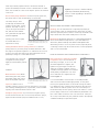
TRAPEZE TABLE (CADILLAC) & TOWERS
Cotter pins removed. These
pins are located in the vertical
tubes that align the canopy
to the frame and should be
removed as soon as installation
is complete. Unremoved cotter
pins can tear clothing and
lacerate the skin. Use pliers to
remove the pins.
Save the pins in case you need to disassemble and reassemble
the table for transportation purposes. See Figure 5.
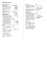
Push-Through Bar (PTB) with Sliders.
The PTB moves vertically to accommodate different users
and exercises. The sliders on the tubes allow for this vertical
movement. Make sure these sliders are clean and easy to move.
Before beginning any exercise, ensure that the sliders are properly
aligned with the PTB holes and locked into position. Apply a
downward force to ensure. If you notice wear on the slider knob
pins, please call Balanced Body to replace. Using the PTB in this
condition could cause injury.
Weekly maintentance for Push-Through Bars with Sliders. Check
to ensure the pins in the plunger knobs protrude and lock into
the vertical tubes. Pull both knobs out and move the sliders to
a different position. Release the knobs before the next hole and
continue to slide the system into position. Once over a hole the
pin of the knob will automatically drop into the opening. Once
each slider is in a new position apply a downward force on the
PTB. The pins of the sliders should not come out of the holes. If
the pins do not stay in the tube holes, the pull knobs need to be
replaced. Call Balanced Body for replacement parts.
Push-Through Bar (PTB) with T-pin setting.For bottom sprung
exercises, if your client’s head is below the PTB, use the T-pin setting
in addition to the safety strap or chain. Spotting your client is highly
recommended. This is important for safety.
Push-Through Bar (PTB) control. Make sure you have enough
room around the trap table to safely use the PTB without fear of
hitting other people. The PTB can be dangerous if not properly
Figure 3: Springs hooked downward
Figure 4: Foot strap under tension
Figure 5: Cotter pin before and after
removal from Trap Table.
6

3
used. Only trained, experienced users should use the PTB. A
spotter should always maintain control of the bar with one hand.
If the user should lose control of the bar, the spotter can maintain
control of it.
Correct safety strap attachment. For bottom-sprung exercises,
the safety strap or chain should always secure the bar.
The safety strap or chain
should wrap around the PTB
and the canopy frame, not the
eyebolts. The strap or chain is
only as strong as the weakest
link, and the frame and bar
are a great deal stronger than
eyebolts. Figure 6.
Spotting your client is highly
recommended. This is
important for safety.
Setting the PTB for bottom-sprung exercises. For bottom-
sprung exercises, the safety strap should be attached so that
the angle of the push-through bar is no lower than the 4 o’clock
position. This limits the range of the bar and prevents it from
potentially coming into contact with the user.
Using the 4th side on the PTB
along with the safety strap is
highly recommended to prevent
injury.
CHAIRS
Dismount with control. When
dismounting the chair, release
the pedals slowly, with control.
Don’t let the pedal snap back.
Spot users. When a user is
standing, sitting or lying on top of the chair, there is increased
risk of falling. Standing exercises, in particular, can be unstable.
Spotting users will make these exercises safer.
Hourglass spring mounts. If your chair has hourglass spring
mounts and the mounts do not successfully retain the springs,
replace the fi ber washers (they are reddish-brown in color).
Figure 8. If your chair is a Balanced Body
Split-step Pedal Chair (Combo Chair),
please consider upgrading to the Cactus
Springtree).
UPHOLSTERY CLEANING & MAINTENANCE
Cleaning. You can extend the life of upholstery by keeping it
clean and free of dirt, oil and perspiration. After each use, wipe
down the upholstery with a solution of mild soap and water. Then
wipe it down with clean water and dry with a soft towel.
Disinfecting. Equipment upholstery is coated with BeautyGard®,
which offers antibacterial protection. If you want additional
disinfection, Balanced Body offers Balanced Body CleanTM
disinfecting solution. Use of any other solution (especially those
containing essential oils) will shorten the life of some equipment
and is not recommended.
HOW TO INSPECT AND TIGHTEN NUTS AND BOLTS.
Use your fi ngers to check nuts and bolts
for tightness. If you can turn the nut or
bolt with your fi ngers, it’s too loose and
should be tightened. To tighten, fi rst
tighten using your fi ngers. Rotate nuts
and bolts clockwise to tighten. Insert a
screwdriver through eyebolts to hold them
steady while you tighten the nuts. Then
use a small wrench to tighten the nuts
further. Figure 9.
It is recommended to check the pins on the PTB protrude
and lock into the vertical tubes appropriately. To verify their
function, fi rst pull both knobs out and start moving the sliders
to a different position. Release the knobs before the next hole
and continue to slide the system. Once over a hole the pin of
the knob will drop into the opening. Once each slider is in a new
position apply a down force on the PTB directly downwards. The
pins of the sliders should not come out of the holes. If the pins
do not stay in the tube holes, the pull knobs need to be replaced;
call Balanced Body for replacement parts.
Figure 6: Safety strap holding the
push-through bar at 4 o’clock. The strap is
secured to the PTB and canopy frame, not
the eyebolts.
Figure 9: Use two fi ngers to
tighten bolts
Figure 7: Safety strap holding the
push-through bar at 4 o’clock. The strap is
secured to the PTB and canopy frame, not
the eyebolts.
Figure 8: Fiber washer
7

Contact Us
1-800-PILATES | +1-916-388-2838
pilates.com | info@pilates.com
215-000 | 06.24.21
EQUIPMENT INSPECTION AND MAINTENANCE LOG
We suggest that you keep a maintenance log for each piece of
equipment. The log should include:
1. A description of the machine including the serial number, the
date and place of purchase, and the manufacturer. All of this
information should appear on the invoice.
2. Date and description of all required maintenance and
inspections performed.
Date and description of each repair, including name and
contact information for person or company performing
the repair.
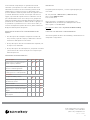
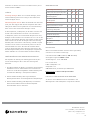
MAINTENANCE SCHEDULE
All Equipment Day Wk. Mo. Qtr.
Inspect springs for gaps & kinks
Inspect snaps for wear
Inspect nuts & bolts for tightness
Reformers
Clean wheels and tracks
Inspect springbar hooks/eyebolts
Rotate springs
Inspect ropes/straps
Inspect footbar supports
Inspect One-Step springbars
REPLACEMENT PARTS
To order replacement parts, or if you have any questions,
please call:
U.S. and Canada: 1-800-PILATES (1-800-745-2837)
United Kingdom: 0800 014 8207
Other locations: +1 916-388-2838
Fax: 916-379-9277
Email: in[email protected]
www.pilates.com
5909 88th Street, Sacramento, CA 95828 USA
Click here for Balanced Body Patent Data.
ASSEMBLY AND MAINTENANCE PODCASTS
View our library of assembly and maintenance videos at
www.pilates.com\podcasts.
8
Click here for Balanced Body Patent Data.

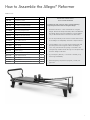
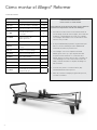
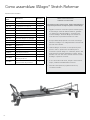
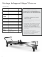
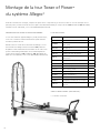
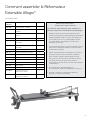
How to Assemble the Allegro® Reformer
PARTS LIST
Part number Description Qty
950-002 Complete footbar 1
950-020 Shoulder bolts and washers 1 kit
950-228 Shoulder rest with brackets 1 pair
616-400 Locking shoulder post 2
GEN8000 Twist lock plunger knobs 2
210-070 Soft Touch Ropes 1 pair
210-064 Double loops (Soft Touch) 1 pair
950-225 Allegro riser with pulley 2
GEN9050 5/16” Allen wrench 1
ALL0060 Allegro wrench 1
SPR9070 Red spring 3
SPR9071 Blue spring 1
SPR9241 Yellow spring 1
UPH7040 Foam Pad for Standing Platform 1
GEN9282 5/32” Allen wrench 1
GEN9472 1/4”-20 Button head screw 2
GEN9054 Split washer 2
618-008 Transport bracket preinstalled with wheel 2
IMPORTANT PRECAUTIONS:
PLEASE READ WARNING
To reduce the risk of serious injury, read the following
important precautions before using the Allegro.
»Read all instructions in this manual before using the
Allegro. Review the Setup and Safety video included with
the Allegro before using the equipment. Use the Allegro
only as described in these instructions and the video.
»It is the responsibility of the owner to ensure that all users
of the Allegro are adequately informed of all precautions.
»Use the Allegro only on a level surface. Keep hands and
feet away from all moving parts. When the Allegro is
not in use, leave at least two springs connected to the
carriage. Keep children under the age of 12 and pets away
from the Allegro at all times.
»If you feel pain, dizziness, or shortness of breath, stop
exercising immediately.
»Before beginning any exercise program, consult your
physician.
9

10
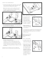
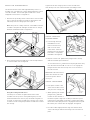
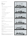
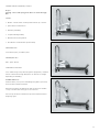
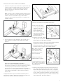
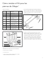
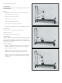
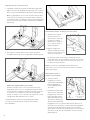
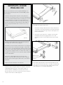
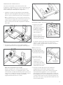
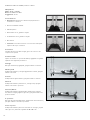
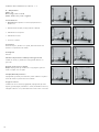
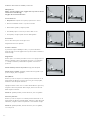
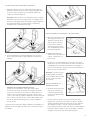
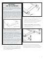
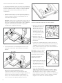
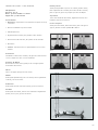
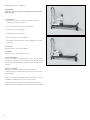
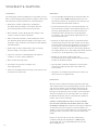
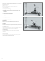
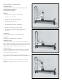
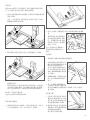
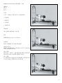
INSTALL THE SHOULDER RESTS
1. Note the two protruding studs on the bottom of the shoulder
rests. Lower the shoulder rest studs into the keyholes and
slide away from the carriage pad. See Figure A.
Note: The shoulder rests can be installed in two positions.
One position is wider, and more comfortable for broad
shoulders. Swap the left and right shoulder rests to change
between standard and wide configurations.
2. Now screw the locking shoulder posts onto the exposed bolt
on each shoulder rest. See Figure B.
Using the Locking Shoulder Posts:
Turn the posts clockwise to tighten them and lock the
shoulder rests into position. Over tightening the posts will
make them difficult to remove, they should be snug but not
too tight. To remove the shoulder rests, turn the post counter
clockwise 1-2 turns and gently slide the shoulder rests toward
the carriage.
Figure C shows the storage position for the shoulder rests.
Note the key hole slots at the head end of the Allegro frame.
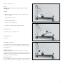
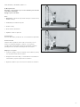
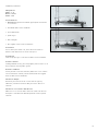
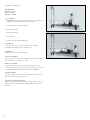
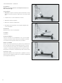
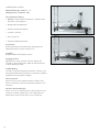
INSTALL THE BLACK PLUNGER KNOBS
3. Look through the large
threaded hole in the
trunnion and line it up
with one of the holes
in the frame.Screw the
plunger knob into the large
hole until it is completely
threaded in.See Figure D.
4. Repeat on other side.
Tighten both plunger knobs
securely with the included
open end wrench.
To move the trunnions, pull the ball of the plunger knobs away
from the frame and turn 90° to lock out. To re-engage the
plunger turn the knob until it snaps into one of the holes in
the side of frame.
Note: Make sure both trunnion
plates are locked in the same
horizontal position before
moving on.
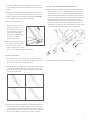
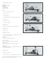
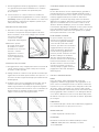
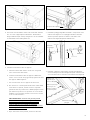
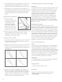
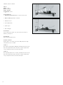
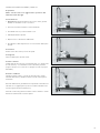
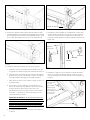
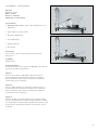
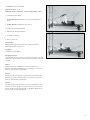
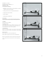
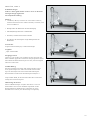
INSTALL THE FOOTBAR
5. Pick up the footbar so the
seam of the footbar cover is
away from the carriage pad.
6. While squeezing the footbar
plunger levers, guide the
footbar over the outsides of
the trunnion plates. Align
each footbar pin with the
top hole in the trunnion
plate. While continuing to
support the footbar, release
the footbar plunger levers
to engage the trunnion
plate. Be sure the pins on
both sides are engaged.
See Figure E.
Figure A
Figure B
Figure C
Figure D
Plunger
Knob
Trunnion
Plate
Figure E
Plunger
Lever
Trunion Plate
Top Hole
Washer
Shoulder Bolt

11
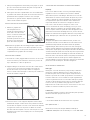
7. Pivot the footbar slightly until the large hole at the bottom
of the footbar aligns with the remaining hole in the trunnion
plate.
8. Slide the shoulder bolt with one washer through the large
footbar hole. Then screw the shoulder bolt into the trunnion
plate as tightly as possible with the large Allen (GEN9050)
wrech. Repeat on the other side. See Figure E.
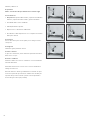
INSTALL THE RISERS
9. Remove locking pins from
the frame. Insert the risers
through the holes on the
top of the frame. Turn the
risers until the attached
pulleys point straight down
the frame toward the
footbar. See Figure F.
10. Reinsert locking pins until
the metal ring touches the
frame. You may need to
jiggle or slightly lift or rotate
the riser to get the locking pins in all the way.
ATTACH THE ROPES
11. To attach the ropes, first engage at least one spring from
the carriage to the frame to keep the carriage in the home
position. Unroll the ropes and separate them.
12. The Allegro now comes with Soft Touch Ropes that do not have
the dog-clips to attach the loops. The clip will no longer drag
on or bang into the frame! Follow the images below to install
your loops. See Figure G.
13. Rest the loops over the shoulder rests. Thread the other end of
each rope through a riser pulley and back into the cam cleats
on the carriage to adjust the length. Be sure to go through the
chrome eyestraps on both sides of the cam cleats. Always push
the rope firmly down into the cleats to ensure a good grip.
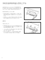
INSTALL THE TRANSPORT WHEEL BRACKET
14. Remove the 1/4”-20 button head screw and the split washer
attached to the last hole in the frame towards the footend of
the reformer, as shown in Figure H, using the 5/32” Allen key.
Slide the preassembled transport bracket into the channel in
the rail at the foot end of the reformer. Line up the hole in the
transport bracket with the hole in the frame rail. Use the
1/4”-20 button head screw and the split washer to attach the
transport bracket on to the frame using the 5/32” Allen key.
See Figure H for reference. Note: The wheel goes on the inside
of the bracket (towards the frame) when it is mounted.
15. Repeat this for the other side of the reformer.
Figure F
Locking Pin
Figure G
21
3 4
Figure H
GEN9054
618-008
GEN9472

12
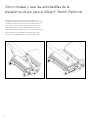
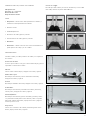
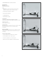
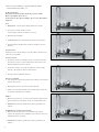
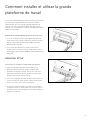
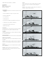
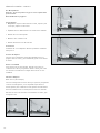
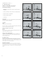
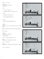
STORING THE ALLEGRO REFORMER
Stacking
To see a demonstration of how to stack the Allegro, watch the
Setup and Safety portion of the Allegro Introductory/Level 1 DVD.
Attach the springs to keep the carriage from moving. Move the
footbar to the “down” position. Remove the shoulder rests and
store in the slots at the head of the frame. Put the head rest
down. Remove the risers and store in the holes on the sides of
the frame. Place the ropes and loops inside the Allegro frame not
on the carriage. Alternate the orientation of the Allegros as you
stack them. Place the head end feet onto the standing platform
of the Allegro below, and so on. Stack a maximum of 5 reformers
with no legs (3 with legs). Do not stack Reformer with Towers.
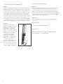
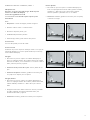
Standing
It is absolutely critical that
the Allegro footbar be set and
locked in the correct position
for standing storage. Move
and lock the footbar into the
position closest to the foot-end
of the Reformer frame. Raise
the footbar to its highest
position. Lift the head-end
of the Allegro frame to waist
height. Then raise the frame
to vertical. Use your foot to
steady the wheeled end of the
frame as you lift to vertical.
The vertical Allegro will come
to rest on the footbar and the
transport wheels. See Figure H.
CLEANING & MAINTENANCE
Cleaning
Wipe the carriage pad, headrest, footbar and shoulder rests with
a soft cloth and a mild, non-abrasive cleaner after each use.
Keep the carriage track and wheels clean from dust and dirt.
Wipe the entire track with a towel regularly. Clean the footbar
trunnion track weekly. Clean the frame with a mild, non-abrasive
cleaner. Keep the ropes and springs clear of dust. Cotton loops
can be machine-washed. Hang to dry.
Lubrication
The foot bar trunnion C-channel can be lubricated with dry
silicone spray.
MAINTENANCE
»See the included Safety First Guide.
QUESTIONS?
Call Balanced Body technical support at 1-800-745-2838
(US and Canada), or +1-916-388-2838.
Figure H

13
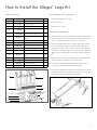
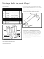
How to Install the Allegro® Legs Kit
PARTS INCLUDED:
Item No. Part Number Description Qty
1618-030 Allegro Leg, A 2
2618-031 Allegro Leg, B 2
3618-021 Leg Nut Plate 2
4614-020 Wheel Bracket, Allegro Ext
Leg 2
5GEN8320 Allen Key, 3/16” Ball Point 1
6GEN7321 Screw, Button Head, 5/16-18
x 3/4” 12
7GEN7325 Screw, 1/4-20 x 3/4” 4
8GEN9021 Nut, Nylock, 1/4-20 4
9GEN9282 Allen Key 5/32” Short Arm 1
10 618-135 Polyurethane Foot Pads 4
11 GEN9600 Double Sided Tape 4
12 GEN6742 Flat Head Screw 10-24 x
5/8” 4
13 GEN9856 #10 Flat Washer 4
14 GEN9059 #10 Nylon Nut 4
15 GEN9284 1/8” Allen Wrench 1
16 FAK1000 Alcohol Wipe 4
TOOLS NEEDED (NOT INCLUDED):
»Two 1/2” or adjustable wrenches
»One 7/16” wrench
»3/8” wrench or socket
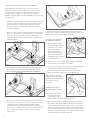
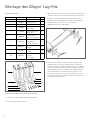
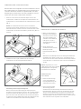
PREPARE THE NEW PADS
1. Remove the legs and other materials from the packaging and
lay the legs on the floor with the bottom of the leg facing up,
so the “L” shape face with three holes are on the floor
2. Remove the (4) Polyurethane foot pads, and (1) Alcohol wipe
from the packaging. Open one wipe and thoroughly wipe
down the top side of each foot pad. This is the side opposite
the ribbing. If the wipe is dirty or becomes too dry use another
wipe for the remaining pads. Set the pads aside and let these
dry.
3. Open an Alcohol wipe to clean the bottom of each metal foot
on the reformer. If needed use a secondary wipe.
4. If you have a Tower Of Power installed, remove the ropes,
loosen the 4 tower knobs, and remove the tower.
5. Using the included shorter allen wrench, remove the 4 screws
holding the head end cover plates and riser pins in place. Set
them aside to be re-installed later. See Figure A.
1
2
10
3
5
49
76
8
13
16
11
15
14 12
Figure A

14
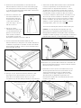
1. Attach all springs to keep the carriage stationary. Remove
ropes, shoulder rests, and risers. Place the footbar (if installed)
in its lowest position and check that all pins are locked so that
the footbar is secure. Then, with the help of a friend, lift the
Allegro from both ends and carefully turn it upside down and
set it on the floor. You may want to place a pad or other floor
protection beneath the Reformer.
2. Remove the 4 rubber feet from the bottom of the Reformer
frame by grasping them firmly with your hand and turning
counter-clockwise. You can discard the feet unless you may
want to convert back to a flat Allegro configuration.
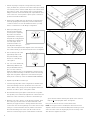
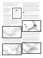
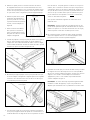
3. Before proceeding ensure
the tops of the new pads
from step 2 are completely
dry and no more alcohol
liquid remains on the part. If
the pads are not dry, the pad
and tape will not bond. Peel
one side of tape off the
sticker and install it on a
pad. Align the 45 degree
corner side of the tape with the stepped corner of the foot pad.
The center hole will go over the raised center circle. See Figure B.
4. Peel off the top side of the
applied tape and install
this pad assembly on the
bottom of a cleaned leg.
See Figure C.
5. Use one of each: #10 screw,
#10 washer, #10 nut and
the provided Allen wrench,
plus a socket or wrench;
Align the stepped corner of the pad with the opening of the
leg. The raised center will go inside the center hole in the leg.
Again refer to Figure C. Tighten the screw until the end just
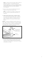
barely sticks out the top of the nut. DO NOT OVER TIGHTEN.
6. Repeat steps 8-10 for all other legs.
7. Insert the leg nut plates shown in Figure D into the Reformer
frame until the big hole lines up with the riser hole in the
frame. When it does, drop your riser through the frame and
the block to hold it in place. See Figure D and E.
8. Now maneuver the leg nut plate so that the holes in Figure E
line up when you look down through the hole in the frame. This
will be one of the screw holes you will use to attach the legs.
9. With the risers still in place to locate the leg nut plates, place
two of the legs onto the frame rail at the head end of the
Reformer, lining up the holes in the leg with the three holes
in the frame. The left and right legs are not the same so keep
looking for one that matches the hole pattern in the frame.
Now start threading all six of the 5/16-18 screws into the
frame to secure the legs in place. Start with the screws that
go into the block that is held in place by the risers and once
they are all started, tighten them. See Figure F.
Now you can remove the risers and set them aside.
NOTE: the long end of the included 3/16” allen wrench is ball
shaped to allow for more maneuverability when working in small
areas. Once the screws are finger tight, use the short leg of the
allen wrench to tighten the screws.
Figure B
Figure C
Figure D
Figure E
Make sure these holes line up.
Figure F

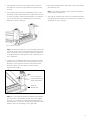
15
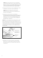
1. Install the legs onto the foot end of the frame in the same
way with the 6 screws. No leg nut plates are required at the
foot end.
2. Using a 7/16” wrench and the included allen wrench, install
the transport wheel brackets with the 1/4-20 screws and nuts
as shown in Figure G. Make sure the brackets are oriented as
shown. Typically these are installed at the foot end of the
Reformer as shown in Figure G.
NOTE: The transport wheels can also be installed at the head
end which allows you to move the Reformer with Tower more
easily. Just make sure the carriage is rolled to the head end
of the Reformer before lifting the foot end of the machine in
this configuration.
3. Using two 1/2” or adjustable wrenches, remove the transport
wheels from their current location and install them onto the
brackets you just installed. Leave the old transport wheel
brackets in place, as that is where a footstrap can be
attached. See Figure H.
NOTE: It is critical that the washers and wheel get installed in
the same order and orientation as they were on the original
brackets. Do one wheel at a time and if the wheel does not
spin freely after you are done, double check against the other
wheel to make sure everything is in the right order.
4. Re-install the head end rail cover plates on the same side you
removed them from.
NOTE: If you will be installing a Tower System next, leave the
head end rail cover plates off.
5. Your legs are installed and you may now carefully lift and turn
your Allegro Reformer back over onto the legs. Re-install your
shoulder rests, risers, and ropes.
Figure G (Footbar not shown)
Figure H
Do not forget this
washer between the
wheel and bracket.
Leave this
bracket here.

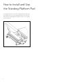
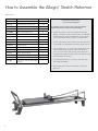
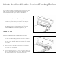
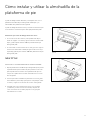
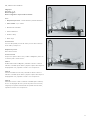
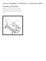
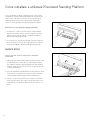
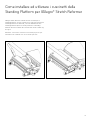
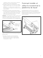
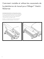
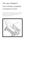
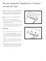
How to Install and Use
the Standing Platform Pad
Your Allegro Reformer comes with a standing platform pad. Place
the pad directly on top of the standing platform to use. This pad
will make the standing platform height the same as your carriage
pad. See Figure A.
Figure A
16

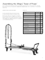
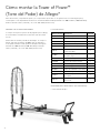
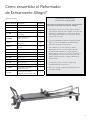
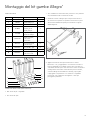
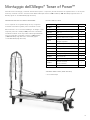
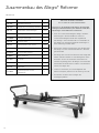
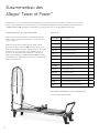
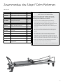
Assembling the Allegro® Tower of Power™
Prior to assembly, check the parts and components received against the following list. If you are missing any parts, contact the
Balanced Body customer service department at 1-800-PILATES (1-800-745-2837) in the U.S. and Canada, or +1-916-388-2838
(international).
PREPARE YOUR ALLEGRO REFORMER
If you have purchased an Allegro 14” leg set, we strongly
recommend installing the legs before installing the Tower.
Remove all ropes and risers from the Allegro. If your Allegro
was purchased before February 1, 2004, remove the labels and
backing on the sides. You can order a new label free of charge by
calling 1-800-PILATES (1-800-745-2837 in the U.S. and Canada,
or +1-916-388-2838 (international).
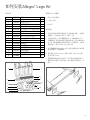
PARTS LIST
Description Part Number Qty
Tower 618-024 1
Push-through bar (PTB) TRP0047 1
T-pin GEN9892 2
Tower Bracket, Right 950-234 1
Tower Bracket, Left 950-235 1
Adjustable pulley and knob assembly 950-131 2
5/32” Allen key, long 212-001 1
Blue trap spring SPR9004 2
Yellow trap spring SPR9002 2
Long spring, purple SPR9461 2
Long spring, yellow SPR9006 2
Roll down bar 710-010 1
Single cotton loops 101-005 1 pair
Safety strap with carabiner 210-023 1
Tower lower spring mounts 950-236 1
17

18
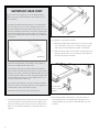
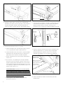
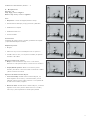
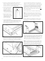
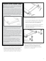
IMPORTANT: READ FIRST
NOTE: If you have an original version of the Allegro with the
angled corner joints (Serial Number less than 36396), follow
these instructions.
a. Using the provided 5/32” Allen wrench, loosen and remove
the six screws (one on each side of the Reformer and 4 on
the head end) that hold the head end of the frame on. If you
have legs installed you will have to remove the leg bolts that
attach to the head end of the frame. Take note of how the
plastic shims between the frame members are oriented and
how they fit.
Head End
b. Install the Tower brackets as described in step number 3
below. Do not tighten the bracket screws.
c. Re-install the head end of your Reformer frame with the
plastic shims and screws removed in step a. The two shorter
bolts go in the sides of the frame and the 4 longer ones go in
from the head end. Get all 6 screws started, then tighten the
screws until they are snug; do not over tighten them. If you
have legs, reinstall those bolts also.
d. Position the Tower brackets so they line up with the edge of
the frame screws on the side of the frame. Then tighten the
Tower bracket screws as described in step 4.
e. Follow the instructions from step 6 until the end.
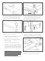
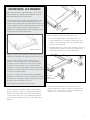
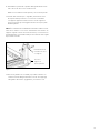
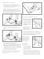
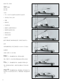
1. Using the provided 5/32” allen wrench, remove the plastic rail
caps and locking pins at the head end of the Allegro frame.
They will need to go back on the same side, so keep track of
which one goes where and keep the screws with them. See
Figure A.
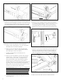
2. Installing the Tower Mount Brackets:
a. With the provided 5/32” allen wrench, loosen the 6 screws
on each bracket 1-2 turns. Do not remove them, you just
want some free play between the plates. See Figure B..
b. Make sure the brackets are oriented as in Figure B (use the
large grey knobs and screws as reference) and slide them
into the C-channel of the frame.
3. Re-install the plastic rail end caps on the same side you
removed them from. The lanyard and locking pins are no
longer needed so they can be set aside with the risers. See
Figure C.
Figure B
Loosen these
screws on both
brackets.
Figure A
La page est en cours de chargement...
La page est en cours de chargement...
La page est en cours de chargement...
La page est en cours de chargement...
La page est en cours de chargement...
La page est en cours de chargement...
La page est en cours de chargement...
La page est en cours de chargement...
La page est en cours de chargement...
La page est en cours de chargement...
La page est en cours de chargement...
La page est en cours de chargement...
La page est en cours de chargement...
La page est en cours de chargement...
La page est en cours de chargement...
La page est en cours de chargement...
La page est en cours de chargement...
La page est en cours de chargement...
La page est en cours de chargement...
La page est en cours de chargement...
La page est en cours de chargement...
La page est en cours de chargement...
La page est en cours de chargement...
La page est en cours de chargement...
La page est en cours de chargement...
La page est en cours de chargement...
La page est en cours de chargement...
La page est en cours de chargement...
La page est en cours de chargement...
La page est en cours de chargement...
La page est en cours de chargement...
La page est en cours de chargement...
La page est en cours de chargement...
La page est en cours de chargement...
La page est en cours de chargement...
La page est en cours de chargement...
La page est en cours de chargement...
La page est en cours de chargement...
La page est en cours de chargement...
La page est en cours de chargement...
La page est en cours de chargement...
La page est en cours de chargement...
La page est en cours de chargement...
La page est en cours de chargement...
La page est en cours de chargement...
La page est en cours de chargement...
La page est en cours de chargement...
La page est en cours de chargement...
La page est en cours de chargement...
La page est en cours de chargement...
La page est en cours de chargement...
La page est en cours de chargement...
La page est en cours de chargement...
La page est en cours de chargement...
La page est en cours de chargement...
La page est en cours de chargement...
La page est en cours de chargement...
La page est en cours de chargement...
La page est en cours de chargement...
La page est en cours de chargement...
La page est en cours de chargement...
La page est en cours de chargement...
La page est en cours de chargement...
La page est en cours de chargement...
La page est en cours de chargement...
La page est en cours de chargement...
La page est en cours de chargement...
La page est en cours de chargement...
La page est en cours de chargement...
La page est en cours de chargement...
La page est en cours de chargement...
La page est en cours de chargement...
La page est en cours de chargement...
La page est en cours de chargement...
La page est en cours de chargement...
La page est en cours de chargement...
La page est en cours de chargement...
La page est en cours de chargement...
La page est en cours de chargement...
La page est en cours de chargement...
La page est en cours de chargement...
La page est en cours de chargement...
La page est en cours de chargement...
La page est en cours de chargement...
La page est en cours de chargement...
La page est en cours de chargement...
La page est en cours de chargement...
La page est en cours de chargement...
La page est en cours de chargement...
La page est en cours de chargement...
La page est en cours de chargement...
La page est en cours de chargement...
La page est en cours de chargement...
La page est en cours de chargement...
La page est en cours de chargement...
La page est en cours de chargement...
La page est en cours de chargement...
La page est en cours de chargement...
La page est en cours de chargement...
La page est en cours de chargement...
La page est en cours de chargement...
La page est en cours de chargement...
La page est en cours de chargement...
La page est en cours de chargement...
La page est en cours de chargement...
La page est en cours de chargement...
La page est en cours de chargement...
La page est en cours de chargement...
La page est en cours de chargement...
La page est en cours de chargement...
La page est en cours de chargement...
La page est en cours de chargement...
La page est en cours de chargement...
La page est en cours de chargement...
La page est en cours de chargement...
La page est en cours de chargement...
La page est en cours de chargement...
La page est en cours de chargement...
La page est en cours de chargement...
La page est en cours de chargement...
La page est en cours de chargement...
La page est en cours de chargement...
La page est en cours de chargement...
La page est en cours de chargement...
La page est en cours de chargement...
La page est en cours de chargement...
La page est en cours de chargement...
La page est en cours de chargement...
La page est en cours de chargement...
La page est en cours de chargement...
La page est en cours de chargement...
La page est en cours de chargement...
La page est en cours de chargement...
La page est en cours de chargement...
La page est en cours de chargement...
La page est en cours de chargement...
La page est en cours de chargement...
La page est en cours de chargement...
La page est en cours de chargement...
La page est en cours de chargement...
La page est en cours de chargement...
La page est en cours de chargement...
La page est en cours de chargement...
La page est en cours de chargement...
La page est en cours de chargement...
La page est en cours de chargement...
La page est en cours de chargement...
La page est en cours de chargement...
La page est en cours de chargement...
La page est en cours de chargement...
La page est en cours de chargement...
La page est en cours de chargement...
La page est en cours de chargement...
La page est en cours de chargement...
La page est en cours de chargement...
La page est en cours de chargement...
La page est en cours de chargement...
La page est en cours de chargement...
La page est en cours de chargement...
La page est en cours de chargement...
La page est en cours de chargement...
La page est en cours de chargement...
La page est en cours de chargement...
La page est en cours de chargement...
La page est en cours de chargement...
La page est en cours de chargement...
La page est en cours de chargement...
La page est en cours de chargement...
La page est en cours de chargement...
La page est en cours de chargement...
La page est en cours de chargement...
La page est en cours de chargement...
La page est en cours de chargement...
La page est en cours de chargement...
La page est en cours de chargement...
La page est en cours de chargement...
La page est en cours de chargement...
La page est en cours de chargement...
La page est en cours de chargement...
La page est en cours de chargement...
La page est en cours de chargement...
La page est en cours de chargement...
La page est en cours de chargement...
La page est en cours de chargement...
La page est en cours de chargement...
La page est en cours de chargement...
La page est en cours de chargement...
La page est en cours de chargement...
La page est en cours de chargement...
La page est en cours de chargement...
La page est en cours de chargement...
La page est en cours de chargement...
La page est en cours de chargement...
La page est en cours de chargement...
La page est en cours de chargement...
La page est en cours de chargement...
La page est en cours de chargement...
La page est en cours de chargement...
La page est en cours de chargement...
La page est en cours de chargement...
La page est en cours de chargement...
La page est en cours de chargement...
La page est en cours de chargement...
La page est en cours de chargement...
La page est en cours de chargement...
La page est en cours de chargement...
La page est en cours de chargement...
La page est en cours de chargement...
La page est en cours de chargement...
La page est en cours de chargement...
La page est en cours de chargement...
La page est en cours de chargement...
La page est en cours de chargement...
La page est en cours de chargement...
La page est en cours de chargement...
La page est en cours de chargement...
La page est en cours de chargement...
La page est en cours de chargement...
La page est en cours de chargement...
La page est en cours de chargement...
La page est en cours de chargement...
La page est en cours de chargement...
La page est en cours de chargement...
La page est en cours de chargement...
La page est en cours de chargement...
La page est en cours de chargement...
La page est en cours de chargement...
La page est en cours de chargement...
La page est en cours de chargement...
La page est en cours de chargement...
La page est en cours de chargement...
La page est en cours de chargement...
La page est en cours de chargement...
La page est en cours de chargement...
La page est en cours de chargement...
La page est en cours de chargement...
La page est en cours de chargement...
La page est en cours de chargement...
La page est en cours de chargement...
La page est en cours de chargement...
La page est en cours de chargement...
La page est en cours de chargement...
La page est en cours de chargement...
La page est en cours de chargement...
La page est en cours de chargement...
La page est en cours de chargement...
La page est en cours de chargement...
La page est en cours de chargement...
La page est en cours de chargement...
La page est en cours de chargement...
La page est en cours de chargement...
La page est en cours de chargement...
La page est en cours de chargement...
La page est en cours de chargement...
La page est en cours de chargement...
La page est en cours de chargement...
La page est en cours de chargement...
La page est en cours de chargement...
La page est en cours de chargement...
La page est en cours de chargement...
La page est en cours de chargement...
La page est en cours de chargement...
La page est en cours de chargement...
La page est en cours de chargement...
La page est en cours de chargement...
La page est en cours de chargement...
La page est en cours de chargement...
La page est en cours de chargement...
La page est en cours de chargement...
La page est en cours de chargement...
La page est en cours de chargement...
La page est en cours de chargement...
La page est en cours de chargement...
La page est en cours de chargement...
La page est en cours de chargement...
La page est en cours de chargement...
La page est en cours de chargement...
La page est en cours de chargement...
La page est en cours de chargement...
La page est en cours de chargement...
La page est en cours de chargement...
La page est en cours de chargement...
La page est en cours de chargement...
La page est en cours de chargement...
La page est en cours de chargement...
La page est en cours de chargement...
La page est en cours de chargement...
La page est en cours de chargement...
La page est en cours de chargement...
-
 1
1
-
 2
2
-
 3
3
-
 4
4
-
 5
5
-
 6
6
-
 7
7
-
 8
8
-
 9
9
-
 10
10
-
 11
11
-
 12
12
-
 13
13
-
 14
14
-
 15
15
-
 16
16
-
 17
17
-
 18
18
-
 19
19
-
 20
20
-
 21
21
-
 22
22
-
 23
23
-
 24
24
-
 25
25
-
 26
26
-
 27
27
-
 28
28
-
 29
29
-
 30
30
-
 31
31
-
 32
32
-
 33
33
-
 34
34
-
 35
35
-
 36
36
-
 37
37
-
 38
38
-
 39
39
-
 40
40
-
 41
41
-
 42
42
-
 43
43
-
 44
44
-
 45
45
-
 46
46
-
 47
47
-
 48
48
-
 49
49
-
 50
50
-
 51
51
-
 52
52
-
 53
53
-
 54
54
-
 55
55
-
 56
56
-
 57
57
-
 58
58
-
 59
59
-
 60
60
-
 61
61
-
 62
62
-
 63
63
-
 64
64
-
 65
65
-
 66
66
-
 67
67
-
 68
68
-
 69
69
-
 70
70
-
 71
71
-
 72
72
-
 73
73
-
 74
74
-
 75
75
-
 76
76
-
 77
77
-
 78
78
-
 79
79
-
 80
80
-
 81
81
-
 82
82
-
 83
83
-
 84
84
-
 85
85
-
 86
86
-
 87
87
-
 88
88
-
 89
89
-
 90
90
-
 91
91
-
 92
92
-
 93
93
-
 94
94
-
 95
95
-
 96
96
-
 97
97
-
 98
98
-
 99
99
-
 100
100
-
 101
101
-
 102
102
-
 103
103
-
 104
104
-
 105
105
-
 106
106
-
 107
107
-
 108
108
-
 109
109
-
 110
110
-
 111
111
-
 112
112
-
 113
113
-
 114
114
-
 115
115
-
 116
116
-
 117
117
-
 118
118
-
 119
119
-
 120
120
-
 121
121
-
 122
122
-
 123
123
-
 124
124
-
 125
125
-
 126
126
-
 127
127
-
 128
128
-
 129
129
-
 130
130
-
 131
131
-
 132
132
-
 133
133
-
 134
134
-
 135
135
-
 136
136
-
 137
137
-
 138
138
-
 139
139
-
 140
140
-
 141
141
-
 142
142
-
 143
143
-
 144
144
-
 145
145
-
 146
146
-
 147
147
-
 148
148
-
 149
149
-
 150
150
-
 151
151
-
 152
152
-
 153
153
-
 154
154
-
 155
155
-
 156
156
-
 157
157
-
 158
158
-
 159
159
-
 160
160
-
 161
161
-
 162
162
-
 163
163
-
 164
164
-
 165
165
-
 166
166
-
 167
167
-
 168
168
-
 169
169
-
 170
170
-
 171
171
-
 172
172
-
 173
173
-
 174
174
-
 175
175
-
 176
176
-
 177
177
-
 178
178
-
 179
179
-
 180
180
-
 181
181
-
 182
182
-
 183
183
-
 184
184
-
 185
185
-
 186
186
-
 187
187
-
 188
188
-
 189
189
-
 190
190
-
 191
191
-
 192
192
-
 193
193
-
 194
194
-
 195
195
-
 196
196
-
 197
197
-
 198
198
-
 199
199
-
 200
200
-
 201
201
-
 202
202
-
 203
203
-
 204
204
-
 205
205
-
 206
206
-
 207
207
-
 208
208
-
 209
209
-
 210
210
-
 211
211
-
 212
212
-
 213
213
-
 214
214
-
 215
215
-
 216
216
-
 217
217
-
 218
218
-
 219
219
-
 220
220
-
 221
221
-
 222
222
-
 223
223
-
 224
224
-
 225
225
-
 226
226
-
 227
227
-
 228
228
-
 229
229
-
 230
230
-
 231
231
-
 232
232
-
 233
233
-
 234
234
-
 235
235
-
 236
236
-
 237
237
-
 238
238
-
 239
239
-
 240
240
-
 241
241
-
 242
242
-
 243
243
-
 244
244
-
 245
245
-
 246
246
-
 247
247
-
 248
248
-
 249
249
-
 250
250
-
 251
251
-
 252
252
-
 253
253
-
 254
254
-
 255
255
-
 256
256
-
 257
257
-
 258
258
-
 259
259
-
 260
260
-
 261
261
-
 262
262
-
 263
263
-
 264
264
-
 265
265
-
 266
266
-
 267
267
-
 268
268
-
 269
269
-
 270
270
-
 271
271
-
 272
272
-
 273
273
-
 274
274
-
 275
275
-
 276
276
-
 277
277
-
 278
278
-
 279
279
-
 280
280
-
 281
281
-
 282
282
-
 283
283
-
 284
284
-
 285
285
-
 286
286
-
 287
287
-
 288
288
-
 289
289
-
 290
290
-
 291
291
-
 292
292
-
 293
293
-
 294
294
-
 295
295
-
 296
296
-
 297
297
-
 298
298
-
 299
299
-
 300
300
-
 301
301
-
 302
302
-
 303
303
-
 304
304
-
 305
305
-
 306
306
-
 307
307
-
 308
308
-
 309
309


Balanced Body Allegro Reformer Manuel utilisateur
- Taper
- Manuel utilisateur
- Ce manuel convient également à
dans d''autres langues
Autres documents
-
Teeter 700ia Assembly Instructions
-
MOB MO6434 Manuel utilisateur
-
 Outsunny 84C-120GY Mode d'emploi
-
Baby Jogger City Mini Zip Assembly Instructions Manual
-
Malaguti CIAK 150 Manuel utilisateur
-
-
Gima 28318 Le manuel du propriétaire
-
Hafele 641.06.913 Manuel utilisateur
-
Toro 48" Snowthrower, Groundsmaster 52/72 and GMT Guide d'installation
-
 MSR Revo™ Trail Snowshoes Mode d'emploi

