Moxa EDS-510E Series Guide d'installation rapide
- Catégorie
- Commutateurs réseau
- Taper
- Guide d'installation rapide

P/N: 1802005100044
*1802005100044*
EDS-510E Series
Quick Installation Guide
Moxa EtherDevice™ Switch
Version 1.4, June 2023
Technical Support Contact Information
www.moxa.com/support
2023 Moxa Inc. All rights reserved.

- 2 -
Package Checklist
The EDS-510E is shipped with the following items. If any of these items
are missing or damaged, please contact your customer service
representative for assistance.
• 1 EDS-510E Ethernet switch
• USB cable
• Protective caps for unused ports
• Quick installation guide (printed)
• Warranty card
Features
• 2 Gigabit Ethernet ports for redundant ring and 1 Gigabit Ethernet
port for uplink solution
• Turbo Ring and Turbo Chain (recovery time < 20 ms @ 250
switches), RSTP/STP, and MSTP for network redundancy
• RADIUS, TACACS+, SNMPv3, IEEE 802.1x, HTTPS, and SSH to
enhance network security
• EtherNet/IP, PROFINET, and Modbus/TCP protocols supported for
device management and monitoring

- 3 -
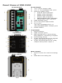
Panel Views of EDS-510E
Front Panel
Top Panel
Rear Panel
Front Panel
1.
1 to 7 port status LED
2.
1 to 7: 10/100BaseT(X) port
3.
System status LED:
• STATE LED indicator
• PWR1 LED indicator
• PWR2 LED indicator
• FAULT LED indicator
• MSTR/HEAD LED indicator
• CPLR/TAIL LED indicator
4.
USB storage port
5.
G1 to G3 port status LED
6.
G1 to G3:
10/100/1000BaseT(X) or
100/1000BaseSFP combo port
7.
Model Name
Top Panel
1.
Reset button
2.
USB console port
3.
DIP switches for Turbo Ring,
Ring Master, and Ring Coupler
4.
Grounding screw
5.
4-pin terminal block for digital
input and power input 2
6.
4-pin terminal block for relay
output and power input 1
Rear Panel
1.
Screw holes for wall mounting
kit
2.
DIN-Rail mounting kit

- 4 -
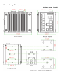
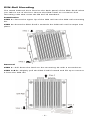
Mounting Dimensions
Unit = mm (inch)

- 5 -
DIN-Rail Mounting
The metal DIN-rail kit is fixed to the back panel of the EDS-510E when
you take it out of the box. Mount the EDS-510E on corrosion-free
mounting rails that meet the EN 60715 standard.
Installation
STEP 1—Insert the upper lip of the DIN rail into the DIN-rail mounting
kit.
STEP 2—Press the EDS-510E t towards the DIN rail until it snaps into
place.
Removal
STEP 1—Pull down the latch on the mounting kit with a screwdriver.
STEP 2 & 3—Slightly pull the EDS-510E forward and lift up to remove
it from the DIN rail.

- 6 -
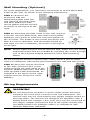
Wall Mounting (Optional)
For some applications, you will find it convenient to mount Moxa EDS-
510E on the wall, as shown in the following illustrations:
STEP 1—Remove the
aluminum DIN r
ail
attachment plate from the
rear p
anel of the EDS-510E,
and then attach the wall
mount plates
with M3 screws
,
as shown
in the figure at the
right.
STEP 2
—Mounting the EDS-510E
on the wall requires
4 screws. Use the
EDS-510E, with wall mount plates
attached, as a guide to mark the correct locations of
the 4 screws. The heads of the screws should be less
than 6.0 mm in diameter, and the shafts should be
less than 3.5
mm in diameter, as shown in the figure
on at right.
NOTE
Before tightening the screws into the wall, make sure the screw
head and shank size are suitable by inserting the screw through
one of the keyhole
-shaped apertures of the Wall Mounting
Plates.
Do not screw the screws in all the way—leave about 2 mm to allow
room for sliding the wall mount panel between the wall and the screws.
STEP 3—Once the screws are fixed
to
the wall, insert the four screw
heads through the wide parts of the
keyhole
-
shaped apertures, and then
slide
the EDS-510E downwards, as
indicated
in the figure at the right.
Tighten the four screws for
more
stability
.
Wiring Requirements
WARNING
Do not disconnect modules or wires unless power has been
switched off or the area is known to be non
-hazardous. The
devices may only be connected to the supply voltage shown on
the type plate. The devices are designed for operation with a
S
afety Extra-Low V
oltage. Thus, they may only be connected to
the supply voltage connections and to the signal contact with
the
Safety Extra-Low Voltages (SELV) in compliance with
IEC950/ EN60950/ VDE0805.

- 7 -
ATTENTION
This unit is a built
-in type. When the unit is installed in another
piece of equipment, the equipment enclosing the unit must
comply with fire enclosure regulation IEC 60950/EN60950 (or
similar regulation).
ATTENTION
Safety First!
Be sure to disconnect the power cord before installing and/or
wiring your Moxa EtherDevice Switch.
Calculate the maximum possible current in each power wire and
common wire. Observe all electrical codes dictating the
maximum current allowable for each wire
size.
If the current goes above the maximum ratings, the wiring
could overheat, causing serious damage to your equipment.
Please read and follow these guidelines:
• Use separate paths to route wiring for power and devices. If power
wiring and device wiring paths must cross, make sure the wires are
perpendicular at the intersection point.
NOTE: Do not run signal or communications wiring and power
wiring through the same wire conduit. To avoid interference, wires
with different signal characteristics should be routed separately
• You can use the type of signal transmitted through a wire to
determine which wires should be kept separate. The rule of thumb
is that wiring that shares similar electrical characteristics can be
bundled together
• You should separate input wiring from output wiring
• We advise that you label the wiring to all devices in the system.
Grounding the Moxa EDS-510E
Grounding and wire routing help limit the effects of noise due to
electromagnetic interference (EMI). Run the ground connection from
the ground screw to the grounding surface prior to connecting devices.
ATTENTION
This product is intended to be mounted to a well
-grounded
mounting surface such as a metal panel.
Wiring the Relay Contact
The EDS-510E has one set of relay output. This relay contact uses two
contacts of the terminal block on the EDS-510E’s top panel. Refer to
the next section for detailed instructions on how to connect the wires to
the terminal block connector, and how to attach the terminal block
connector to the terminal block receptor. In this section, we illustrate
the use of two contacts used to connect the relay.

- 8 -
FAULT: The two contacts of the 6-pin
terminal block connector are used to
detect user
-configured events. The
t
wo wires attached to the fault
contacts form an open circuit when a
user
-configured event is triggered. If
a user
-configured event does not
occur, the
fault circuit remains
closed.
Wiring the Redundant Power Inputs
The EDS-510E has two sets of power inputs—power input 1 and power
input 2. The top and front views of one of the terminal block connectors
are shown here.
Input Terminal Block:
Suitable for 12
-28 AWG
(3.31 to 0.081 mm
2) wire size,
torque value 4.5 lb
-in
(0.
509 N-m)
Use Copper conductors only.
STEP 1: Insert the negative/positive
DC wires into the V
-/V+ terminals,
respectively.
STEP 2:
To keep the DC wires from
pulling loose, use a small flat
-blade
screwdriver to tighten the wire
-cl
amp
screws on the front of the terminal
block connector.
STEP 3:
Insert the plastic terminal
block connector prongs into the
terminal block receptor, which is
located on the EDS-510E’s top panel.
Wiring the Digital Inputs
The EDS-510E has one set of digital input (DI). The DI consists of two
contacts of the 4-pin terminal block connector on the EDS-510E's top
panel, which are used for the two DC inputs. The top and front views of
one of the terminal block connectors are shown here.
STEP 1: Insert the negative
(ground)/positive DI wires into the
┴
/I terminals
, respectively.
STEP 2:
To keep the DI wires from
pulling loose, use a small flat
-blade
screwdriver to tighten the wire
-
clamp
screws on the front of the terminal
block connector.
STEP 3:
Insert the plastic terminal
block connector prongs into the
terminal block receptor, which is
located on the EDS-510E’s top panel.
Communication Connections
Each EDS-510E switch has 4 types of communication ports:
• 1 USB console port (type B connector)
• 1 USB storage port (type A connector)
• 7 10/100BaseTX Ethernet ports
• 3 Gigabit Ethernet ports:
3 10/100/1000BaseTX and 3 100/1000BaseSFP ports

- 9 -
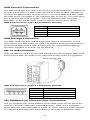
USB Console Connection
The EDS-510E has one USB console port (type B connector), located on
the top panel. Use the USB cable (provided in the product package) to
connect the EDS-510E's console port to your PC's USB port and install
the USB driver (available in the software CD) on the PC. You may then
use a console terminal program, such as Moxa PComm Terminal
Emulator, to access the EDS-510E’s console configuration utility.
USB Console Port (Type B Connector) Pinouts
Pin
Description
1
D– (Data -)
2
VCC (+5V)
3
D+ (Data+)
4
GND (Ground)
USB Storage Connection
The EDS-510E has one USB storage port (type A connector) on the
front panel. Use Moxa ABC-02-USB-T automatic backup configurator to
connect the EDS-510E's USB storage port for configuration backup,
firmware upgrade or system log file backup.
ABC-02-USB Installation
Plug the ABC-02-USB into the USB storage port of the Moxa EDS-510E.
Securing the ABC-02-USB on the wall with an M4 screw is suggested.
USB Storage Port (Type A Connector) Pinouts
Pin
Description
1
VCC (+5V)
2
D– (Data -)
3
D+ (Data+)
4
GND (Ground)
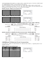
10/100BaseT(X) Ethernet Port Connection
The 10/100BaseT(X) ports located on the EDS-510E’s front panel are
used to connect to Ethernet-enabled devices. Most users configure
these ports for Auto MDI/MDI-X mode, in which case the port’s pinouts
are adjusted automatically depending on the type of Ethernet cable

- 10 -
used (straight-through or cross-over), and the type of device (NIC-type
or HUB/Switch-type) connected to the port.
In what follows, we give pinouts for both MDI (NIC-type) ports and
MDI-X (HUB/Switch-type) ports. We also give cable wiring diagrams for
straight-through and cross-over Ethernet cables.
RJ45 (8-pin, MDI) Port Pinouts
Pin
Signal
1
Tx+
2
Tx-
3
Rx+
6
Rx-
RJ45 (8-pin, MDI-X) Port Pinouts
Pin
Signal
1
Rx+
2
Rx-
3
Tx+
6
Tx-
RJ45 (8-pin) to RJ45 (8-pin) Straight-through Cable Wiring
RJ45 (8-pin) to RJ45 (8-pin) Cross-over Cable Wiring
1000BaseT Ethernet Port Connection
1000BaseT data is transmitted on differential TRD+/- signal pairs over
copper wires.
MDI/MDI-X Port Pinouts
Pin
Signal
1
TRD(0)+
2
TRD(0)-
3
TRD(1)+
4
TRD(2)+
5
TRD(2)-
6
TRD(1)-
7
TRD(3)+
8
TRD(3)-

- 11 -
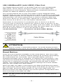
100/1000BaseSFP (mini-GBIC) Fiber Port
The gigabit Ethernet ports on the EDS-510E are 100/1000BaseSFP
Fiber ports, which require using the 100M or 1G mini-GBIC fiber
transceivers to work properly. Moxa provides completed transceiver
models for different distance requirement.
The concept behind the LC port and cable is quite straightforward.
Suppose that you are connecting devices I and II; contrary to electrical
signals, optical signals do not require a circuit in order to transmit data.
Consequently, one of the optical lines is used to transmit data from
device I to device II, and the other optical line is used transmit data
from device II to device I, for full-duplex transmission.
Remember to connect the Tx (transmit) port of device I to the Rx
(receive) port of device II, and the Rx (receive) port of device I to the
Tx (transmit) port of device II. If you make your own cable, we suggest
labeling the two sides of the same line with the same letter (A-to-A and
B-to-B, as shown below, or A1-to-A2 and B1-to-B2).
LC-Port Pinouts
LC-Port to LC-Port Cable Wiring
ATTENTION
This is a Class 1 Laser/LED product. To avoid causing serious
damage to your eyes, do not stare directly into the Laser Beam.
Reset Button
There are two functions available on the reset button. One is to reset
the Ethernet switch to factory default settings by pressing and holding
the reset button for 5 seconds. Use a pointed object, such as a
straightened paper clip or toothpick, to depress the reset button. This
will cause the STATE LED to blink once a second. After depressing the
button for 5 continuous seconds, the STATE LED will start to blink
rapidly. This indicates that factory default settings have been loaded
and you can release the reset button.
When the ABC-02-USB is connected to the EDS-510E Ethernet switch,
the reset button allows quick configuration and backs up log files to the
ABC-02-USB. Press the Reset button on top of the EDS-510E, the
Ethernet switch will start backing up current system configuration files
and event logs to the ABC-02-USB.
NOTE
Do NOT power off the Ethernet switch when loading default
settings.

- 12 -
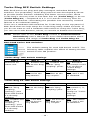
Turbo Ring DIP Switch Settings
EDS-510E series are plug-and-play managed redundant Ethernet
switches. The proprietary Turbo Ring protocol was developed by Moxa
to provide better network reliability and faster recovery time. Moxa
Turbo Ring’s recovery time is less than 300 ms (Turbo Ring) or 20 ms
(Turbo Ring V2) —compared to a 3- to 5-minute recovery time for
commercial switches—decreasing the possible loss caused by network
failures in an industrial setting.
There are 4 Hardware DIP Switches for Turbo Ring on the top panel of
EDS-510E that can help setup the Turbo Ring easily within seconds. If
you do not want to use a hardware DIP switch to setup the Turbo Ring,
you can use a web browser, telnet, or console to disable this function.
NOTE
Please refer to the
Turbo Ring section in Communication
R
edundancy User's Manual for more detail information about
the setting and usage of Turbo Ring and Turbo Ring V2.
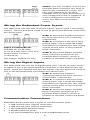
EDS-510E Series DIP Switches
The default setting for each DIP Switch is OFF. The
following table explains the effect of setting the DIP
Switch to the ON position
.
“Turbo Ring” DIP Switch Settings
DIP 1
DIP 2
DIP 3
DIP 4
Reserved for
future use.
ON: Enables this
EDS as the Ring
Master.
ON: Enables the
default “Ring
Coupling” ports.
ON: Activates
DIP switch 2 and
3 to configure
“Turbo Ring”
settings.
OFF: This EDS
will not be the
Ring Master.
OFF: Do not use
this EDS as the
ring coupler.
OFF: DIP switch
1, 2, and 3 will
be disabled.
“Turbo Ring V2” DIP Switch Settings
DIP 1
DIP 2
DIP 3
DIP 4
ON: Enables the
default “Ring
Coupling
(backup)” port
when DIP switch
3 is already
enabled.
ON: Enables this
EDS as the Ring
Master.
ON: Enables the
default “Ring
Coupling” port.
ON: Activates
DIP switch 1, 2,
and 3 to
configure “Turbo
Ring V2”
settings.
OFF: Enables the
default “Ring
Coupling
(primary)” port
when DIP switch
3 is already
enabled.
OFF: This EDS
will not be the
Ring Master.
OFF: Do not use
this EDS as a
ring coupler.
OFF: DIP switch
1, 2, and 3 will
be disabled.

- 13 -
NOTE
You must enable the Turbo Ring function first before using the
DIP switch to activate the Master and Coupler functions.
NOTE
If you do not enable any of the EDS-510E switches to be the
Ring Master, the Turbo Ring
protocol will automatically choose
the EDS
-510E with the smallest MAC address range to be the
Ring Master. If you accidentally enable more than one EDS
-
510E to be the Ring Master, these EDS
-510E switches will auto
-
negotiate to determine which one will be the Ring Master.
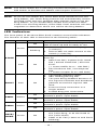
LED Indicators
The front panel of the Moxa EDS-510E contains several LED indicators.
The function of each LED is described in the following table:
LED
Color
Status
Description
STATE
Green
On The system passed the self-diagnosis
test on boot-up and is ready to run.
Blinking
1. The switch is under reset progress
(1 time/s).
2. Detect ABC-02-USB connect to the
switch (1 time/2s).
Red On
The system failed self-diagnosis on
boot-up.
• RAM Test Fail / System Info. Read
Fail / Switch Initial Fail / PTP PHY
Error.
(+ Green MSTR lit on : HW FAIL)
• FW Checksum Fail / Uncompress
Fail.
(+ Green Coupler lit on: SW FAIL)
FAULT
Red On
1. The signal contact is open.
2. ABC Loading/Saving Fail.
3. The port being disabled because of
the
ingress multicast and broadcast
packets exceed the ingress rate
limit.
4. Incorrect loop connection in a
single switch.
5. Invalid Ring port connection.
PWR1 Amber
On
Power is being supplied to the main
module’s power input PWR1.
Off Power is not being supplied to the main
module’s power input PWR1.
PWR2 Amber
On Power is being supplied to the main
module’s power input PWR2.
Off
Power is not being supplied to the main
module’s power input PWR2.
MSTR/
HEAD Green On
1. The switch is set as the Master of
the Turbo Ring, or as the Head of
the Turbo Chain.
2. POST H.W. Fail (+Stat on and Fault
blinking).

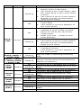
- 14 -
LED
Color
Status
Description
Blinking
1. The switch has become the Ring
Master of the Turbo Ring.
2. The Head of the Turbo Chain, after
the Turbo Ring or the Turbo Chain
is down.
3. The switch is set as Turbo Chain’s
Member and the corresponding
chain port is down.
Off
1. The switch is not the Master of this
Turbo Ring.
2. This switch is set as a Member of
the Turbo Chain.
CPLR/
TAIL Green
On
1. The switch’s coupling function is
enabled to form a back-up path.
2. When it’s set as the Tail of the
Turbo Chain.
3. POST S.W. Fail (+Stat on and
Fault blinking)
Blinking
1. Turbo Chain is down.
2. The switch is set as Turbo Chain’s
Member and the corresponding
chain port is down.
Off
1. This switch has disabled the
coupling function.
2. This switch is set as a Member of
the Turbo Chain.
FAULT +
MSTR/HEAD +
CPLR/TAIL
Rotate
Blinking
Sequentially
ABC-02-USB is importing/exporting
files.
STATE + FAULT
+ MSTR/HEAD
+ CPLR/TAIL
Blinking Switch is being discovered/located by
MXview (2 times/s).
10M/
100M
(TP)
Amber
On
TP port’s 10 or 100 Mbps link is active.
Blinking
Data is being transmitted at 10 or 100
Mbps.
Off
TP port’s 10/100 Mbps link is inactive.
1000M
(TP) Green
On
TP port’s 1000 Mbps link is active.
Blinking
Data is being transmitted at 1000
Mbps.
Off
TP port’s 1000 Mbps link is inactive.
100M
(SFP) Amber
On
SFP port’s 100 Mbps link is active.
Blinking
Data is being transmitted at 100 Mbps.
Off
SFP port’s 100 Mbps link is inactive.
1000M
(SFP) Green
On
SFP port’s 1000 Mbps link is active.
Blinking
Data is being transmitted at 1000
Mbps.
Off
SFP port’s 1000 Mbps link is inactive.

- 15 -
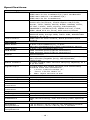
Specifications
Technology
Standards IEEE 802.3 for 10BaseT
IEEE 802.3u for 100BaseT(X) and 100BaseFX
IEEE 802.3ab for 1000BaseT(X)
IEEE 802.3z for 1000BaseX
Protocols IGMPv1/v2/v3, GMRP, GVRP, SNMPv1/v2c/v3,
DHCP Server/Client, DHCP Option 66/67/82,
BootP, TFTP, SNTP, SMTP, RARP, RMON, HTTP,
HTTPS, Telnet, SSH, Syslog, EtherNet/IP,
PROFINET, Modbus/TCP, SNMP Inform, LLDP,
IEEE 1588 PTP V2, IPv6, NTP Server/Client
MIB MIB-II, Ethernet-Like MIB, P-BRIDGE MIB, Q-
BRIDGE MIB, Bridge MIB, RSTP MIB, RMON MIB
Group 1, 2, 3, 9
Flow Control
IEEE 802.3x flow control, back pressure flow
control
Interface
RJ45 Ports 7-port 10/100BaseT(X), 3-port
10/100/1000BaseT(X) auto negotiation speed
Fiber Ports
3-port 100/1000BaseSFP slot
USB Ports USB console port (type B connector)
USB storage port (type A connector)
Button
Reset button
LED Indicators
PWR1, PWR2, FAULT, STATE, 10/100M (TP port),
100/1000M (Gigabit port), MSTR/HEAD,
CPLR/TAIL
Alarm Contact 1 relay output with current carrying capacity of 1
A @ 24 VDC
Digital Input
1 input with the same ground, but electrically
isolated from the electronics.
• +13 to +30V for state “1”
• -30 to +3V for state “0”
• Max. input current: 8 mA
Power
Input Voltage
12/24/48/-48 VDC, redundant dual inputs
Input Current
0.68 A @ 24 V
Connection
2 removable 4-contact terminal blocks
Overload Current
Protection
Present
Reverse Polarity
Protection
Present
Physical Characteristics
Housing
Metal, IP30 protection
Dimension
79.8 x 135 x 116 mm (3.13 x 5.31 x 4.57 in)
Installation
DIN-rail mounting, wall mounting (with optional
kit)
Environmental Limits
Operating
Temperature
-10 to 60°C (14 to 140°F) for standard models
-40 to 75°C (-40 to 167°F) for T models
Storage
Temperature
-40 to 85°C (-40 to 185°F)

- 16 -
Ambient Relative
Humidity
5 to 95% (non-condensing)
Altitude
Up to 2000m
Note: Please contact Moxa if you require products
guaranteed to function properly at higher
altitudes.
Regulatory Approvals
Safety
UL 508
EMI
FCC Part 15 Subpart B Class A
EMS
EN 61000-4-2 (ESD) Level 4,
EN 61000-4-3 (RS) Level 3,
EN 61000-4-4 (EFT) Level 4,
EN 61000-4-5 (Surge) Level 4,
EN 61000-4-6 (CS) Level 3, EN 61000-4-8
Maritime
DNV, LR, ABS, NKK
Shock
IEC 60068-2-27
Free Fall
IEC 60068-2-32
Vibration
IEC 60068-2-6
Warranty
Warranty
5 years
NOTE
Devices should be deployed a minimum of 600 mm from a
compass.
Hazardous Location
Trademark
Model/Rating
Model name:
EDS-510E-3GTXSFP
EDS-510E-3GTXSFP-T
Rating:
12 to 48 VDC, 1.3 A, Class 2
Relay output:
24 VDC, 1 A, Resistance
ATEX information
II 3G
DEMKO
13 ATEX 1218X
Ex nA nC IIC T4 Gc
Ambient Range: -40°C ≤ Tamb ≤ +75°C
WARNING – DO NOT SEPARATE WHEN ENERGIZED
Rated Cable Temp ≥ 84°C
Address of
manufacturer
No. 1111, Heping Rd., Bade Dist., Taoyuan City
334004, Taiwan

- 17 -
Standards and Certifications
Hazardous
Location
EN 60079-0
EN 60079-15
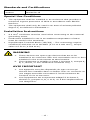
Special Use Conditions
• The equipment shall be installed in an enclosure that provides a
minimum ingress protection of IP54 in accordance with EN IEC
60079-0.
• The equipment shall only be used in an area of at least pollution
degree 2, as defined in EN 60664-1.
Installation Instructions
• A 4 mm2 conductor must be used when connecting to the external
grounding screw.
• Conductors suitable for use in an ambient temperature of 84°C
must be used for the terminals.
• Input/Output Terminal Block (JP2/JP3) – The connectors require
conductors with size 12 to 28 AWG (3.31 to 0.081 mm2), torque
value 4.5 lb-in (0.509 N-m).
WARNING
1. These devices are open-type devices that are to be
installed in an enclosure with tool-
removable cover or door
suitable for the environment at that location.
2.
This equipment is suitable in Class I, Division 2, Groups A,
B, C, and D, or non-hazardous locations only.
AVIS IMPORTANT
1. Ces appareils sont des dispositifs de type ouvert qui
doivent être installés dans un boîtier avec un
couvercle ou
une trappe amovible convenant à l'environnement de
l'endroit où ils se trouvent.
2. Cet équipement est uniquement adapté à la classe I,
division 2, groupes A, B, C et D, ou à des emplacements
non dangereux.

- 18 -
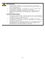
WARNING
1. EXPLOSION HAZARD - Do not disconnect equipment
unless power has been removed or the area is known to
be non-hazardous.
2. EXPLOSION HAZARD - Substitution of any components
may impair suitability for Class I, Division 2.
3. EXPOSURE TO SOME CHEMICALS MAY DEGRADE THE
SEALING PROPERTIES OF MATERIALS USED IN THE
RELAY.
AVERTISSEMENT
1. RISQUE D'EXPLOSION - Ne pas déconnecter l'équipement
si l'alimentation n'a pas été coupée ou si la zone n'est pas
considérée comme dangereuse.
2. RISQUE D'EXPLOSION - Le fait de remplacer l'un des
composants peut compromettre l'adéquation de l'appareil
de classe I, division 2.
3. L'EXPOSITION À CERTAINS PRODUITS CHIMIQUES PEUT
DÉTÉRIORER LES PROPRIÉTÉS DE SCELLEMENT DES
MATÉRIAUX UTILISÉS DANS LE RELAIS.
-
 1
1
-
 2
2
-
 3
3
-
 4
4
-
 5
5
-
 6
6
-
 7
7
-
 8
8
-
 9
9
-
 10
10
-
 11
11
-
 12
12
-
 13
13
-
 14
14
-
 15
15
-
 16
16
-
 17
17
-
 18
18


Moxa EDS-510E Series Guide d'installation rapide
- Catégorie
- Commutateurs réseau
- Taper
- Guide d'installation rapide
dans d''autres langues
Documents connexes
Autres documents
-
FS IES5100-24TF Mode d'emploi
-
Weidmueller 2682600000 Guide d'installation
-
Leonton EG5-1600-M12XB-67 Manuel utilisateur
-
FS IES3100-8TF Mode d'emploi
-
AVM FRITZ!Powerline 510E Set International Manuel utilisateur
-
Ferm HGM1003 Manuel utilisateur
-
 RED LION CONTROLS NT-5018-FX2-SC40 Fiche technique
-
 ANTAIRA LMX-0702G-SFP-V2 Series Manuel utilisateur
-
Foundry Networks FES12GCF Guide d'installation
-
red lion NT4008 Hardware Manuel utilisateur

