
31-5000582 Rev. 0 01-21 GEA
RAKUVC1 and RAKUVC2 kits are designed to work with Zoneline AZ45 and AZ65 models with an
engineering digit of 5 or greater.
Installation Instructions
for your new
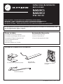
RAKUVC1
RAKUVC2
PTAC UVC Kit
Before you begin - Read these instructions completely and carefully.
IMPORTANT – OBSERVE ALL GOVERNING CODES AND ORDINANCES.
Note to Installer – Be sure to leave these instructions with the Consumer.
Note to Consumer – Keep these instructions with your Owner’s Manual for future reference.
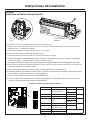
Parts Included
• Junction Box Assembly
• UVC Air Cutoff Assembly
• UVC Main Board Assembly
• UVC Wiring Harness
• Ground Wire
• Polybag with Screws
Tools Needed
• 5/16” Nut Driver
• 1/4” Nut Driver
• High Voltage discharge pliers
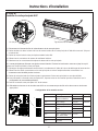
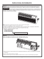
Installation Overview
GE is a trademark of the General Electric Company. Manufactured under trademark license.
Junction Box Assembly $LU&XWRႇ$VVHPEO\ Main Board Assembly
Wiring Harness

2
Installation Instructions
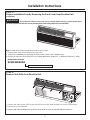
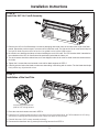
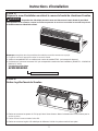
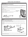
STEP 1:
Prepare Installation Area by Removing the Front Cover from Zoneline Unit
(if applicable)
WARNING
5LVNRI(OHFWULFDO6KRFNFDQFDXVHLQMXU\RUGHDWK%HIRUHVHUYLFLQJVZLWFKSRZHURႇDW
the service panel and lock the area to prevent power from being switched on accidentally.
Note: Record all Aux Mode settings before beginning this project.
1. Remove power from unit and remove the Front cover.
9HULI\89&FRPSDWDELOLW\E\FRQ¿UPLQJWKH37$&PRGHOQXPEHUVHHH[DPSOHEHORZ
&RQ¿UP\RXKDYHWKHFRUUHFW89&NLWIRU\RXUYROWDJHDSSOLFDWLRQ5$.89&95$.89&9
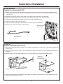
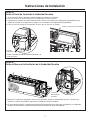
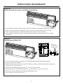
STEP 2:
Remove Vent Grille from Zoneline Unit
1. Remove and retain the four 5/16” screws securing the air louver. Note orientation of louver for replacement.
2. Remove louver and set aside.
5HPRYHDQGUHWDLQWKHZHOGHGZLUHJULGIURPWKHDLUGHÀHFWRUXVLQJDVPDOOÀDWEODGHGVFUHZGULYHU
Nomenclature Example
AZ45E09DABW5
Engineering Revision - Must be 5 or higher

3
Installation Instructions
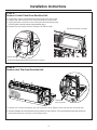
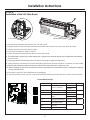
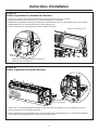
STEP 4:
Remove Vent Trim from Zoneline Unit
1. Remove the 7 screws securing the vent trim using 5/16” driver. Retain screws and vent trim to reinstall later.
2Q9PRGHOVWKHYHQWWKHUPLVWRUZLOOEHSUHVHQWRQWKH9HQWWULP7KHYHQWWKHUPLVWRUZLUHVZLOOQHHGWREH
disconnected from the connector on the wiring harness.
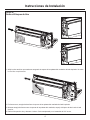
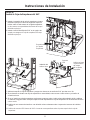
STEP 3:
Remove Control Panel from Zoneline Unit
1. If applicable, remove and discard the existing junction box and screws.
2. Remove and retain the three 5/16” screws securing the control panel.
3. Unplug the power connection to the control panel and personality plugs.
DPSSRZHUFRUGVGRQRWKDYHDSHUVRQDOLW\SOXJ
4. Remove the control panel from the Zoneline unit and set aside.
Remove and retain 3 screws
Junction Box
Remove and discard existing junction box, if present.
7KHUPLVWRU
wire connector

4
Installation Instructions
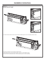
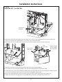
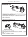
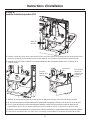
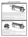
STEP 5:
5HPRYHWKH$LU&XWRႇ
1. Loosen the two screws that secure the left side fan blade support. Do not completely remove screws.
2. Gently pull outward on the left side fan blade support.
:KLOHJHQWO\SXOOLQJRQWKHIDQEODGHVXSSRUWSXOOWKHDLUFXWRႇWRZDUGWKHULJKW
5HPRYHWKHDLUFXWRႇDQGGLVFDUG,WZLOOEHUHSODFHGE\WKHQHZ89&DVVHPEO\
AIR CUTOFF

5
Installation Instructions
STEP 6:
,QVWDOOWKH89&$LU&XWRႇ$VVHPEO\
5HPRYHWKH89&$LU&XWRႇDVVHPEO\IURPWKHNLWSDFNDJLQJDQGLQVWDOOLWLQWRWKHXQLWZKHUHWKHROGDLUFXWRႇZDV
SODFHG5HSHDWWKHSUHYLRXVVWHSVLQUHYHUVHRUGHUWRLQVWDOOWKHFXWRႇ7KHULJKWHQGRIWKHDLUFXWRႇVKRXOGVOLSLQWR
the right fan blade support and the left end can be guided into the left fan blade support.
%HFDUHIXOQRWWRGDPDJHWKHLQGRRUFRLOZKHQLQVWDOOLQJWKHQHZ89&FXWRႇ7KH89&EUDFNHWZKLFKLVDWWDFKHGWR
WKHXQGHUVLGHRIWKH89&$LU&XWRႇVKRXOGEHSRVLWLRQHGMXVWEHKLQGWKHLQGRRUFRLO
7KHZLUHKDUQHVVVKRXOGEHUHWDLQHGWDXWDVLWZDVVKLSSHGXQGHUWKHDLUFXWRႇWRDYRLGLQFLGHQWDOFRQWDFWZLWKWKH
fan blade.
7LJKWHQWKHVFUHZVWKDWZHUHORRVHQHGRQWKHOHIWIDQEODGHVXSSRUWVLQ67(3
&DUHIXOO\VSLQWKHLQGRRUIDQEODGHWRPDNHVXUHWKDWQRWKLQJLVLQWHUIHULQJZLWKLWVPRWLRQ7KHIDQEODGHVKRXOGVSLQ
freely without any objectionable noises.
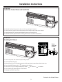
STEP 7:
Installation of the Vent Trim
3ODFHWKHYHQWWULPWKDWZDVUHPRYHGLQ67(3
2. Route the UVC wiring through the notch in the vent trim for the thermistor wires. On 265V models the UVC wiring
will share this opening with the thermistor wires. Make sure wires are not pinched.
3. Reinstall the seven 5/16” screws removed previously.
5HFRQQHFWWKHWKHUPLVWRUZLUHLISUHVHQWWRWKHZLULQJKDUQHVVIURP67(3
Use existing thermistor wire
path for UVC wiring harness

6
Installation Instructions
STEP 8:
Installation of the UVC Main Board
1. Disconnect the thermistor wire harness from the main board.
2. Remove the two screws at the top and bottom of the white main board cover using a 1/4” driver and save.
3. Remove the main board cover and set aside.
4. Disconnect the indoor fan motor connector.
5. Detach all electrical connectors from the front of the main board.
7KHPDLQERDUGLVVHFXUHGE\DZKLWHUHWDLQLQJSLQ6TXHH]HWKHFRQQHFWRUSURQJVXQWLOLWVOLGHVEDFNDQGUHOHDVHV
the main board.
7. Discharge possible stored energy from the capacitor using high voltage discharge pliers.
8. Unplug remaining connectors on the main board taking note of the connector locations. Connectors are color coded.
5HPRYHDQGGLVFDUGWKHPDLQERDUGIURPWKHFKDVVLV7KLVPDLQERDUGZLOOQRORQJHUEHXVHG
%HIRUHLQVWDOOLQJWKHQHZ89&PDLQERDUGUHIHUWRWKHPLQLPDQXDOIRULQVWUXFWLRQVRQKRZWRFRQ¿JXUHWKHVHWWLQJV
IRU\RXUVSHFL¿FPRGHO
11. Remove the new UVC main board from the kit packaging.
12. Reinstall terminals on the new UVC main board making sure black and brown wires are on their correct terminals.
1/4” screws White retaining pin
S2
S3
2341
ON CIT
2341
ON CIT
Service Board Set-Up
Switch Position Meaning Switch Setting Meaning
S2-1 OFF=heat pump
ON=air conditioner
6 Rႇ N%78
6 Rႇ
S2-2 %786HWWLQJV S2-2=on N%78
S2-3 %786HWWLQJV 6 Rႇ
S2-4 Make-up air module
¿WWHG
6 Rႇ N%78
S2-3=on
S3-1 +HDWSLSHRSWLRQ¿WWHG S2-2=on N%78
S3-2 OFF = 230/208V model
ON = 265V model
S2-3=on
S3-3 Not used
S3-4 Not used

7
Installation Instructions
STEP 8 (cont):
Installation of the UVC Main Board
7DNHWKH9UHOD\ZLUHKDUQHVVIURPWKHNLWSDFNDJLQJ7KLVZLOOKDYHDQRUDQJHFRQQHFWRUZLWKUHGDQGZKLWH
ZLUHV&RQQHFWWKHZLULQJKDUQHVVRUDQJHFRQQHFWRUWRWKHQHZPDWLQJFRQQHFWRURQWKH89&PDLQERDUG
14. Route 240V relay wire harness down the left side of the main board.
15. Align the UVC main board and engage the white retaining pin to hold the main board in place.
16. Reconnect the indoor fan motor wiring harness connector.
17. Install the main board cover.
18. Secure the main board cover using the two 1/4” screws removed earlier.
19. Reconnect the thermistor wiring harness.
Wiring Harness
New orange UVC
VSHFL¿FWHUPLQDO
STEP 9:
Install the UVC Junction Box
1. Remove the junction box assembly from the kit packaging. On models that use wall plugs, the strain relief knockout
will need to be removed.
2. Install the large white connector from the new 240V relay harness to the matching side in the junction box.
,QVWDOOWKHVPDOOWZRZLUHZKLWHFRQQHFWRUWRWKHUHFWL¿HUERDUGORFDWHGLQWKHMXQFWLRQER[DVVHPEO\
4. Dress the 240V relay harness wiring by snapping the wire tie into the mating hole on the back left corner of the
junction box.
5HFWL¿HUERDUG
Holes for wire
KDUQHVV]LSWLH

8
STEP 9:
Install the UVC Junction Box
5. Install the junction box assembly to the Main board cover. Insert the top and bottom tabs on the backside of the
junction box into the corresponding slots on the front of the main board cover.
6. Install the 5/16” Hi-Lo screw into the mating hole to secure the junction box to the main board cover.
7. Attach the junction box cover and secure with black 5/16” screw provided with kit.
8. If a junction box was previously installed in this unit, reuse the ground wire and ground screw.
9. If there was not a junction box previously installed, then remove ground wire from kit packaging and attach one end
to the hole in the front top left corner of the junction box with green ground screw.
10. Attach the other end of the screw to an existing ground location on the end bracket of the indoor coil.
11. Attach the white UVC led connector to the corresponding connector on the top of the junction box.
Installation Instructions
Junction Box
Assembly
Ground wire
attachment
LED
Connector
Attach the back
of the junction
ER[FRYHU¿UVW

9
Printed in the United States
Installation Instructions
STEP 10:
Install the Control Panel and Vent Grille
1. Reinstall the black wire mesh to the vent trim by pressing it into place.
2. Reconnect the Control Panel wiring harness and reinstall Control Panel to the chassis.
3. Install the three 5/16” screws removed earlier to secure Control Panel.
4. Reinstall the Vent grille and secure it using the four 5/16” screws removed earlier.
STEP 11:
Enabling UVC Mode
1. Reconnect power and heater wire personality jumper.
7XUQRQSRZHUWRWKHXQLW
:KHQWKHXQLWLVLQ6723PRGHSUHVVWKHUHG$X[VHWEXWWRQORFDWHGDERYHWKHMXQFWLRQER[
4. Press the MODE button until a “ ” appears on the display.
5. Press the +/- keys to change the display to either “ ” for enable or “ ” for disable.
6. Press the Aux set button again to save and exit.
5HLQVWDOOWKH37$&)URQW&RYHU
Red
Aux Set
Button

31-5000582 Rev. 0 01-21 GEA
Les trousses RAKUVC1 et RAKUVC2 sont conçues pour utilisation avec les modèles Zoneline AZ45 et AZ65
avec le chiffre technique « 5 » ou supérieur.
Instructions d’installation pour
votre nouveau
RAKUVC1
RAKUVC2
PTAC UVC Kit
Avant de commencer - Lisez ces instructions attentivement et en entier.
IMPORTANT – OBSERVEZ TOUS LES CODES ET RÈGLEMENTS EN VIGUEUR.
Note à l’installateur – Assurez-vous de laisser ces instructions au consommateur.
Note au consommateur - Conservez ces instructions avec votre manuel d’utilisation pour consultation ultérieure.
Pièces incluses
• Boîte de jonction
• Volet d’arrêt d’air UVC
• Carte principale UVC
• Faisceau de fils UVC
• Fil de terre
• Sac de vis
Outils requis
• Tournevis à douille 5/16 po
• Tournevis à douille 1/4 po
• Pince de décharge de haute tension
Aperçu de l’installation
GE est une marque de commerce de General Electric Company. Fabriqué sous licence de marque.
Boîte de jonction Volet d’arrêt d’air Carte principale
)DLVFHDXGH¿OV

2
Instructions d’installation
ÉTAPE 1:
Préparer la zone d’installation en retirant le couvercle frontal du climatiseur Zoneline
WARNING
Risque de choc électrique pouvant causer une blessure ou la mort. Avant de procéder à
XQHUpSDUDWLRQRXXQHQWUHWLHQFRXSH]OHFRXUDQWDXSDQQHDXGHVHUYLFHHWYHUURXLOOH]OD]RQHD¿QGHSUpYHQLU
le rétablissement accidentel du courant.
Remarque: enregistrez tous les paramètres du mode Aux avant de commencer ce projet.
1. Coupez le courant à l’appareil et retirez le couvercle frontal.
9pUL¿H]ODFRPSDWLELOLWp89&HQFRQ¿UPDQWOHQXPpURGHPRGqOH37$&YRLUH[HPSOHFLGHVVRXV
&RQ¿UPH]TXHYRXVDYH]ODWURXVVH89&TXLFRUUHVSRQGjODWHQVLRQGHYRWUHLQVWDOODWLRQ5$.89&9
5$.89&9
ÉTAPE 2:
Retirez la grille d’évent du Zoneline
5HWLUH]HWFRQVHUYH]OHVTXDWUHYLVSRTXL¿[HQWO¶pYHQWjODPHV1RWH]O¶RULHQWDWLRQGHO¶pYHQWjODPHVSRXUOD
remise en place.
2. Retirez l’évent à lames et mettez-le de côté.
5HWLUH]HWFRQVHUYH]ODJULOOHj¿OPpWDOOLTXHGXGpÀHFWHXUjO¶DLGHG¶XQSHWLWWRXUQHYLVjODPHSODWH
Exemple de nomenclature
AZ45E09DABW5
Révision technique - Doit être 5 ou supérieur

3
Instructions d’installation
ÉTAPE 4:
Retirer la garniture d’évent du Zoneline
5HWLUH]OHVYLVTXL¿[HQWODJDUQLWXUHG¶pYHQWjO¶DLGHG¶XQWRXUQHYLVjGRXLOOHSR&RQVHUYH]OHVYLVHWOD
garniture d’évent pour réinstallation ultérieure.
6XUOHVPRGqOHV9ODWKHUPLVWDQFHGHO¶pYHQWVHUDVLWXpHVXUODJDUQLWXUHG¶pYHQW/HV¿OVGHODWKHUPLVWDQFH
G¶pYHQWGHYURQWrWUHGpEUDQFKpVGXFRQQHFWHXUGXIDLVFHDXGH¿OV
ÉTAPE 3:
Retirez le panneau de commande du Zoneline
1. Si elle est présente, retirez et jetez proprement la boîte de jonction et les vis existantes.
5HWLUH]HWFRQVHUYH]OHVWURLVYLVSRTXL¿[HQWOHSDQQHDXGHFRPPDQGH
'pEUDQFKH]ODFRQQH[LRQpOHFWULTXHDXSDQQHDXGHFRPPDQGHDLQVLTXHOHV©SHUVRQDOLW\SOXJVªOHVFRUGRQV
G¶DOLPHQWDWLRQ$QHVRQWSDVPXQLVG¶XQH©SHUVRQDOLW\SOXJª
4. Retirez le panneau de commande du Zoneline et mettez-le de côté.
Retirer et conserver 3 vis
Boîte de
jonction
Retirer et jeter proprement la boîte de jonction
existante si elle est présente
&RQQHFWHXUGX¿O
de thermistance

4
Instructions d’installation
ÉTAPE 5:
Retirer le volet d’arrêt d’air
'HVVHUUH]OHVGHX[YLVTXLTXL¿[HQWOHVXSSRUWGHSDOHGHYHQWLODWHXUJDXFKH1HUHWLUH]SDVOHVYLVFRPSOqWHPHQW
2. Tirez avec soin le support de pale de ventilateur gauche vers l’extérieur.
3. Tout en tirant avec soin ce support, tirez le volet d’arrêt d’air vers la droite.
4. Retirer le volet d’arrêt d’air et jetez-le proprement. Il sera remplacé par le nouveau stérilisateur UVC.
AIR CUTOFF

5
Instructions d’installation
ÉTAPE 6:
Installer le volet d’arrêt d’air UVC
1. Retirez le volet d’arrêt d’air UVC de l’emballage de la trousse et installez-le sur le climatiseur, là où l’ancien volet
d’arrêt d’air était situé. Répétez les étapes précédentes dans l’ordre inverse pour installer le volet d’arrêt d’air.
L’extrémité droite du volet d’arrêt d’air doit glisser dans le support de pales de ventilateur droit, et l’extrémité gauche
peut être guidée dans le support de pales de ventilateur gauche.
2. Veillez à ne pas endommager le serpentin intérieur lorsque vous installez le nouveau volet d’arrêt d’air UVC. Le
support UVC attaché sur le dessous du volet d’arrêt d’air UVC doit être situé juste derrière le serpentin intérieur.
/HIDLVFHDXGH¿OVGRLWUHVWHUWHQGXWHOTX¶H[SpGLpHQGHVVRXVGXYROHWG¶DUUrWG¶DLUD¿QG¶pYLWHUOHFRQWDFW
accidentel avec la pale du ventilateur.
4. Serrez les 2 vis qui ont été desserrées sur le support de pale de ventilateur gauche à l’ÉTAPE 5.
(QXVDQWGHSUXGHQFHIDLWHVWRXUQHUODSDOHGHYHQWLODWHXULQWpULHXUHSRXUYpUL¿HUTXHULHQQHJrQHVRQPRXYHPHQW
La pale du ventilateur doit tourner librement sans bruit douteux.
ÉTAPE 7:
Installer la garniture d’évent
1. Remettez en place la garniture d’évent retirée à l’ÉTAPE 4.
$FKHPLQH]OHFkEODJH89&jWUDYHUVO¶HQFRFKHGHODJDUQLWXUHG¶pYHQWSRXUOHV¿OVGHWKHUPLVWDQFH6XUOHVPRGqOHV
9OHFkEODJH89&SDUWDJHFHWWHRXYHUWXUHDYHFOHV¿OVGHWKHUPLVWDQFH$VVXUH]YRXVTXHOHV¿OVQHVRQWSDV
coincés.
3. Réinstallez les sept vis 5/16 po retirées précédemment.
5HFRQQHFWH]OH¿OGHWKHUPLVWDQFHVLSUpVHQWVXUOHIDLVFHDXGH¿OVGHO¶e7$3(
8WLOLVHUOHSDUFRXUVGX¿OGHWKHUPLVWDQFH
H[LVWDQWSRXUOHIDLVFHDXGH¿OV89&

6
Instructions d’installation
ÉTAPE 8:
Installer la carte principale UVC
'pFRQQHFWH]OHIDLVFHDXGH¿OVGHODWKHUPLVWDQFHGHODFDUWHSULQFLSDOH
2. Retirez les deux vis dans le haut et le bas du couvercle blanc de la carte principale à l’aide d’un tournevis 1/4 po et
conservez-les.
3. Retirez le couvercle de la carte principale et mettez-le de côté.
4. Débranchez le connecteur du moteur du ventilateur intérieur.
5. Détachez tous les connecteurs électriques du devant de la carte principale.
/DFDUWHSULQFLSDOHHVW¿[pHSDUXQHWLJHGHUHWHQXHEODQFKH3UHVVH]OHVEURFKHVGXFRQQHFWHXUMXVTX¶jFHTX¶LO
glisse vers l’arrière et libère la carte principale.
7. Déchargez l’énergie possiblement stockée dans le condensateur à l’aide de la pince de décharge de haute tension.
8. Débranchez les autres connecteurs sur la carte principale en notant l’emplacement des connecteurs. Les
FRQQHFWHXUVVRQWLGHQWL¿pVSDUGHVFRXOHXUV
9. Retirez la carte principale du châssis et jetez-la proprement. Cette carte principale ne sera plus utilisée.
10. Avant d’installer la nouvelle carte principale UVC, reportez-vous au mini-manuel pour des instructions sur la
FRQ¿JXUDWLRQGHYRWUHPRGqOHSDUWLFXOLHU
11. Retirez la nouvelle carte principale UVC de la trousse.
5pLQVWDOOH]OHVERUQHVVXUODQRXYHOOHFDUWH89&HQYRXVDVVXUDQWTXHOHV¿OVQRLUHWEUXQVRQWVXUOHVERUQHV
appropriées.
Vis 1/4 po Tige de retenue blanche
S2
S3
2341
ON CIT
2341
ON CIT
&RQ¿JXUDWLRQGHODFDUWHGHVHUYLFH
Switch Position Meaning Switch Setting Meaning
S2-1 OFF=heat pump
21 DLUFRQGLWLRQHU
6 Rႇ 15k BTU
6 Rႇ
S2-2 BTU Settings S2-2=on 12k BTU
S2-3 BTU Settings 6 Rႇ
S2-4 Make-up air module
¿WWHG
6 Rႇ 9k BTU
S2-3=on
S3-1 +HDWSLSHRSWLRQ¿WWHG S2-2=on 7k BTU
S3-2 OFF = 230/208V model
21 9PRGHO
S2-3=on
S3-3 1RWXVHG
S3-4 1RWXVHG

7
Instructions d’installation
ÉTAPE 8 (suite):
Installer la carte principale UVC
5HWLUH]OHIDLVFHDXGH¿OVGHUHODLV9GHODWURXVVH&HIDLVFHDXHVWPXQLG¶XQFRQQHFWHXURUDQJHDYHF¿OV
URXJHHWEODQF%UDQFKH]OHFRQQHFWHXURUDQJHGXIDLVFHDXVXUOHQRXYHDXFRQQHFWHXUFRUUHVSRQGDQWGHODFDUWH
principale UVC.
$FKHPLQH]OHIDLVFHDXGH¿OVGXUHODLV9YHUVOHEDVGXF{WpJDXFKHGHODFDUWHSULQFLSDOH
$OLJQH]ODFDUWHSULQFLSDOH89&HWLQVpUH]ODWLJHGHUHWHQXHEODQFKHSRXU¿[HUODFDUWHHQSODFH
5HEUDQFKH]OHFRQQHFWHXUGXIDLVFHDXGH¿OVGXPRWHXUGHYHQWLODWHXULQWpULHXU
17. Installez le couvercle de la carte principale.
18. Fixez le couvercle de la carte à l’aide des deux vis 1/4 po retirées précédemment.
5HFRQQHFWH]OHIDLVFHDXGH¿OVGHODWKHUPLVWDQFH
)DLVFHDXGH¿OV
1RXYHOOHERUQH
UVC orange
ÉTAPE 9:
Installer la boîte de jonction UVC
1. Retirez la boîte de jonction de la trousse. Sur les modèles qui utilisent des « wall plugs », il faut retirer la débouchure
du serre-câble.
,QVWDOOH]OHJUDQGFRQQHFWHXUEODQFGXQRXYHDXIDLVFHDXGH¿OVGHUHODLV9VXUOHF{WpFRUUHVSRQGDQWGHODERvWH
de jonction.
,QVWDOOH]OHSHWLWFRQQHFWHXUEODQFjGHX[¿OVVXUODFDUWHGXUHGUHVVHXUVLWXpHGDQVODERvWHGHMRQFWLRQ
$WWDFKH]OHIDLVFHDXGH¿OVGHUHODLV9HQLQVWDOODQWXQHDWWDFKHGHFkEOHGDQVOHWURXFRUUHVSRQGDQWVXUOHFRLQ
gauche arrière de la boîte de jonction.
Carte du redresseur
Trous pour
l’attache du
IDLVFHDXGH¿OV

8
ÉTAPE 9:
Installer la boîte de jonction UVC
5. Installez la boîte de jonction sur le couvercle de la carte principale. Insérez les languettes du haut et du bas de la face
arrière de la boîte de jonction dans les fentes correspondantes sur le devant du couvercle de la carte principale.
,QVWDOOH]ODYLV+L/RSRGDQVOHWURXFRUUHVSRQGDQWSRXU¿[HUODERvWHGHMRQFWLRQVXUOHFRXYHUFOHGHOD
carte principale.
$WWDFKH]OHFRXYHUFOHGHODERvWHGHMRQFWLRQHW¿[H]jO¶DLGHGHODYLVQRLUHSRIRXUQLHGDQVODWURXVVH
6LXQHERvWHGHMRQFWLRQDpWpSUpFpGHPPHQWLQVWDOOpHGDQVFHWDSSDUHLOUpXWLOLVH]OH¿OGHWHUUHHWODYLVGHWHUUH
6¶LOQ¶\DSDVGHERvWHGHMRQFWLRQSUpFpGHPPHQWLQVWDOOpHUHWLUH]OH¿OGHWHUUHGHODWURXVVHHWDWWDFKH]XQH
extrémité dans le trou du coin gauche supérieur avant de la boîte de jonction à l’aide de la vis de terre verte.
$WWDFKH]O¶DXWUHH[WUpPLWpGX¿OjXQSRLQWGHPLVHjODWHUUHH[LVWDQWVXUOHVXSSRUWG¶H[WUpPLWpGXVHUSHQWLQLQWpULHXU
11. Branchez le connecteur DEL UVC blanc sur le connecteur correspondant sur le dessus de la boîte de jonction.
Instructions d’installation
Boîte de
jonction
Point de
¿[DWLRQGX¿O
de terre
Connecteur
DEL
Fixer d’abord
l’arrière du
couvercle de
la boîte de
jonction

9
Imprimé aux États-Unis
Instructions d’installation
ÉTAPE 10:
IInstaller le panneau de commande et la grille d’évent
1. Réinstallez le treillis métallique noir sur la garniture d’évent en le pressant en place.
5HFRQQHFWH]OHIDLVFHDXGH¿OVGXSDQQHDXGHFRPPDQGHHWUpLQVWDOOH]OHSDQQHDXGHFRPPDQGHVXUOHFKkVVLV
3. Fixez le panneau de commande en réinstallant les trois vis 5/16 po retirées plus tôt.
5pLQVWDOOH]ODJULOOHG¶pYHQWHW¿[H]ODDYHFOHVTXDWUHYLVSRUHWLUpHVSOXVW{W
ÉTAPE 11:
Activation du mode UVC
5pWDEOLVVH]O¶DOLPHQWDWLRQpOHFWULTXHHWUHEUDQFKH]OHFDYDOLHU3HUVRQDOLW\GHO¶pOpPHQWFKDXႇDQW
0HWWH]OHFOLPDWLVHXUVRXVWHQVLRQ21
/RUVTXHO¶DSSDUHLOHVWGDQVOHPRGH6723DUUrWSUHVVH]OHERXWRQ$X[6HWURXJHVLWXpDXGHVVXVGHODERvWHGH
jonction.
4. Pressez le bouton MODE jusqu’à voir apparaître “ ” sur l’écran.
3UHVVH]OHVWRXFKHVSRXUIDLUHSDVVHUO¶DႈFKDJHj³ ” pour activer ou “ ” pour désactiver.
6. Pressez le bouton Aux Set de nouveau pour sauvegarder et quitter.
7. Réinstallez le couvercle frontal du climatiseur PTAC.
Bouton
Aux Set
rouge

31-5000582 Rev. 0 01-21 GEA
Los kits RAKUVC1 y RAKUVC2 fueron diseñados para funcionar con los modelos de Zoneline AZ45 y AZ65
con una ingeniería de 5 dígitos o superior.
Instrucciones de Instalación
para su nuevo
RAKUVC1
RAKUVC2
PTAC UVC Kit
Antes de comenzar – lea estas instrucciones completamente y de forma detenida.
IMPORTANTE – CUMPLA CON TODOS LOS CÓDIGOS Y ORDENANZAS GUBERNAMENTALES.
Nota para el Instalador – Asegúrese de entregar estas instrucciones al Consumidor.
Nota para el Consumidor – Guarde estas instrucciones con su Manual del Propietario para referencia futura.
Piezas Incluidas
• Ensamble de la Caja de Empalmes
• Ensamble para el Bloqueo de Aire del UVC
• Ensamble del Tablero Principal del UVC
• Arnés de Cableado del UVC
• Cable a Tierra
• Bolsa de Polietileno con Tornillos
Herramientas Necesarias
• Llave de Tuercas de 5/16”
• Llave de Tuercas de 1/4”
• Pinzas de descarga de alto voltaje
Información General de la Instalación
GE Appliances es una marca de General Electric Company. Fabricado bajo licencia de la marca.
Ensamble de la Caja de Empalmes
Ensamble del
Bloqueo de Aire
Ensamble del Tablero
Principal
Arnés del Cableado

2
Instrucciones de Instalación
PASO 1:
Prepare el Área de Instalación Retirando la Tapa Frontal de la Unidad del Zoneline
WARNING
Existe riesgo de descargas eléctricas que pueden ocasionar lesiones o la muerte. Antes de
FRPHQ]DUFRQODUHSDUDFLyQDSDJXHHOLQWHUUXSWRUGHOSDQHOGHOVHUYLFLR\EORTXHHHOiUHDD¿QGHHYLWDUTXHOD
corriente se active de forma accidental.
Nota: Grabe todos los ajustes del modo auxiliar antes de comenzar este proyecto.
1. Desconecte la unidad de la corriente y retire la tapa frontal.
9HUL¿TXHODFRPSDWLELOLGDGFRQ89&FRQ¿UPDQGRHOQ~PHURGHPRGHORGH37$&YHUHMHPSORDFRQWLQXDFLyQ
&RQ¿UPHTXHFXHQWDFRQHONLWGH89&FRUUHFWRSDUDODDSOLFDFLyQGHOYROWDMH
5$.89&95$.89&9
PASO 2:
Retire la Rejilla de Ventilación de la Unidad del Zoneline
5HWLUH\FRQVHUYHORVFXDWURWRUQLOORVGH´DVHJXUDQGRODUHMLOODGHDLUH2EVHUYHODRULHQWDFLyQGHODUHMLOODSDUD
el reemplazo.
2. Retire la rejilla y deje la misma a un costado.
5HWLUH\FRQVHUYHODJULOODGHFDEOHVVROGDGRVGHOGHÀHFWRUGHDLUHXVDQGRXQGHVWRUQLOODGRUGHSXQWDSODQD
Ejemplo de Nomenclatura
AZ45E09DABW5
5HYLVLyQGH,QJHQLHUtD±'HEHUiVHURVXSHULRU
La page charge ...
La page charge ...
La page charge ...
La page charge ...
La page charge ...
La page charge ...
La page charge ...
La page charge ...
-
 1
1
-
 2
2
-
 3
3
-
 4
4
-
 5
5
-
 6
6
-
 7
7
-
 8
8
-
 9
9
-
 10
10
-
 11
11
-
 12
12
-
 13
13
-
 14
14
-
 15
15
-
 16
16
-
 17
17
-
 18
18
-
 19
19
-
 20
20
-
 21
21
-
 22
22
-
 23
23
-
 24
24
-
 25
25
-
 26
26
-
 27
27
-
 28
28


GE RAKUVC1 Guide d'installation
- Taper
- Guide d'installation
- Ce manuel convient également à
dans d''autres langues
- English: GE RAKUVC1 Installation guide
- español: GE RAKUVC1 Guía de instalación
Documents connexes
-
GE AZ95H12EAC Mode d'emploi
-
GE AZ91H09D5E Le manuel du propriétaire
-
GE AZ91H09E5CW1 Le manuel du propriétaire
-
GE AZ91H12D2C Mode d'emploi
-
GE Zoneline AZ91H18E3C Le manuel du propriétaire
-
-
GE AZ91H18D3C Le manuel du propriétaire
-
GE AZ45E07EAC Le manuel du propriétaire
-
-
GE Zoneline RAK204D20C Manuel utilisateur