
1
L-C2-197
REV 9 - 1004081058
Robert H. Peterson Co. • 14724 East Proctor Avenue • City of Industry, CA 91746
INSTALLER: Leave these instructions with consumer.
CONSUMER: Retain for future reference.
INSTALLATION AND OPERATING
INSTRUCTIONS
ELECTRIC
WARMING DRAWER
WARNING
When connecting this appliance to a power
supply make sure that it is the same voltage as
the unit rating. Improper connection may cause
severe damage to the components or decrease
the performance of your Fire Magic
®
electric
warming drawer. A rating plate specifying voltage,
hertz, wattage, and amps is attached to the
unit and also located on page 3. To avoid the
risk of property damage and/or personal injury,
installation work and electrical wiring must be
performed by a qualifi ed professional installer.
This appliance must be installed in accordance
with this instruction.
• EASY INSTALLATION
• TEMPERATURE RANGE UP TO 230
o
F
• MOISTURE REGULATION
• CONCEALED CONTROL
OUTSIDE DOOR MODELS: #33830-SW
#43830-SW
FLUSH DOOR MODELS: #53830-SW
SAFETY WARNINGS & CODES
PLEASE READ AND FOLLOW
• Removing permanently affi xed rating label
warnings WILL void the warranty.
• Observe all local codes and ordinances when
installing this appliance. If no local codes are
applicable, wire unit in accordance with the
National Electrical Code, ANSI/NFPA 70, latest
edition.
GENERAL INFORMATION
• When installing this unit directly below another unit,
only install with Fire Magic
®
built-in products.
• This appliance does not contain a fuse or surge
protector.
• The power to the unit must be made readily
accessible to the operator through means of a line
disconnect switch, circuit breaker, and/or easy to
reach receptacle.
• For safe operation ensure that the unit is grounded
properly per applicable electrical codes.
• Not following these instructions exactly will void
the manufacturer’s warranty.
• For outdoor installation, the circuit must have
ground fault interrupt.
FEATURES:
WARNING
To minimize the risk of property damage and/or
personal injury, do not use a fl exible extension
power-supply cord in addition to the one supplied
with this appliance.
Important: Read these instructions carefully
before starting installation.
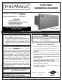
33830-SW shown
254-B-07B-5
Certifi ed to: ANSI Z21.58-2007
CSA 1.6-2007

2
L-C2-197
REV 9 - 1004081058
Robert H. Peterson Co. • 14724 East Proctor Avenue • City of Industry, CA 91746
INSTALLATEUR: Laissez ces instructions avec le
consommateur. CONSOMMATEUR: Maintenez pour la
future référence.
INSTALLATION ET CONSIGNES
D’UTILISATION
ÉLECTRIQUE TIROIR
DE CHAUFFAGE
AVERTISSEMENT
En reliant cet appareil à une alimentation
d’énergie assurez-vous que c’est la même
tension que l’estimation d’unité. Le raccordement
inexact peut endommager considérablement les
composants ou diminuer l’exécution de votre
tiroir de chauffage électrique de Magic® du feu.
Une plaque de contrôle indiquant la tension, les
hertz, la puissance en watts, et les ampères
est attachée à l’unité et également située à la
page 4. Pour éviter le risque de dégats matériels
et/ou de blessures, le travail d’installation et le
câblage électrique doivent être exécutés par un
installateur professionnel qualifi é. Cet appareil
doit être installé selon cette instruction.
• INSTALLATION FACILE
• TEMPÉRATURE AMBIANTE JUSQU’À 230
o
F
• RÈGLEMENT D’HUMIDITÉ
• COMMANDE CACHÉE
AVERTISSEMENTS ET CODES DE SÛRETÉ
SVP LISEZ ET SUIVEZ
• Enlever des avertissements de manière per-
manente apposés d’étiquette d’estimation
videra la garantie.
• Observez tous les codes et ordonnances lo-
caux en installant cet appareil. Si aucun code
local n’est applicable, l’unité de fi l selon le code
électrique national, ANSI/NFPA 70, la dernière
édition.
INFORMATIONS GÉNÉRALES
• En installant cette unité directement au-dessous
d’une autre unité, installez seulement avec des
produits de fonction intégrée de Magic® du feu.
• Cet appareil ne contient pas un fusible ou un
protecteur de montée subite.
• La puissance à l’unité doit être rendue aisément
accessible à l’opérateur par des moyens d’une
ligne commutateur de débranchement, disjoncteur,
et/ou facile d’atteindre le réceptacle.
• Pour l’exploitation sûre assurez-vous que l’unité
est fondue correctement par codes électriques
applicables.
• Non suivant ces instructions exactement videront
la garantie du fabricant.
• Pour l’installation extérieure, le circuit doit avoir
rectifi é l’interruption de défaut.
DISPOSITIFS:
AVERTISSEMENT
Pour réduire au minimum le risque de dégats
matériels et/ou de blessures, n’employez pas une
prolongation fl exible puissance-fournissent la corde
en plus de celle fournie avec cet appareil.
Important: Lisez ces instructions soigneusement
avant de commencer l’installation.
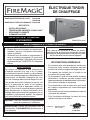
33830-SW montré
MODÈLES EXTÉRIEURS DE PORTE: #33830-SW
#43830-SW
MODÈLES DE PORTE AFFLEURANTE: #53830-SW
254-B-07B-5
Certifi ed to: ANSI Z21.58-2007
CSA 1.6-2007

3
L-C2-197
REV 9 - 1004081058
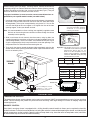
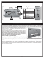
Fig. 3-2
Grounded
receptacle
Grounded plug
Ground pin
WARNING: Be sure to unplug unit before
servicing and allow heating
elements to cool before
removing the drawer.
Before installing your Fire Magic
®
warming drawer, remove the drawer by
completely pulling it out. Release the drawer from the drawer slides by pressing
the black lever down on the right side, and up on the left side
(Fig 3-1). Then pull
outward on the drawer until it comes free of the runners.
For proper installation, be sure to use the correct cutout dimensions as
specifi ed for your specifi c model number (see table below).
1. In order to properly support the weight of your warming drawer, it is necessary
to provide a secure, level surface in the rear of the unit. (See SIDE VIEW
drawing below.) This may be accomplished by using bricks, 2 X 4’s, etc. Be
sure that the height of this rear support is
1
/
8
" higher than that of the front
opening support, so that your drawer sits level.
Note: It is recommended that silicon caulking (not supplied) is applied around
the back of the warming drawer cabinet trim before sliding the cabinet
assembly into the opening.
2. Slide in and fasten the unit securely into the masonry using lag bolts (not
supplied) through the installation screw slots in the top and bottom of the unit
(see drawings below). Once all four bolts are fastened securely, be sure to
snap the supplied plugs fi rmly into place over the screw slot openings. This
will prevent heat loss and moisture from entering the unit.
3. To re-attach the drawer; extend the drawer slides completely and align the
drawer into the slides, pushing the drawer closed. Open the drawer to verify
that it has locked in place.
TEMPERATURE CONTROL
The temperature of your warming drawer can be set to a maximum of 230°F to accommodate any and all of your warming
needs. The low settings are perfect for plate and bread warming, while high settings are useful in keeping soups and
sauces piping hot.
HUMIDITY CONTROL
Your electric warming drawer is equipped with a sliding humidity control knob that allows you to regulate the humidity
inside the drawer. To make it more convenient, adjusting the moisture is done without opening the drawer and affecting the
interior temperature and/or humidity. Open the vents to keep foods crisp; close the vents to keep foods moist (add water
to the moisture cup to increase the interior humidity).
INSTALLATION
INSTALLATION
Important: This product is for use on a standard
120-volt AC circuit and has a grounded
plug like the plug in Fig. 3-2. If it
does not fit the receptacle, have a
proper outlet installed by a qualifi ed
electrician. DO NOT modify the plug
provided with this product.
VOLTS WATTS AMPS HZ
120 475 3.96 60
Important: Must be used with a GFI equipped
outlet or circuit.
OPERATION
OPERATION
Drawer
support
Side view
Prior to installing bolt, use the
screwdriver to clear a small
path through the insulation.
Insulation
Drawer front
Y
Z
X
33830-SW
shown
CUTOUT DIMENSION
Model # X Y Z
33830-SW 31" 13" 20 1/2"
43830-SW 31" 13" 20 1/2"
53830-SW 32 1/4" 14 1/2" 22"
Fig. 3-1

4
L-C2-197
REV 9 - 1004081058
Le schéma 4-2
Réceptacle fondé
Prise fondée
Goupille moulue
AVERTISSEMENT: Soyez sûr de
débrancher l’unité avant l’entretien et de
permettre à des éléments de chauffe de
se refroidir avant d’enlever le tiroir.
LA COMMANDE DE TEMPÉRATURE
La température de votre tiroir de chauffage peut être placée à un maximum de 230°F pour satisfaire n’importe lequel
et tous vos besoins de chauffage. Les bas arrangements sont parfaits pour le plat et le pain chauffant, alors que les
arrangements élevés sont utiles en conservant des potages et des sauces très chauds.
LA COMMANDE D’HUMIDITÉ
Votre tiroir de chauffage électrique est équipée d’un bouton de commande coulissant d’humidité qui vous permet de régler
l’humidité à l’intérieur du tiroir. La rendre plus commode, ajustant l’humidité est faite sans ouvrir le tiroir et affecter la température
et/ou l’humidité intérieures. Ouvrez les passages pour conserver des nourritures croquantes ; fermez les passages pour
conserver des nourritures moites (ajoutez l’eau à la tasse d’humidité pour augmenter l’humidité intérieure).
INSTALLATION
INSTALLATION
Important: Ce produit sert sur un circuit standard
à C.A. 120-volt et a une prise fondée
comme la prise dans le schéma 4-2.
S’il n’adapte pas le réceptacle, faites
installer une sortie appropriée par un
électricien qualifi é. Ne modifi ez pas la
prise équipée de ce produit.
VOLTS WATTS AMPÈRES HERTZ
120 475 3.96 60
Important: Doit être employé avec une sortie ou
un circuit équipée par GFI.
OPÉRATION
OPÉRATION
Appui de
tiroir
Vue de côté
Avant d’installer le boulon,
utilisez le tournevis à l’espace
libre un petit chemin par
l’isolation.
Isolation
Avant de tiroir
33830-SW
montré
DIMENSION DE COUPE-CIRCUIT
Modele # X Y Z
33830-SW 31" 13" 20 1/2"
43830-SW 31" 13" 20 1/2"
53830-SW 32 1/4" 14 1/2" 22"
Y
Z
X
Avant d'installer votre tiroir de chauffage de Magic
®
du feu, enlevez le tiroir en le
tirant complètement. Libérez le tiroir des glissières de tiroir en pressant le levier
noir vers le bas du côté droit, et levez de l'aile gauche (voir le schéma 4-1). Tirez
alors à l'extérieur sur le tiroir jusqu'à ce qu'il vienne exempt des coureurs.
Pour l'installation appropriée, soyez sûr d'employer les dimensions correctes
de coupe-circuit comme spécifi que pour votre numéro de type spécifi que
(voir le tableau ci-dessous).
1. Afi n de soutenir correctement le poids de votre tiroir de chauffage, il est nécessaire
de fournir une surface bloquée et de niveau à l'arrière de l'unité. (Voir le dessin de
VUE DE CÔTÉ ci-dessous.) Ceci peut être accompli en employant des briques,
2 x 4, etc. soit sûr que la taille de cet appui arrière est 1/8"; plus haut que cela
de l'appui avant d'ouverture, de sorte que votre tiroir se repose de niveau.
Note: On lui recommande que le calfeutrage de silicium (non fourni) soit appliqué
autour du dos de l'équilibre de chauffage de coffret de tiroir avant de glisser
le coffret dans l'ouverture.
2. Glissez dedans et attachez l'unité solidement dans la maçonnerie utilisant
des boulons de retard (non fournis) par les fentes de vis d'installation dans le
dessus et le bas de l'unité (voir les dessins ci-dessous). Une fois que chacun
des quatre boulons est attaché solidement, soyez sûr de casser les prises
fournies fermement dans l'endroit au-dessus des ouvertures de fente de vis.
Ceci empêchera la perte et l'humidité de chaleur d'écrire l'unité.
3. Pour rattacher le tiroir ; prolongez les glissières de tiroir complètement et alignez
le tiroir dans les glissières, poussant le tiroir fermé. Ouvrez le tiroir pour vérifi er
qu'il a fermé à clef en place.
Fig. 4-1

5
L-C2-197
REV 9 - 1004081058
The following care instructions will keep your unit looking and working like new. Meticulous attention has been given
to maintain the attractive fi nish throughout the manufacturing process. Like the stainless steel used in commercial
kitchens, your warming drawer requires regular cleaning and occasional
buffi ng to maintain its bright, clean appearance (the inner drawer is
removable for easy cleaning).
Clean your drawer by fi rst using Fire Magic Barbecue and Grill
Cleaner (part #3580-1) to remove grease and dirt. Always wipe with
the grain (See Fig. 5-2). Next, use Fire Magic Stainless Steel Cleaner
(3581-1) to restore the stainless steel color. Finish by wiping your
drawer down using Fire Magic Polish Wipes (3586-1).
Clean your drawer at least once a month.
If your drawer is installed in a seaside (salt air) or poolside (chlorine)
location, it will be more susceptible to corrosion and must be
maintained/cleaned more frequently. Do not store chemicals (such as chlorine or fertilizer) near your stainless steel
drawer.
Due to the nature of stainless steel, surface iron oxide deposits may appear. Do not be alarmed – these deposits
are removable with stainless-steel cleaner through prompt and periodic maintenance. If not attended to promptly,
permanent pitting may occur.
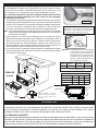
Fig. 5-1
Item
No.
Description
1 Warming drawer (1)
2 Cup (1)
3 Removable moisture
plates (4)
4 Indicator light
5 Temperature control
5
4
1
2
3
4
5
CLEANING AND MAINTENANCE
CLEANING AND MAINTENANCE
Screw slots
Wipe with the grain
Fig. 5-2
Humidity
control
Moisture cup
On/Off
indicator light
Temperature
control
OPERATION (cont.)
OPERATION (cont.)

4
PLEASE KEEP A COPY OF YOUR SALES SLIP FOR PROOF OF PURCHASE
This warranty applies to the original purchaser and to single family residential use only. It commences from date of purchase, and is valid only with
proof of purchase.
This warranty does not cover parts becoming defective through misuse, accidental damage, electrical damage, improper handling, storage, and/or
installation. Product must be installed (and gas must be connected) as specifi ed in the instructions or operator’s manual, by a qualifi ed professional
installer. Accessories, parts, valves, remotes, etc., when used must be Peterson Co. product.
This warranty does not apply to rust, corrosion, oxidation, or discoloration, unless the affected component becomes inoperable. It does not cover
labor or labor-related charges.
This warranty specifi cally excludes liability for indirect, incidental, or consequential damages. Some states do not allow the exclusion or limitation of
incidental or consequential damages, so the above exclusion may not apply to you. This warranty gives you specifi ed legal rights, and you may have
other rights that may vary from state to state.
For additional information regarding this warranty, or to place a warranty claim, contact the R.H. Peterson dealer where the product was purchased.
TO REGISTER YOUR PRODUCT ONLINE GO TO: WWW.RHPETERSON.COM,
AND CLICK ON PRODUCT REGISTRATION. THANK YOU FOR YOUR PURCHASE.
LIFETIME WARRANTY - Fire Magic
®
cast stainless-steel burners, stainless-steel rod cooking grids, and stainless-steel housings are
warranted for as long as you own your Fire Magic
®
grill.
FIFTEEN-YEAR WARRANTY - Fire Magic
®
cast brass burners, brass valves, backburner assemblies (except ignition parts), and
manifold assemblies are warranted for 15 years from the date of purchase of your Fire Magic
®
grill.
THREE-YEAR WARRANTY - Fire Magic
®
sideburners and all other Fire Magic
®
grill components (except ignition and electronic
parts) are warranted for three (3) years from the date of purchase of your Fire Magic
®
grill.
Fire Magic
®
ignition systems (excluding batteries), electronic components (including lights and thermometers), and accessories are
warranted for one (1) year from date of purchase.
Robert H. Peterson Co. • 14724 East Proctor Avenue • City of Industry, CA 91746Robert H. Peterson Co. • 14724 East Proctor Avenue • City of Industry, CA 91746
WARRANTY
-
 1
1
-
 2
2
-
 3
3
-
 4
4
-
 5
5
-
 6
6


