
WORKBENCH
0950 (F0150950 . . )
SKIL Europe BV - Konijnenberg 60 03/08 2610398631
4825 BD Breda - The Netherlands
www.skileurope.com
ME77
ORIGINAL INSTRUCTIONS . . . . . . . . . . . . . 9
NOTICE ORIGINALE . . . . . . . . . . . . . . . . . . 9
ORIGINALBETRIEBSANLEITUNG . . . . . .
10
ORIGINELE GEBRUIKSAANWIJZING. . . . 11
BRUKSANVISNING I ORIGINAL . . . . . . . . 12
ORIGINAL BRUGSANVISNING . . . . . . . . . 13
ORIGINAL DRIFTSINSTRUKS. . . . . . . . . .
14
ALKUPERÄISET OHJEET . . . . . . . . . . . . . 14
MANUAL ORIGINAL . . . . . . . . . . . . . . . . . 15
MANUAL ORIGINAL. . . . . . . . . . . . . . . . . . 16
ISTRUZIONI ORIGINALI . . . . . . . . . . . . . . 17
EREDETI HASZNÁLATI UTASÍTÁS. . . . . . 18
PÒVODNÍM NÁVODEM K POUÎÍVÁNÍ . . . 19
OR‹J‹NAL ‹fiLETME TAL‹MATI . . . . . . . . . 20
INSTRUKCJÑ ORYGINALNÑ. . . . . . . . . . . 20
ОДЛИННИК РУКОВОДСТВА
ПО ЭКСПЛУАТАЦИИ . . . . . . . . . . . . . . . .
21
ОРИГІНАЛЬНА ІНСТРУКЦІЯ
З ЕКСПЛУАТАЦІЇ . . . . . . . . . . . . . . . . . . .
22
ΠΡΩΤΤΥΠ ∆ΗΓΙΩΝ ΡΗΣΗΣ . . . . . . 23
INSTRUCØIUNI DE FOLOSIRE
ORIGINALE . . . . . . . . . . . . . . . . . . . . . . . .
24
ОРИГИНАЛНО РЪКОВОДСТВО
ЗА ЕКСПЛОАТАЦИЯ . . . . . . . . . . . . . . . .
25
PÔVODN¯ NÁVOD NA POUÎITIE. . . . . . . 26
ORIGINALNE UPUTE ZA RAD . . . . . . . . . 27
ORIGINALNO UPUTSTVO ZA RAD. . . . . . 28
IZVIRNA NAVODILA. . . . . . . . . . . . . . . . . . 28
ALGUPÄRANE KASUTUSJUHEND. . . . . . 29
INSTRUKCIJÅM ORI˛INÅLVALODÅ. . . . . 30
ORIGINALI INSTRUKCIJA . . . . . . . . . . . . . 31
GB
F
D
NL
S
DK
N
FIN
E
P
I
H
CZ
TR
PL
RU
UA
GR
RO
BG
SK
HR
SRB
SLO
EST
LV
LT

2
1
a
b
c
d
e
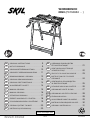
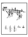
a 800 mm
b 660 mm
c 400 mm
d 160 mm
e 610 mm
2
A
BC
D
E
F
G
3

3
4 5
76a 6b

4
30º
8x
8x
12x
6x43
mm
6x12
mm
M6
2x
2x
4x
4x
4x
4x
4x
6x38
mm
6x12
mm
M6
8x45
mm
8x15
mm
M8
8a

5
2x
2x
2x
8x19,5
mm
M8
2x
2x
6x
2x
M8
8x19,5
mm
8x25
mm
4x4x
4x
4x
4x
4x
8x65
mm
8x19,5
mm
M8
8b

6
4x!
1-6
x
1-6
x
9

7
4x
0
180º
!

8
@
#

9
GB
Workbench 0950
INTRODUCTION
• The Slide and Lock system works in an entirely different
way from all other conventional clamping systems
• Read this instruction manual carefully before use and
save it for future reference 1
• Only use the parts and accessories supplied; damage
due to the use of non-original parts and accessories will
be excluded from the warranty
• This workbench is not intended to be used for
clamping electrical power tools
TECHNICAL SPECIFICATIONS 2
WORKBENCH PARTS 3
A Clamping handle
B Adjustable clamping jaw
C Support arm (max. 5 kg)
D In-between clamping block
E Fixed clamping jaw
F Worktop clamping block
G Unlocking lever
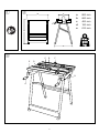
SAFETY
• Ensure that the workbench stands on a fi rm and non-
slippery surface
• Do not place heavy objects on the edge to prevent the
workbench from turning over 4
• Do not attempt to climb onto or stand on the
workbench 5
• Never load the worktop with more than 200 kg 6
• Place heavy objects calmly on the workbench; do not
drop them 7
• Keep children away from work area
• Store the workbench indoors in a dry and locked-up
place, out of reach of children
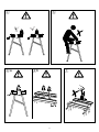
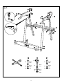
USE
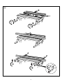
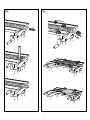
• Assembly instructions 8
- the sequence of the numbers appearing in the
drawing corresponds with the sequence of the steps
to be followed for assembling the workbench
! firmly tighten all screws and nuts
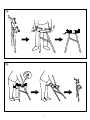
• Operating instructions 9
1
turn both clamping handles A counter-clockwise as
far as they will go (between 1 to 6 turns)
2
push adjustable clamping jaw B back as far as it will
go
3
fold out both support arms C for optimal workpiece
support
4
hold the workpiece with one hand between the jaws
(ensure that the 4 in-between clamping blocks D
are correctly aligned to the workpiece)
5
pull adjustable clamping jaw B with the other hand
towards the workpiece and fi xed clamping jaw E
6
carefully tighten each clamping handle with less than
one turn (mostly less than half a turn)
- for releasing the workpiece simply turn each
clamping handle back into the downward position
! never try to fine-adjust the clamping jaws by
turning the clamping handles counter-clockwise,
because this always results in releasing the
clamping jaws
- repeat steps 1 through 6 for every new clamping
procedure
• In-between clamping blocks 0
- always use the in-between clamping blocks to
prevent the aluminium from damage
! ensure that the workpiece is securely clamped
• Worktop clamping blocks !
! ensure that the workpiece is securely clamped
• Folding out the workbench @
• Collapsing the workbench #
- push lever G downward for unlocking the workbench
SERVICE
• If the workbench should fail despite the care taken in
manufacturing and testing procedures, repair should be
carried out by an after-sales service centre for SKIL
power tools
- send the workbench undismantled together with
proof of purchase to your dealer or the nearest SKIL
service station (addresses as well as the service
diagram are listed on www.skileurope.com)
F
Etabli 0950
INTRODUCTION
• Le système de glissière et de verrouillage fonctionne
tout à fait différemment des autres systèmes de serrage
conventionnels
• Lisez attentivement ce manuel d’instruction avant
d’utiliser l’appareil et conservez-le pour pouvoir vous y
référer ultérieurement 1
• Utilisez uniquement les pièces et accessoires fournis;
les dommages résultant de l’utilisation de pièces et
accessoires n’étant pas d’origine seront exclus de la
garantie
• Cet établi n’a pas été conçu pour être utilisé pour le
serrage d’outils électriques
SPECIFICATIONS TECHNIQUES 2

10
PIECES DE L’ETABLI 3
A Poignée de serrage
B Griffe de serrage réglable
C Bras support (max. 5 kg)
D Bloc de serrage intermédiaire
E Griffe de serrage fi xe
F Bloc de serrage du plan de travail
G Levier de déblocage
SECURITE
• Assurez-vous que l’établi se trouve sur une surface
ferme et non glissante
• Ne placez pas d’objets lourds sur le bord pour éviter
que l’établi ne se renverse 4
• Ne tentez pas de grimper ou de vous tenir debout sur
l’établi 5
• Ne chargez jamais l’établi avec plus de 200 kg 6
• Déposez les objets lourds doucement sur l’établi; ne les
laissez pas tomber 7
• Ne pas laissez les enfants s’approcher de l’aire de
travail
• Rangez l’établi à l’intérieur dans un endroit sec et
fermer à clé, hors de la portée des enfants
UTILISATION
• Instructions de montage 8
- la séquence des numéros apparaissant sur le
schéma correspond à la séquence des étapes à
suivre pour le montage de l’établi
! serrez fermement toutes les vis et les écrous
• Instructions d’utilisation 9
1
faites tourner les deux poignées de serrage A dans
le sens inverse des aiguilles d’une montre en leur
position la plus éloignée (entre 1 et 6 tours)
2
poussez la griffe de serrage réglable B en arrière
jusqu’au maximum
3
dépliez les deux bras supports C pour un soutien
optimal de la pièce à travailler
4
maintenez la pièce à travailler avec une main entre
les griffes (assurez-vous que les 4 blocs de
serrage intermédiaires D sont bien alignées avec
la pièce à travailler)
5
tirez la griffe de serrage réglable B avec l’autre main
vers la pièce à travailler et la griffe de serrage fi xe E
6
serrez soigneusement chaque poignée de serrage en
effectuant moins d’un tour (généralement moins
d’un demi-tour)
- pour libérer la pièce à travailler, faites simplement
tourner chaque poignée de serrage en position vers
le bas
! n’essayez jamais d’ajuster les griffes de serrage
avec précision en tournant les poignées de
serrage dans le sens inverse des aiguilles d’une
montre, car cette opération entraîne toujours la
libération des griffes de serrage
- répétez les étapes 1 à 6 pour chaque nouvelle
procédure de serrage
• Blocs de serrage intermédiaires 0
- utilisez toujours les blocs de serrage intermédiaires
pour éviter que l’aluminium ne soit endommagé
! assurez-vous que la pièce à travailler est
soigneusement serrée
• Blocs de serrage du plan de travail !
! assurez-vous que la pièce à travailler est
soigneusement serrée
• Dépliage de l’établi @
• Pliage de l’établi #
- poussez le levier G vers le bas pour déverrouiller
l’établi
SERVICE APRES-VENTE
• Si, malgré tous les soins apportés à la fabrication et au
contrôle de l’établi, celui ci devait avoir un défaut, la
réparation ne doit être confi ée qu’à une station de
service après-vente agréée pour outillage SKIL
- retournez l’établi non démonté avec votre preuve
d’achat au revendeur ou au centre de service après-
vente SKIL le plus proche (les adresses ainsi que la
vue éclatée fi gurent sur www.skileurope.com)
D
Werkbank 0950
EINLEITUNG
• Das Slide-and-Lock-System funktioniert völlig anders
als alle anderen konventionellen Spannsysteme
• Bitte diese Bedienungsanleitung sorgfältig durchlesen
und aufbewahren 1
• Verwenden Sie nur die mitgelieferten Teile und
Zubehörteile; Schäden aufgrund der Verwendung von
Nicht-Originalteilen und -Zubehörteilen sind von der
Garantie ausgeschlossen
• Diese Werkbank ist nicht für das Einspannen von
Elektrowerkzeugen gedacht
TECHNISCHE DATEN 2
TEILE DER WERKBANK 3
A Spanngriff
B Einstellbare Spannbacke
C Trägerarm (max. 5 kg)
D Zwischen-Spannblock
E Feste Spannbacke
F Arbeitsfl ächen-Spannblock
G Entriegelungshebel
SICHERHEIT
• Stellen Sie sicher, dass die Werkbank auf einer festen
und rutschsicheren Fläche steht
• Stellen Sie keine schweren Gegenstände auf den Rand,
um zu verhindern, dass die Werkbank umkippt 4

-
 1
1
-
 2
2
-
 3
3
-
 4
4
-
 5
5
-
 6
6
-
 7
7
-
 8
8
-
 9
9
-
 10
10
-
 11
11


