Eaton CWPD Series Wiring And Installation Manual
- Taper
- Wiring And Installation Manual

CWPD Ceiling Mounted Wireless Sensor
Wiring and Installation Manual
Overview
The Wireless Sensor is a key component of the WaveLinx
Wireless Connected Lighting System. This device provides
occupancy information of an area to the Eaton Wireless
Controller. The Wireless Sensor utilizes passive infrared
technology to determine occupancy and a photocell to provide
open loop daylighting. It is powered by standard batteries
(2 x AA) and communicates wirelessly to the Eaton Wireless
Area Controller (WAC). The Wireless Sensor is intended to
be installed onto a ceiling surface or electrical box
CWPD-1500 Extended Range
Important Safeguards
When using electrical equipment, basic safety precautions should always be followed including the following:
• READ AND FOLLOW ALL SAFETY INSTRUCTIONS.
• Do not mount near gas or electric heaters.
• Equipment should be mounted in locations and at heights where it will not readily be subjected to tampering by
unauthorized personnel.
• The use of accessory equipment is not recommended by Eaton as it may cause an unsafe condition.
• Do not use this equipment for other than the intended use.
SAVE THESE INSTRUCTIONS
Battery Installation
Two AA alkaline batteries are provided with the Wireless Sensor. When replacing these batteries, use only alkaline
type batteries. Install the batteries according to the battery compartment markings.
Warranties and Limitation of Liability
Please refer to www.eaton.com/LightingWarrantyTerms for our terms and conditions.
Garanties et limitation de responsabilité
Veuillez consulter le site www.eaton.com/LightingWarrantyTerms pour obtenir les
conditions générales.
Garantías y Limitación de Responsabilidad
Visite www.eaton.com/LightingWarrantyTerms para conocer nuestros términos y
condiciones.
Battery slot
Battery slot
Eaton
1121 Highway 74 South
Peachtree City, GA 30269
P: 770-486-4800
www.eaton.com/lighting
Canada Sales
5925 McLaughlin Road
Mississauga, Ontario L5R 1B8
P: 905-501-3000
F: 905-501-3172
© 2018 Eaton
All Rights Reserved
Printed in USA
Imprimé aux États-Unis
Impreso en los EE. UU.
Publication No. IL503036EN
July 2018
Eaton is a registered trademark.
All trademarks are property
of their respective owners.
Eaton est une marque de commerce
déposée. Toutes les autres marques
de commerce sont la propriété de
leur propriétaire respectif.
Eaton es una marca comercial
registrada. Todas las marcas
comerciales son propiedad de sus
respectivos propietarios.
Product availability, specifications,
and compliances are subject to
change without notice.
La disponibilité du produit, les
spécifications et les conformités
peuvent être modifiées sans préavis.
La disponibilidad de productos, las
especificaciones y los cumplimientos
están sujetos a cambio sin previo
aviso.

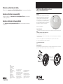
Sensor Installation
There are various methods that may be used to affix the Wireless Sensor to a ceiling surface.
Magnetic:
Magnets have been incorporated
into the Wireless Sensor allowing
the device to be affixed to a
metallic ceiling surface (metal
plate, drop-ceiling T-bar, etc).
Surface-mount:
The Wireless Sensor may be
installed directly to a ceiling surface (ceiling tile, drywall ceiling, etc). There are several techniques available to affix the Wireless
Sensor directly to ceiling surfaces.
Installation Notes
Consult www.eaton.com/lighting for the most up-to-date revision of the wireless system design guide and install this product
according to the guidelines described.
The Wireless Sensor is to be installed in dry, indoor locations ONLY. Do not install the Wireless Sensor in damp locations. Damp
locations are defined as: interior locations subject to moderate degrees of moisture, such as some basements, some barns, some
cold-storage warehouses, and the like, and partially protected locations under canopies, marquees, roofed open porches, and the like.
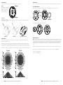
The Wireless Sensor provides 360° coverage pattern. It is recommended to install the sensor more than 4ft (1.2m) away from air supply vents.
Troubleshooting
There are no user-serviceable parts inside of the Sensor Interface Module. Please return the device to Eaton if service is required.
Sensor Mask Installation
Remove the ring (lens surround) from the sensor assembly. This can be achieved by rotating the ring counter clockwise.
Place the supplied mask and rotate clockwise until it latches.
Regulatory Approvals
Note: This equipment has been tested and found to comply with the limits for a Class A digital device, pursuant to part 15 of the FCC
Rules. These limits are designed to provide reasonable protection against harmful interference when the equipment is operated in a
commercial environment. This equipment generates, uses, and can radiate radio frequency energy and, if not installed and used in
accordance with the instruction manual, may cause harmful interference to radio communications. Operation of this equipment in a
residential area is likely to cause harmful interference in which case the user will be required to correct the interference at his own
expense.
Modifications not expressly approved by the manufacturer could void the user’s authority to operate the equipment under FCC rules.
This equipment has been tested and found to comply with Industry Canada ICES-003 Issue 5 (CAN ICES-3 (A)/NMB-3(A)).
Contains FCC ID: H79DFZM-E7220
Contains IC ID: 4259B-DFZM7220
Helical Screw Thumb Screw Drywall or Wood Screw (#6)
32
EATON WaveLinx Wireless Room Sensor Installation instructions EATON WaveLinx Wireless Room Sensor Installation instructions
Magnet
Magnet
Lens
surround
Lens
surround
Top view
Extended range
Side view
20
10
0
20
10
Feet
8
20 15 11 9 5.6 3 0 3 5.6 9 11 15 20
Feet
12
5
5
12
8
12
9
9
12
7
7
5
5
3
3
0
0
Top view
Standard range
Side view
12
5
0
12
5
Feet
8
12 9 7 5 3 0 3 5 7 9 12
Feet
-
 1
1
-
 2
2


Eaton CWPD Series Wiring And Installation Manual
- Taper
- Wiring And Installation Manual
dans d''autres langues
- English: Eaton CWPD Series
Documents connexes
Autres documents
-
Cooper Lighting WSL Linear with Wavestream LED technology Guide d'installation
-
Cooper Lighting Loft WaveStream LED Guide d'installation
-
-
-
Cooper Lighting SCMA0401 Manuel utilisateur
-
-
Cooper Lighting WIM-WH-SKIT Manuel utilisateur
-
-
Cooper Lighting WWBZIG WaveLinx Wireless Wallstation Battery Powered Guide d'installation